Hello friends, I hope you all are doing great. Today, I am going to share the new NEMA 17 Linear Stage Library for Proteus Simulation, the 45th library of our motor series. If you have searched for a Proteus simulation of a lead-screw linear stage, the part that moves the head of a 3D printer, a laser engraver or a small CNC machine, this library gives you a complete one: a NEMA 17 stepper, a T8 lead screw, a carriage on two rods and an end switch at each side, all moving in your simulation.
NEMA 17 Linear Stage Library for Proteus Simulation
Latest version: V1.0 (November 2026, this tutorial)
Other motors: SG90 Servo · TT Gear Motor · 28BYJ-48 Stepper · NEMA 17 Stepper · MG996R Servo · N20 Encoder Motor · JGA25-370 Encoder Motor · FS90R 360 Servo · 130 DC Motor · A2212 Brushless · X27.168 Gauge · Analog Panel Meter · DC Tachogenerator · LM393 Speed Sensor · MG90S Servo · DS3218 Servo · L12 Linear Servo · JGB37-520 Motor · RS-775 Motor · JGY-370 Worm Motor · 12V Linear Actuator · Coin Vibration Motor · Mini Submersible Water Pump · 12V Peristaltic Pump · 4-Pin PC Fan · 12V Push-Pull Solenoid · NEMA 23 Stepper Motor · Micro Linear Stepper · TYJ50 Synchronous Motor · Quartz Clock Movement · Air-Core Gauge · Electromechanical Counter · Split-Flap Display · Electric Bell · Wind Turbine · 8520 Coreless Motor · Car Wiper Motor · Car Door Lock Actuator · 12V Solenoid Water Valve · 12V Holding Electromagnet · Mini Air Pump · Planetary Gear Motor · 540 RC Motor · LRA Vibration Motor · 42BLF Hall BLDC Motor · 2204 Gimbal Motor · 120mm 230V AC Fan · NEMA 17 Closed-Loop Stepper · Pan-Tilt Bracket · 4-DOF Robot Arm
Motor drivers: L298 · L9110S · TB6612FNG · BTS7960 · A4988 / DRV8825 · 28BYJ-48 + ULN2003 · PCA9685 Servo · Relay Module · 30A Brushless ESC · TB6600 Stepper Driver · 60A Brushed ESC · DRV2605L Haptic Driver · ZS-X11H BLDC Driver · SimpleFOC Mini Driver · AC Dimmer Module · TMC2209 Stepper Driver · DRV8833 Motor Driver · L293D Motor Shield
Helping Tools
- Serial Monitor Advance: a serial terminal window for the UART of your board
- Serial Monitor Expert: the serial monitor with extra debugging tools
- LCD Library for Proteus V3.0: 16x2, 20x4 and I2C LCDs to show your readings
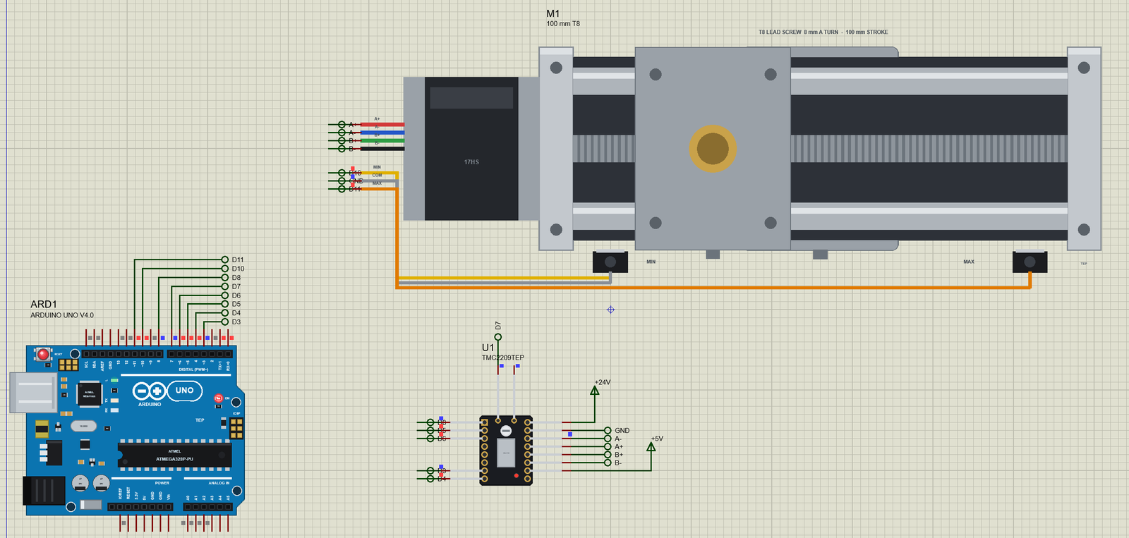
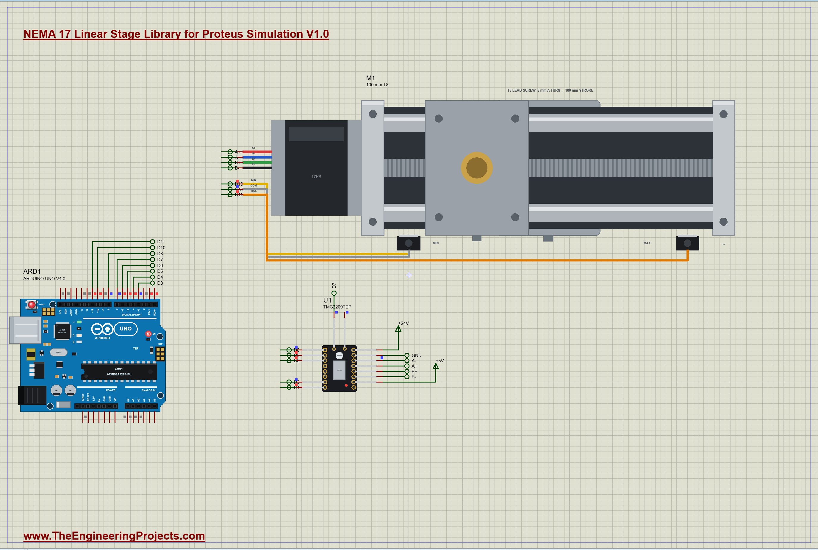
The stage is drawn at its true size from the top, the motor, the two end plates, the rods, the screw and the carriage with its brass nut, and at run time the carriage really slides along the sheet as the motor turns. The simulation model solves the motor's two coils with the driver, turns the rotor through its 50 teeth, and moves the carriage 8 mm for every turn of the screw. In the demo an Arduino homes the stage on its MIN switch and then moves it to three positions through our TMC2209 driver.
NOTICE: Our team has put a lot of effort into these small parts: the bodies, the animation and the pop-ups are all our own design, and you get them free. Your feedback is the fuel that keeps us going, so please tell us what you think in the comments below or in the Motor Driver board of our forum. And if our free libraries help you, you can buy us a coffee. So, let's get started with the NEMA 17 Linear Stage Library for Proteus Simulation:
What is a Linear Stage?
A linear stage turns the rotation of a motor into a straight movement. The common hobby version, the one this library draws, is a NEMA 17 stepper motor fixed to an aluminium end plate, a lead screw running from the motor to a second plate, and a carriage that slides on two 8 mm steel rods. A brass nut in the carriage rides on the screw: as the motor turns, the nut cannot turn with it, so it walks along the thread and takes the carriage with it. The same idea moves the Z axis of most 3D printers, the head of a pen plotter, the bed of a small engraver and the camera of a motorised slider.
Two small microswitches complete it. A stepper motor has no idea where it is when the power comes on, so the controller drives the carriage towards one switch until it closes and calls that point zero. From then on it counts every pulse it sends, and the second switch catches a move that would otherwise run into the far plate.
| The 100 mm NEMA 17 linear stage (this class) | |
|---|---|
| Motor | NEMA 17 of the 17HS4401 class: 1.8 deg (200 full steps a turn), 1.7 A, 1.5 ohm, 2.8 mH, 0.40 N.m holding |
| Screw | T8, a 4-start thread with an 8 mm lead: one turn moves the carriage 8 mm |
| Resolution | 40 microns a full step; 400 pulses a millimetre at 16 microsteps |
| Travel | 100 mm between the plates |
| Carriage | 0.3 kg on two 8 mm rods, plus the PAYLOAD property |
| Switches | MIN and MAX, each closing to COM within 2 mm of its end |
How a Lead Screw Turns Steps into Millimetres
The numbers of a lead-screw stage are simple, and they are worth knowing before you write a sketch. The lead is how far the nut moves in one turn of the screw. A T8 screw is 8 mm across with a 2 mm pitch, but it has four separate threads side by side, so its lead is 8 mm. The motor makes 200 full steps a turn, so one full step moves the carriage 8 / 200 = 0.04 mm. A driver set to 16 microsteps splits each full step into 16, which makes 3200 pulses a turn and 400 pulses a millimetre: 2.5 microns for every pulse from the Arduino.
The screw also multiplies the force. The ideal thrust is 2 pi times the torque divided by the lead, but a plastic or brass nut on a fast thread loses a good part of it to friction; our simulation model uses 45 percent, our figure for a 4-start nut, plus 6 mN.m of drag in the bearings. Even so, a few tens of mN.m at the motor become several newtons at the carriage. A coarse lead is fast, 8 mm a turn means 40 mm/s at 300 RPM, but it can also be pushed backwards: a vertical stage with an 8 mm lead slides down by itself when the driver lets go of the motor.
Speed costs torque, and that is the real limit of any stepper stage. As the motor turns faster, its coils generate a back-EMF against the supply, and the driver can push less and less current through them. That is why stages run their drivers on 24 V: the higher voltage keeps the current up at speed. Our model solves each coil, its resistance, its inductance and its back-EMF, together with the driver, so the current you see in the pop-up is the current the supply can really push.
Why a Stepper Stage Needs Homing
A stepper moves by counting, not by measuring. After power-up the sketch knows nothing about the carriage, so every stage program starts with homing: move towards the MIN switch at a moderate speed until it closes, back off a few millimetres, then approach again very slowly. The slow second touch matters because a switch closes a little later at speed, and the carriage keeps moving while the program reacts; at 2 mm/s that error is a few microns. The point where the switch closes on that second touch becomes zero.
Note that zero is where the switch closes, not where the carriage touches the plate. In this stage the MIN switch closes 2 mm before the plate, so the sketch's 0 mm is the pop-up's 2 mm, and every position the sketch asks for lands 2 mm further along the track. Real machines work the same way: the switch defines the origin, and the machine's soft limits keep the moves inside the travel.
Features of the NEMA 17 Linear Stage Library for Proteus Simulation
- The stage at true scale: a top view of the 100 mm stage, the motor, the two plates, the rods, the screw, the carriage with its brass nut and the two microswitches; at run time the carriage moves along the sheet and the screw's thread turns.
- Real coils: each coil is 1.5 ohm and 2.8 mH with its back-EMF, solved with whatever driver you connect, so the current falls at speed as on the bench.
- A real rotor: 50 teeth, the detent at the full steps, the inertia of the rotor and the screw; past its torque the rotor slips and the pop-up counts the full steps lost.
- The screw and the carriage: the 8 mm lead, 45 percent efficiency, the drag, the carriage's 0.3 kg plus PAYLOAD, horizontal or vertical (ORIENT).
- The ends: the carriage stops hard against the plates at 0 and 100 mm; MIN and MAX close to COM within 2 mm of their ends, so they wire straight to Arduino inputs with pull-ups.
- A pop-up: the carriage on its track with the switches, a scope of the two coil currents, the field against the rotor's teeth, eight live values, graphs, an event log and a check page.
- A complete package: about 1.2 MB with the library, our Arduino UNO V4.0 and the demo, without the source code of the model.
The NEMA 17 Linear Stage in Proteus
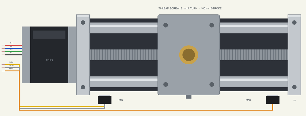
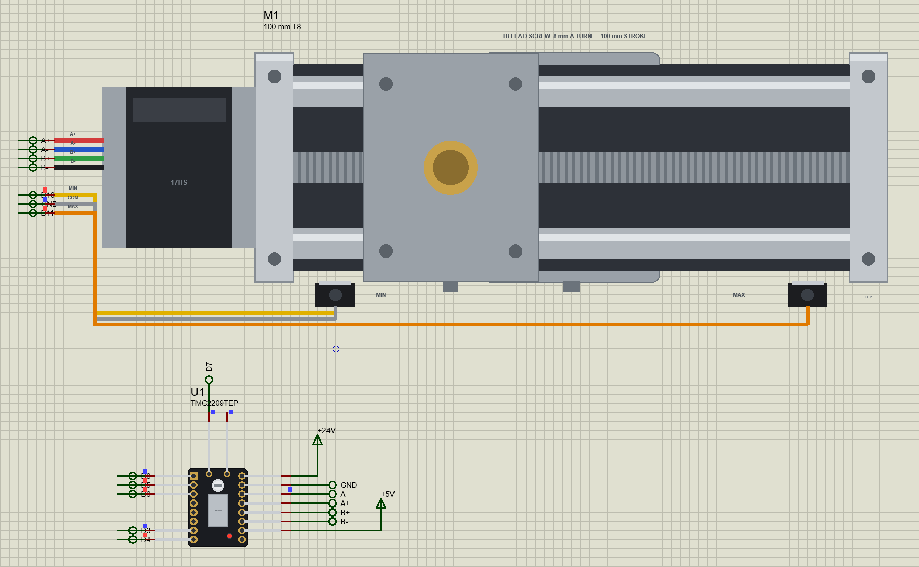
The device is STAGE100TEP in TEPLINSTAGE.LIB, under Electromechanical > Motors, with the prefix M and the analog model TEPLINSTAGE.DLL. Search STAGE100 in Pick Devices. Its pins are on the left: A+, A-, B+ and B-, the motor's two coils, for any two-coil stepper driver, and MIN, COM and MAX, the two switches and their common. The properties are START, where the carriage stands when the simulation starts (50 mm), PAYLOAD, the mass on the carriage (0.5 kg), and ORIENT, Horizontal or Vertical.
Download NEMA 17 Linear Stage Library for Proteus Simulation
Click the button below to download NEMA-17-Linear-Stage-Library-for-Proteus-v1.0.zip (about 1.2 MB, without the source code of the models):
NEMA 17 Linear Stage Library for Proteus V1.0- README.txt: installation, the demo, the wiring, troubleshooting and the limits of the simulation.
- Proteus Library Files:
TEPLINSTAGE.LIBandArduinoV4TEP.LIB. - Proteus Model Files:
TEPLINSTAGE.DLLandTEPARDUINO.DLL. - Arduino Code: the demo sketch.
- Proteus Simulation: the demo project, its HEX file and copies of the DLLs.
No Proteus yet? Read How to Download and Install Proteus 7 and 8. New to libraries? Follow How to Install a New Library in Proteus.
How to Install NEMA 17 Linear Stage Library for Proteus Simulation
- Close Proteus and extract the whole zip file, for example to your Desktop.
- Copy the files from Proteus Library Files into the LIBRARY folder of Proteus.
- Copy the files from Proteus Model Files into the MODELS folder.
- Delete
TEPLINSTAGE.IDXfrom the LIBRARY folder if it is there. - The demo's driver is our separate TMC2209 Stepper Driver Library for Proteus Simulation: install its LIB and DLL too.
- Start Proteus, press P and search for STAGE100.
Proteus Simulation of the Linear Stage with Arduino and TMC2209
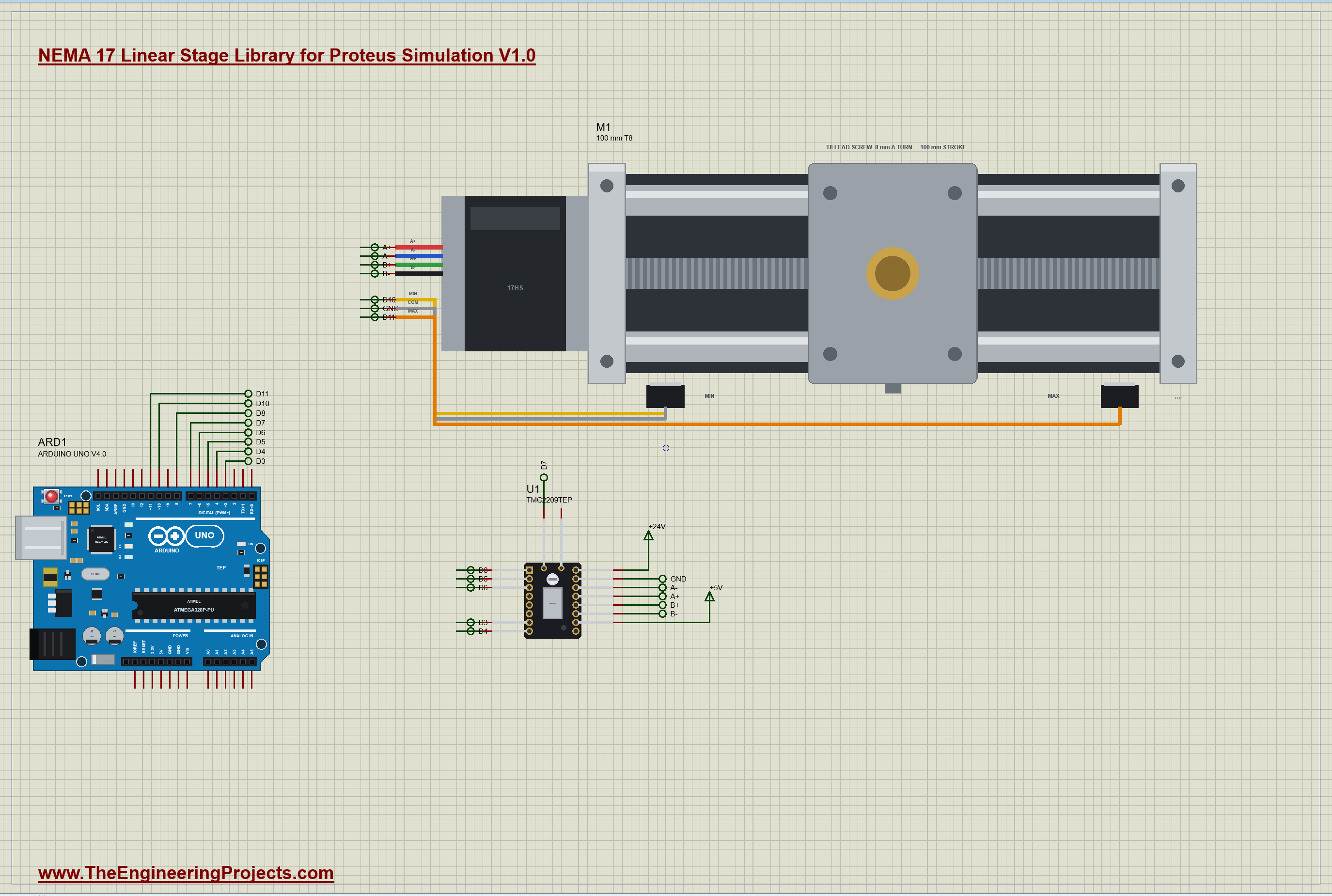
The demo has our Arduino UNO Library for Proteus V4.0 with its built-in monitor, the same window as our TEP Serial Monitor Advance for Proteus. The stage is driven by U1, the TMC2209 module from our separate TMC2209 library (TEPTMC2209.LIB and TEPTMC2209.DLL), so install it first. The TMC2209 is the quiet driver of most new 3D printers: its VM is on 24 V and its VDD on 5 V, its A1, A2, B1 and B2 go to the stage's A+, A-, B+ and B-, and the UNO gives it STEP on D3, DIR on D4 and EN on D8. MS1 and MS2 are on D5 and D6, both high for 16 microsteps, and its DIAG output comes back to D7. The stage's MIN switch goes to D10, MAX to D11 and COM to ground, read with the UNO's pull-ups. Open STAGE100-TMC2209-ArduinoUnoV4.pdsprj.
The Sketch
The pulses come from Timer1, which interrupts once for every pulse. The interrupt sends one pulse to STEP and counts it in pos, the carriage's position in pulses from home:
ISR(TIMER1_COMPA_vect) {
  if (toGo == 0) return;
  digitalWrite(STEP_PIN, HIGH);
  pos += dirStep;
  if (toGo > 0) --toGo;
  digitalWrite(STEP_PIN, LOW);
}
Homing is three phases in the loop. While seeking, the carriage runs towards MIN at 20 mm/s; the moment the switch reads LOW, the sketch stops and backs off 3 mm at 5 mm/s:
if (phase == SEEK && digitalRead(MIN_PIN) == LOW) { halt(); startPulses(3 * PER_MM, 1, 5); phase = BACKOFF; say(F("MIN closed - backing off 3 mm")); }Then it creeps back at 2 mm/s, and where MIN closes again the position counter is set to zero:
halt(); noInterrupts(); pos = 0; interrupts(); homed = true; phase = PLAN; moveIdx = 0; say(F("HOMED: this point is 0"));After homing the sketch runs its plan, each move 400 ms after the last one ends, with a ramp of 100 mm/s squared: to 50 mm at 30 mm/s, to 90 mm at 40 mm/s and back to 10 mm at 40 mm/s:
const Move PLAN_MOVES[] = { {50, 30}, {90, 40}, {10, 40} };Afterwards you can type g 25 in the monitor to go to 25 mm, or h to home again.
Linear Stage Simulation Results
Open the project and press Run. The program runs about 12 simulated seconds; with both pop-ups open and the pictures being taken it took about three and a half minutes on our PC. Click the stage to open its pop-up, and the TMC2209 for the driver's. Every number below comes from one simulation run, the demo exactly as it ships.
Homing on the MIN Switch
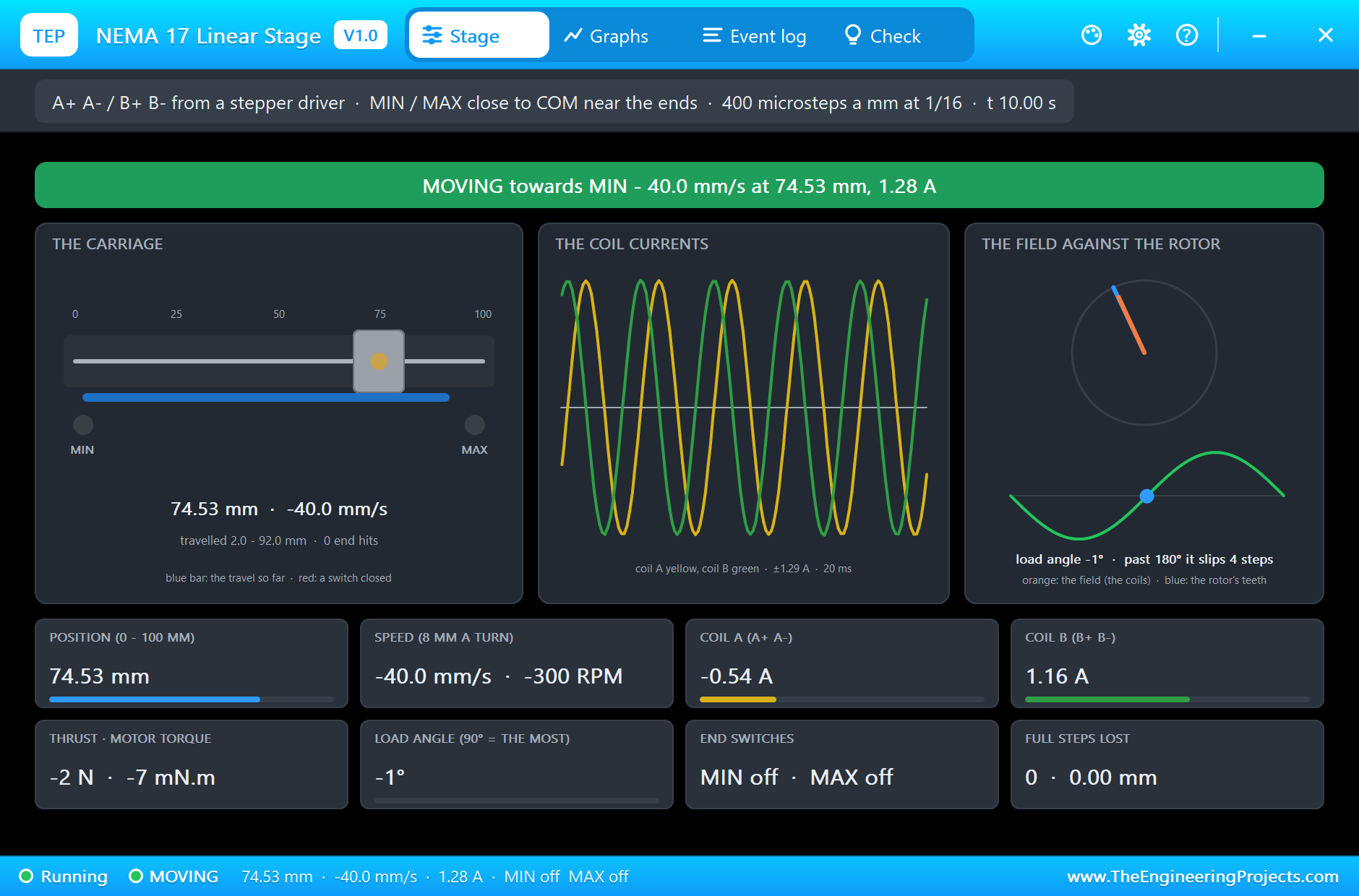
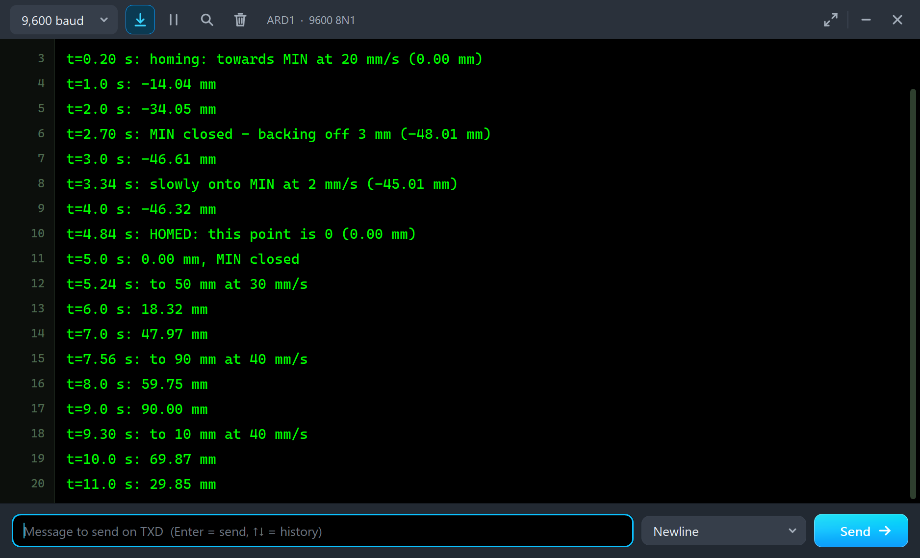
At 0.2 s the UNO enables the driver and starts homing. At 1.2 s the banner reads MOVING towards MIN: 20.0 mm/s, 150 RPM, the carriage at 33.28 mm with 1.32 A in the coils. The scope shows the two coil currents a quarter of a turn apart, over the last 32 ms, and the motor needs only 7 mN.m to turn the screw against its drag. Note the monitor: before homing, the sketch counts from wherever it started, so it prints negative millimetres.
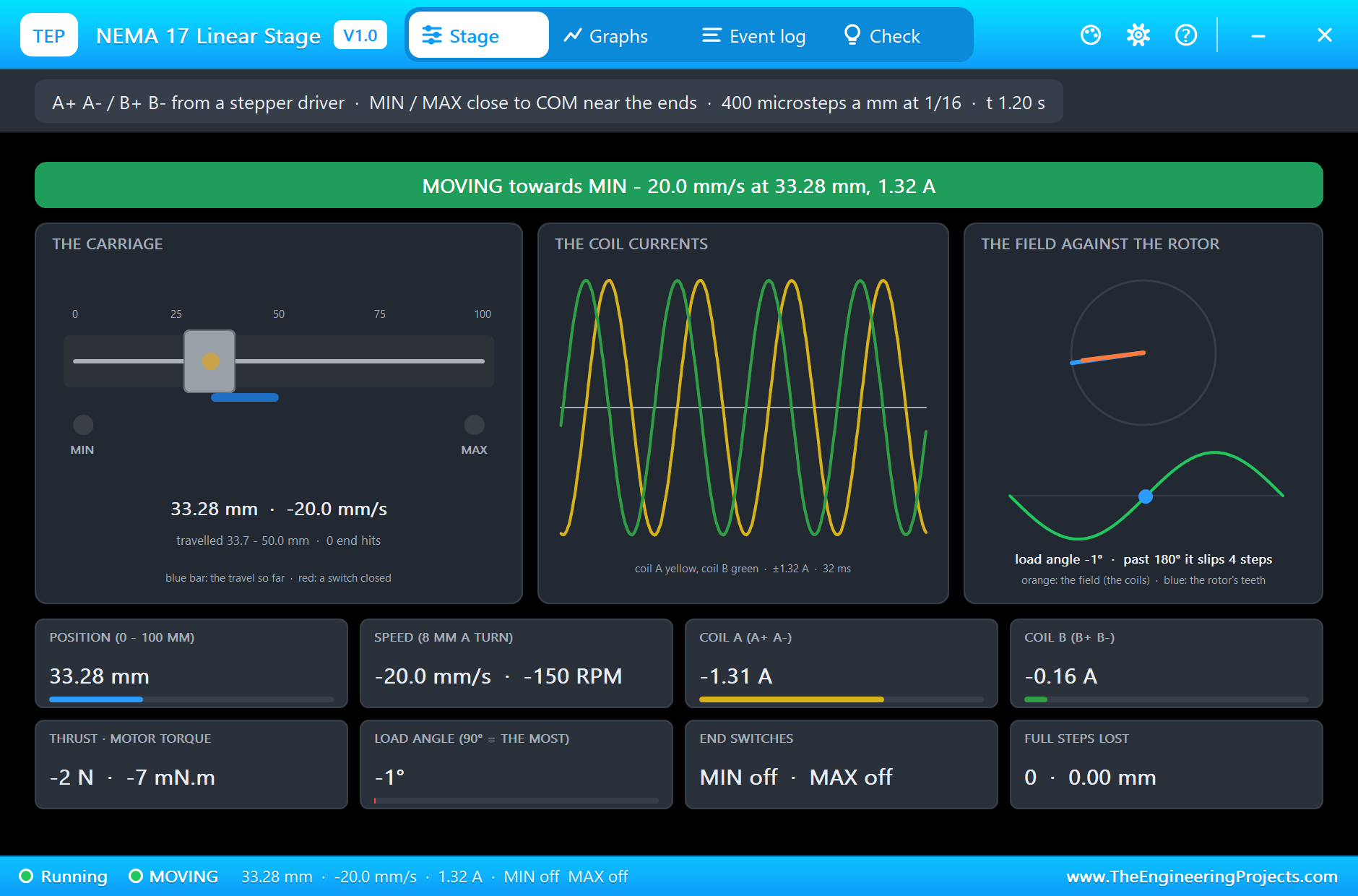
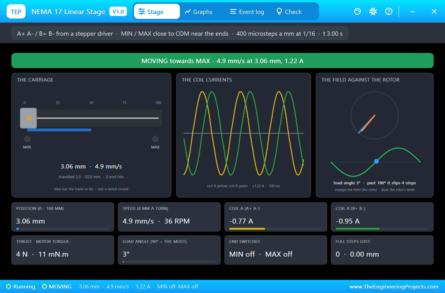
At 2.70 s MIN closes, after 48.01 mm of travel, and the sketch reverses at once. At 3 s the carriage is backing off at 4.9 mm/s, 3.06 mm from the plate; the motor pushes 4 N for a moment, 11 mN.m, to get the carriage moving the other way.
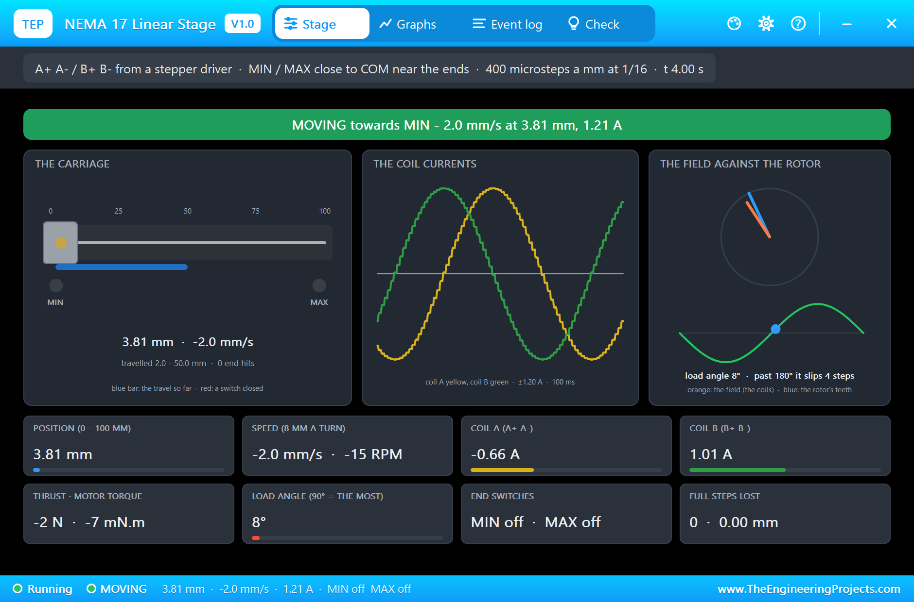
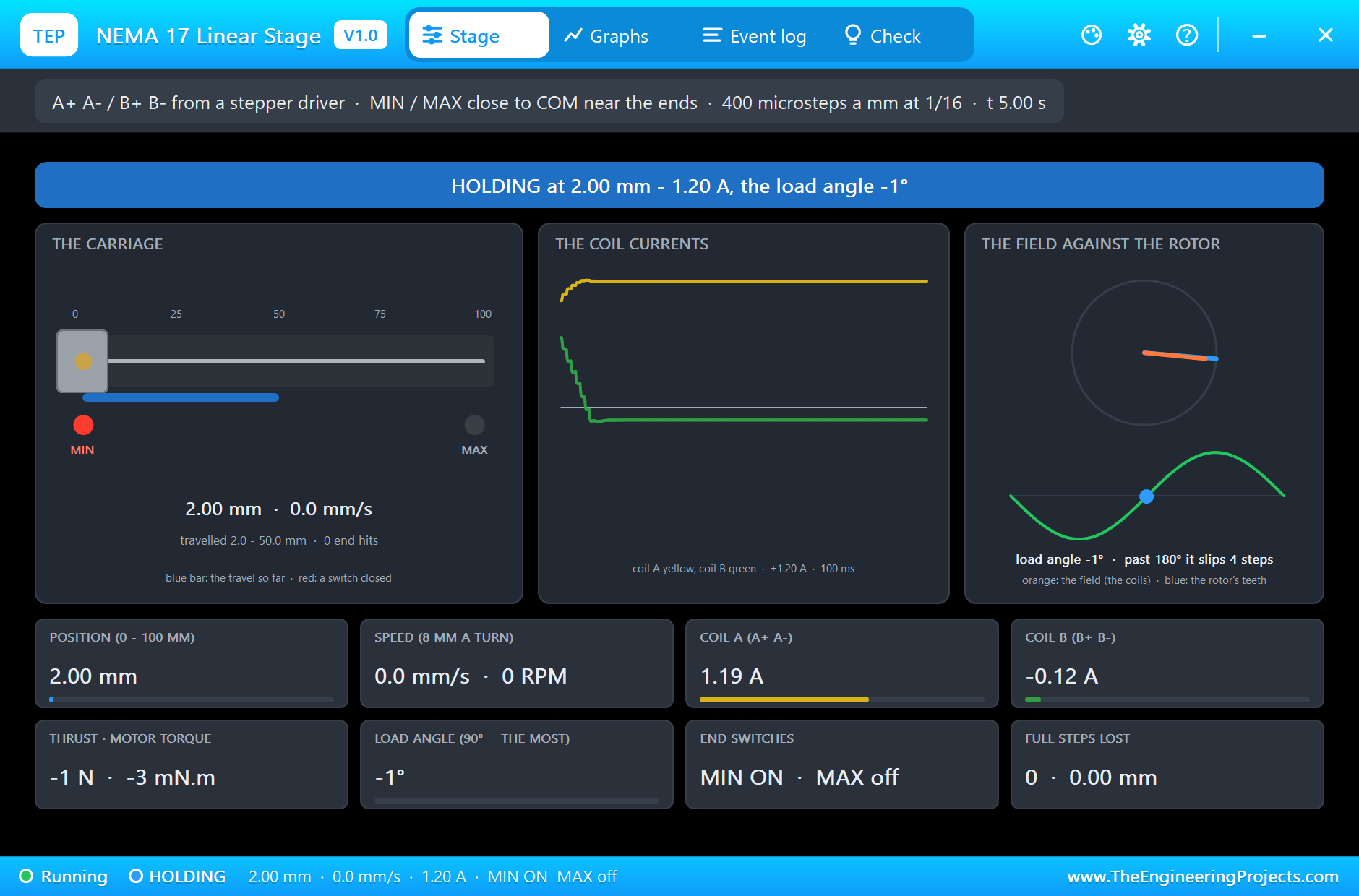
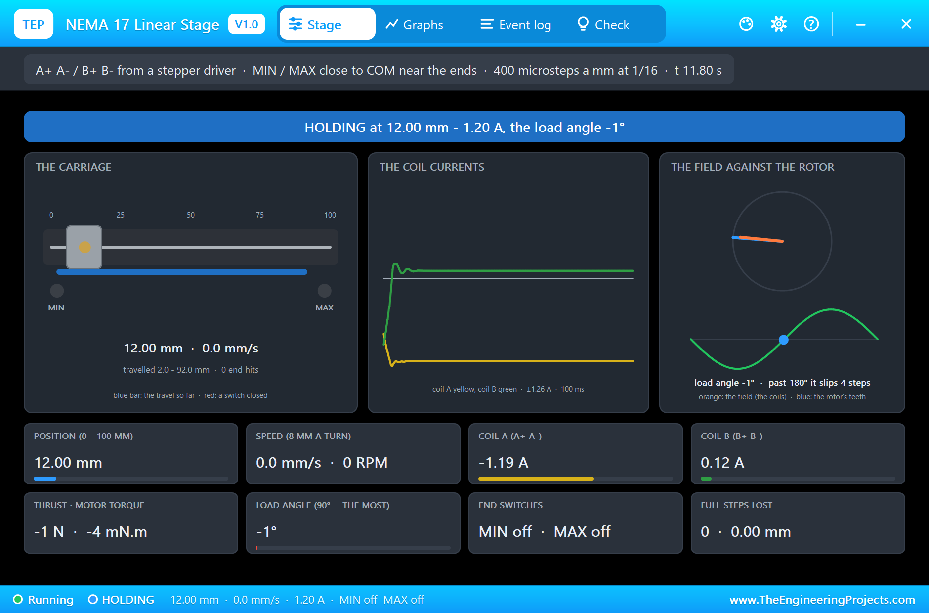
Then it creeps back at 2.0 mm/s. At this crawl the rotor is pulled from detent to detent, and the load angle on the field card swings to 8 degrees, still far from the 90 degrees where it would slip. At 4.84 s MIN closes again and the sketch sets its counter to zero. The banner turns blue, HOLDING at 2.00 mm with 1.20 A, and the MIN switch is lit red: the sketch's zero is 2 mm from the plate, as described above.
To 50 mm at 30 mm/s
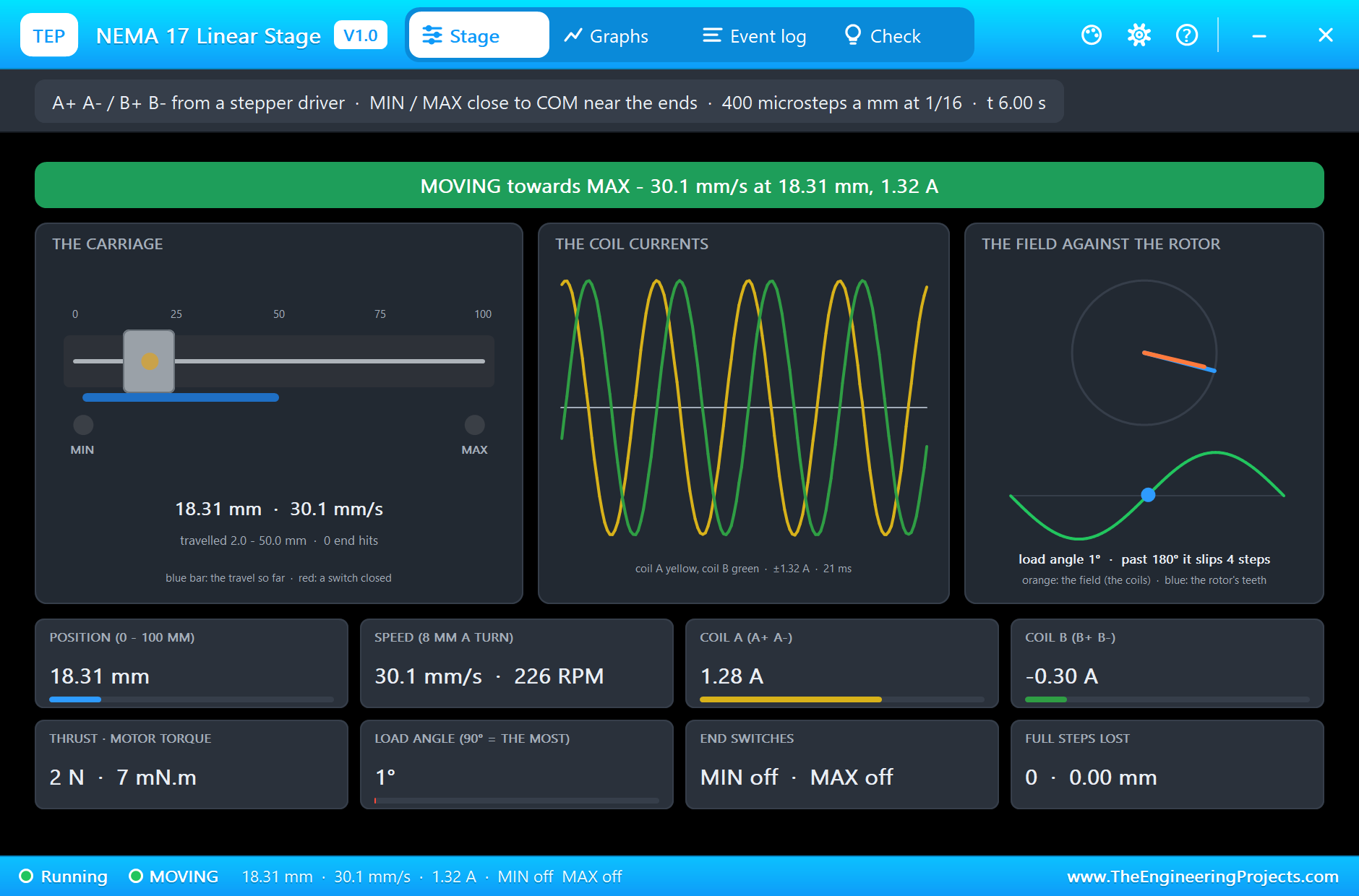
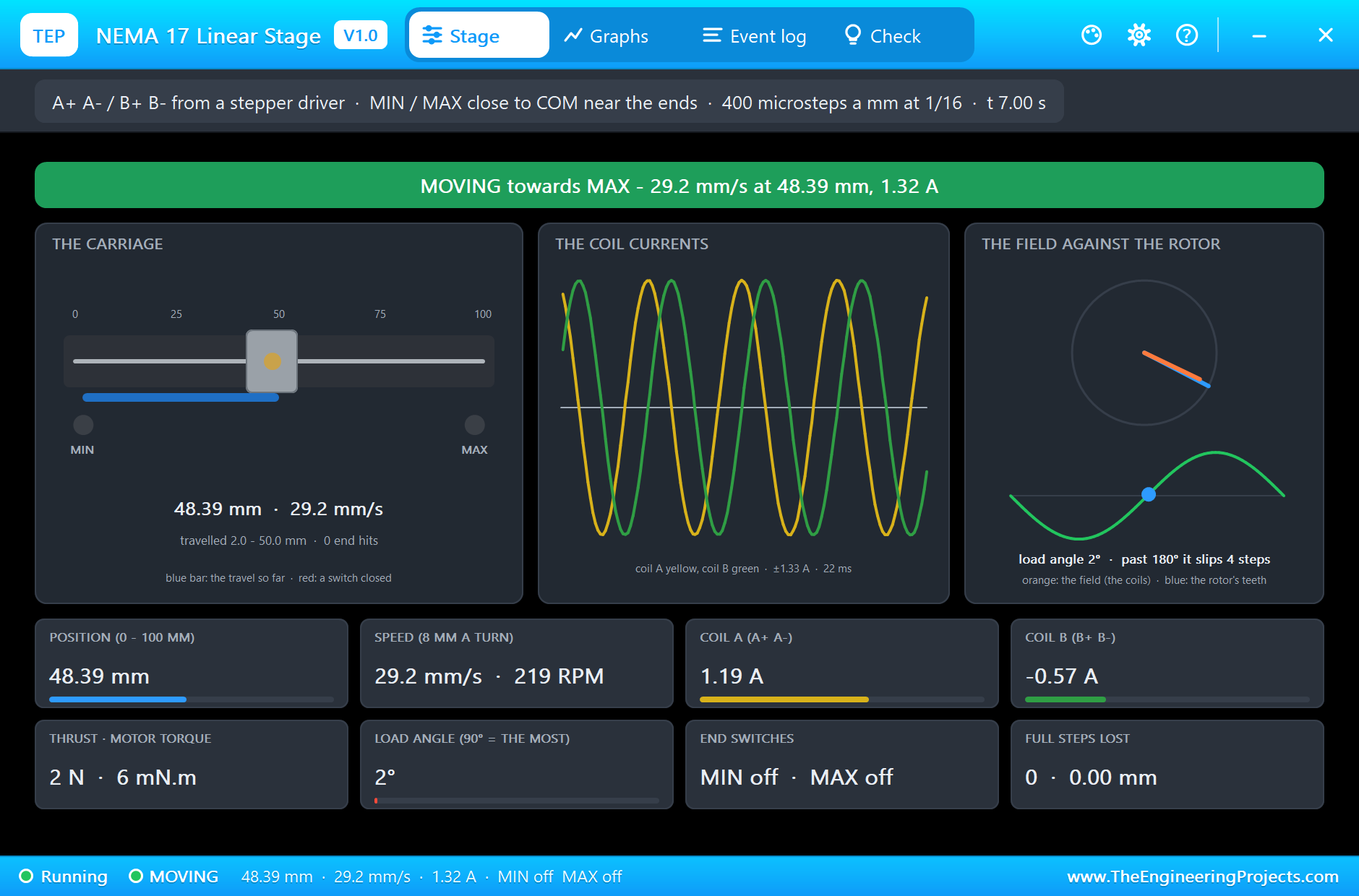
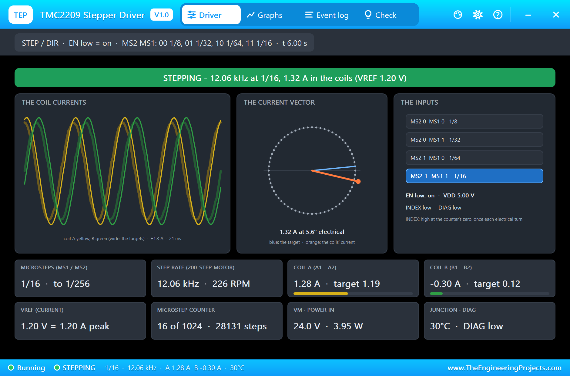
At 5.24 s the UNO starts the first move. At 6 s the carriage runs at 30.1 mm/s, 226 RPM, at 18.31 mm, with 1.32 A, 2 N of thrust and 7 mN.m at the motor. That is 12.06 thousand pulses a second from the UNO; the TMC2209's pop-up shows the same rate and its two coil currents following their targets. At 7 s the ramp is slowing the carriage, 29.2 mm/s at 48.39 mm, and the Event log notes it holding at 52.00 mm: the sketch's 50 mm.
To 90 mm and Back to 10 mm
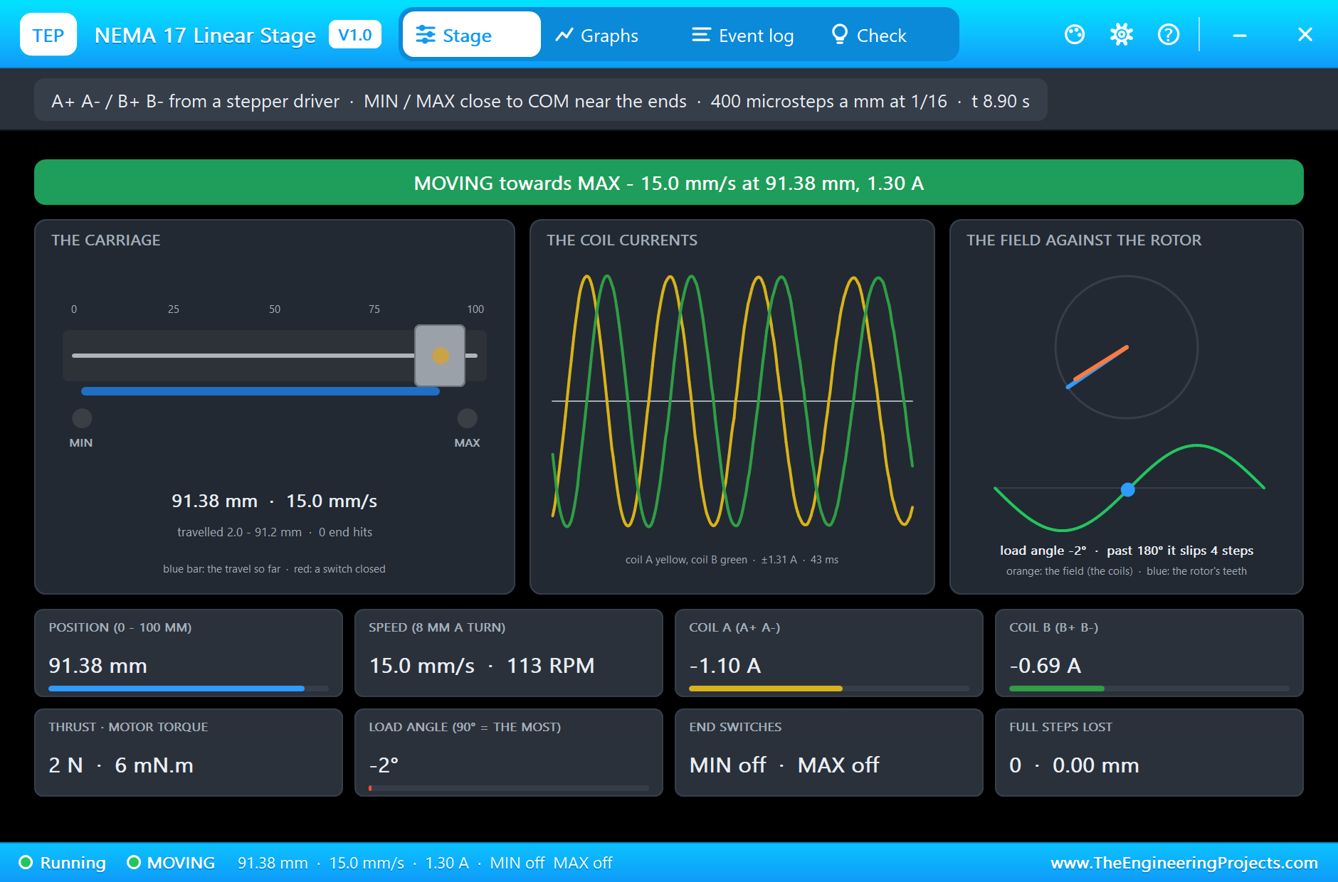
At 7.56 s it sets off for 90 mm at 40 mm/s, 300 RPM, with 1.28 A. At 8.9 s it is slowing down, 15.0 mm/s at 91.38 mm, and it stops at 92.00 mm, still well inside the MAX switch, which closes only past 98 mm. At 9.30 s it heads back to 10 mm; at 10 s it passes 74.53 mm at 40.0 mm/s. At 11.8 s it holds at 12.00 mm with 1.20 A: the sketch's 10 mm, after 80 mm back. The FULL STEPS LOST tile still reads 0, and the load angle never came near 90 degrees: on 24 V the driver kept the current up at every speed of the demo.
The Graphs, the Event Log and the Check Page
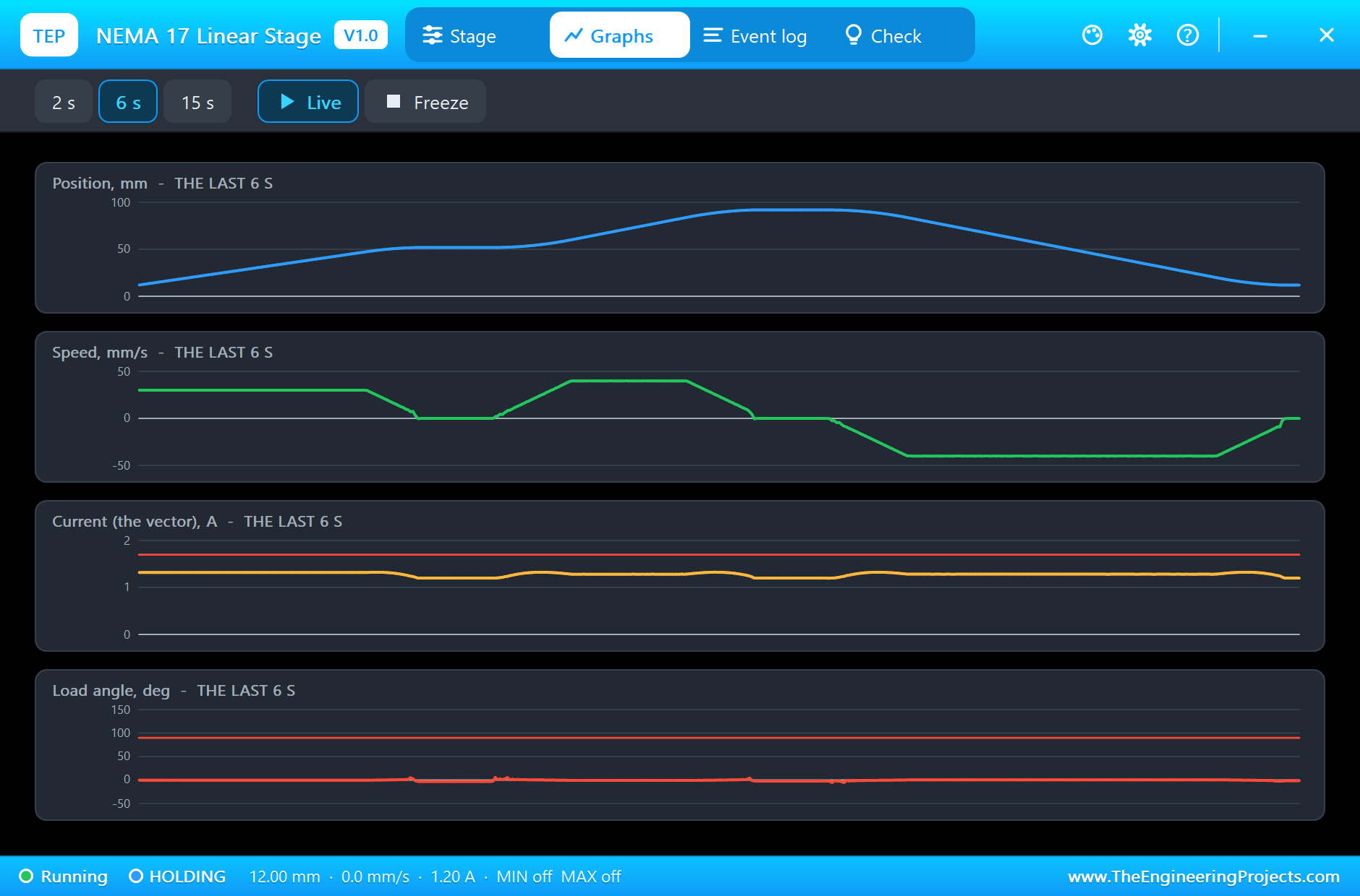
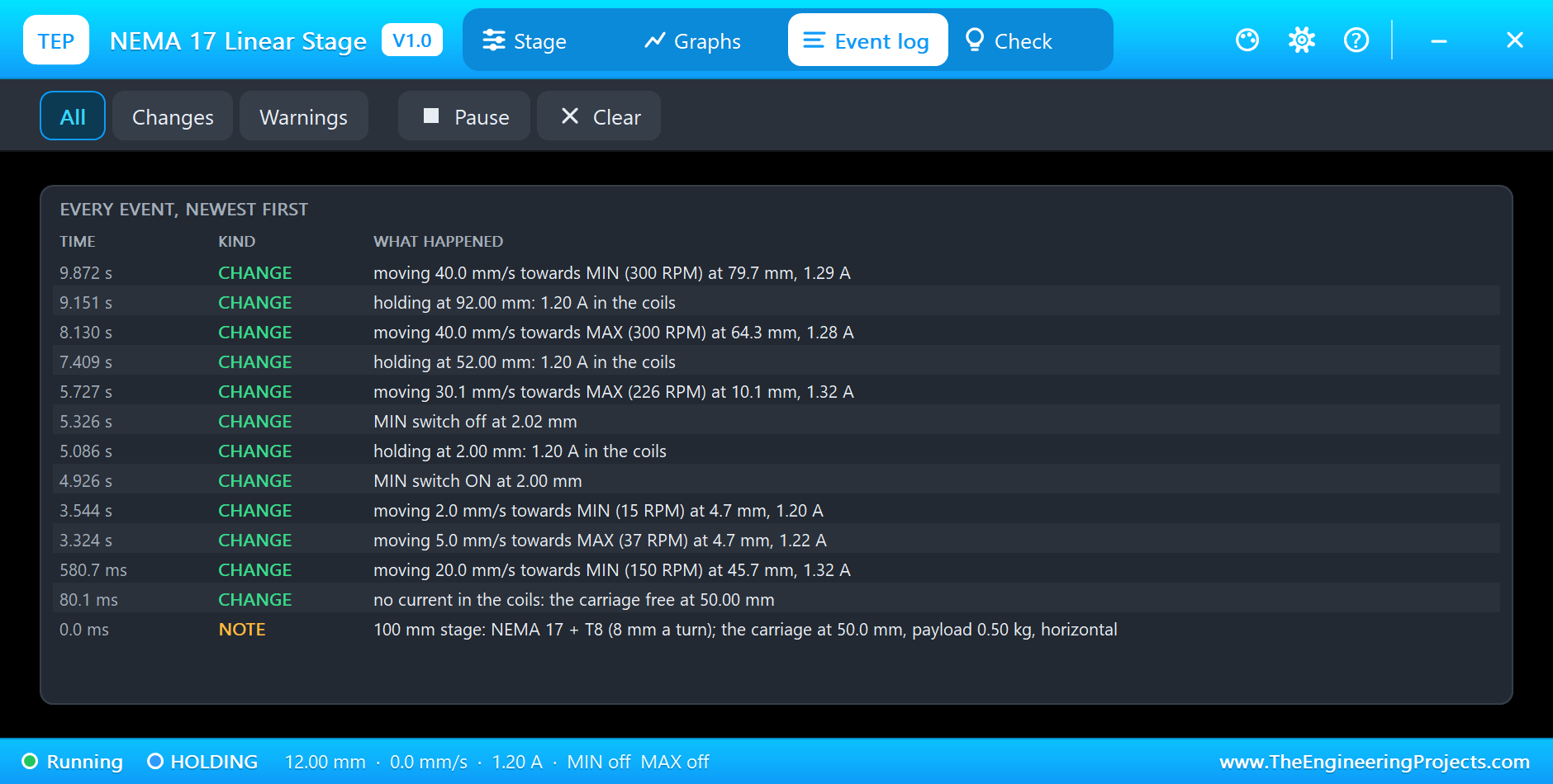
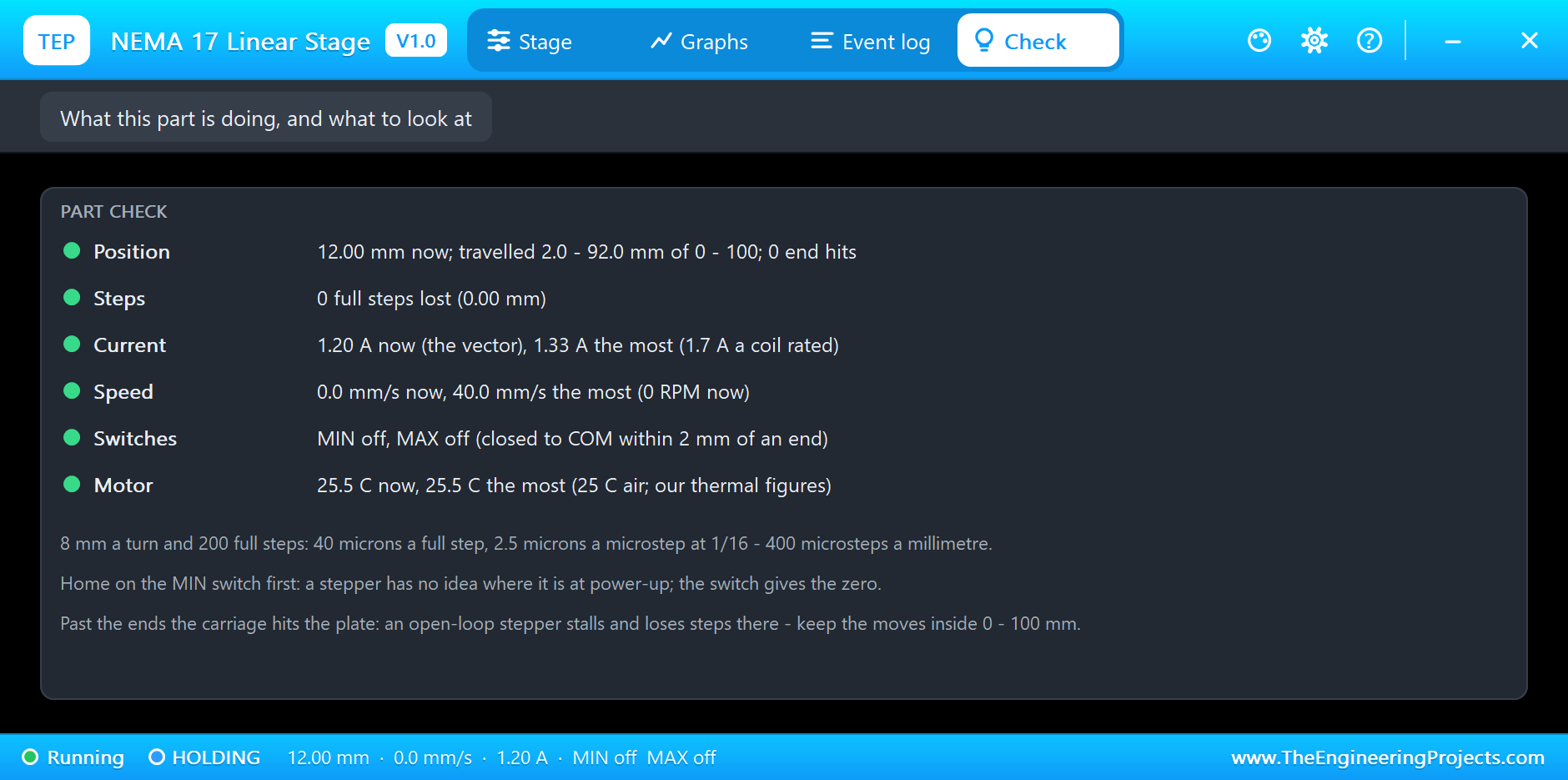
The Graphs page plots the position, the speed, the current and the load angle over the last 2, 6 or 15 simulated seconds; the three moves show as clean trapezoids of speed and smooth S-curves of position. The Event log keeps every change: the homing moves, the MIN switch on and off, the holds at 52, 92 and 12 mm. The Check page ends the run green: travelled 2.0 to 92.0 mm, no end hits, no steps lost, 1.33 A at the most and the motor at 25.5 C.
Try It Yourself
- Type
g 95in the monitor: the carriage stops at 97 mm on the track, and MAX stays open; change the sketch's limit to 99 and watch MAX close and the carriage hit the plate. - Set ORIENT to Vertical and PAYLOAD to 2 kg: the thrust tile now shows the weight, and the load angle grows on the way up.
- Lower VREF on the TMC2209 to 0.5 V: less current, less torque; watch the load angle grow in the moves, and find the speed where the stage starts to lose steps.
- Change START to 1: the carriage starts with MIN already closed, so the first seek ends at once and the sketch backs off straight away.
- Change the microsteps to 1/8 in the sketch and on MS1 / MS2: 200 pulses a millimetre, the same moves with half the pulses.
Ideas to Extend the Demo
- Add a second stage on another driver: an X-Y table that draws a square.
- Read a potentiometer and move the carriage to follow it: a simple positioner.
- Use the MAX switch as a soft limit: stop any move the moment it closes.
Your Own Sketches
The demo sketch is in the zip file, and you can change it in the Arduino IDE. New to Arduino? Start with our Arduino Tutorial for Beginners. Export the compiled binary, and set the UNO's PROGRAM property to the new file. Our guide on How to get the HEX file from Arduino shows you where the file ends up.
Things to Know Before Using a Real Linear Stage
- Home every time: after power-up or a stall the position is unknown; never trust the count until the switch has been found.
- Set the current: the driver's VREF sets the torque; too little and the stage loses steps at speed, too much and the motor runs hot.
- Use 24 V for speed: the back-EMF of the motor limits the current at high speed far more on 12 V.
- Mind the vertical axis: an 8 mm lead back-drives; keep the driver enabled or add a counterweight or a brake.
Troubleshooting
- It does not move: no current in the coils (the driver's EN is high, or VM or VDD is missing), or the coils are not wired to A+ A- B+ B-.
- It moves the wrong way: swap the two wires of one coil, or invert DIR in the sketch.
- AT THE END: the carriage is against a plate; home on MIN first and keep the moves inside the switches.
- Steps lost: too fast for the current the supply can push, or a hit at an end.
- The part is not simulated:
TEPLINSTAGE.DLLis missing from MODELS and from the project folder.
Limitations of the Simulation
- The motor's data are those of the common 17HS4401 class; the screw's efficiency, the drag and the thermal figures are our estimates.
- The nut's backlash, the screw's whip at speed and the switches' bounce are not modelled.
- The driver's chopper ripple is averaged out; the coil currents are the driver's mean currents.
- Arduino is a name of Arduino; this library is not made or endorsed by Arduino, Labcenter or any stage, motor or driver maker.
- Tested in Proteus 8.5 in November 2026 (the demo as shipped). Proteus 7 is not supported.
So, that was all about the NEMA 17 Linear Stage Library for Proteus Simulation. I hope it helps you try a lead-screw axis in a simulation before you build one: the homing, the pulses a millimetre, the speed against the current and the switches at the ends, with a pop-up that shows the carriage, the coil currents and the rotor behind every move. If you have any questions, ask in the comments and I will help you out. Till the next tutorial, take care and have fun!