Hello friends, I hope you all are doing great. Today, I am going to share the SAM R21 Xplained Pro Library for Proteus, so you can run an IEEE 802.15.4 simulation of Microchip's wireless evaluation kit. The SAM R21 Xplained Pro carries the ATSAMR21, an Arm Cortex-M0+ with a 2.4 GHz 802.15.4 radio inside the same chip, the radio behind Zigbee, Thread and 6LoWPAN. With this library it runs your Arduino sketch in Proteus 8.5, sends and receives 802.15.4 frames between boards, and its LED and button work with a click.
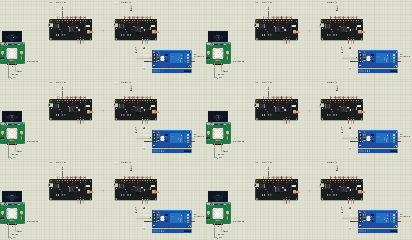
SAM R21 Xplained Pro Library for Proteus
Latest version: V1.0 (November 2026, this tutorial)
Other new Arduino boards: UNO R4 WiFi · Nano ESP32 · UNO WiFi Rev2 · Nano 33 IoT · UNO Q · UNO R4 Minima · Nano Every · MKR WiFi 1010 · Nano RP2040 Connect · STM32 Black Pill · Nucleo-F401RE · STM32 Blue Pill · Teensy 4.1 · Arduino Due · Arduino Leonardo · Arduino Micro · BBC micro:bit V2 · GIGA R1 WiFi · MKR WAN 1310 · Nano 33 BLE Sense · XIAO nRF52840 Sense · RAK4631 WisBlock · Nano Matter · nRF52840 DK · nRF5340 DK · nRF9151 DK · nRF7002 DK · Nordic Thingy:53 · xG24 Dev Kit · xG24 Explorer Kit · Thunderboard BG22 · SiWx917 Dev Kit · B-L475E-IOT01A · NUCLEO-WB55RG · NUCLEO-WL55JC1 · NUCLEO-H743ZI2
RF modules: nRF24L01 · nRF24L01 PA LNA · CC1101 · RFM69HCW · HC-12 · 433MHz RF · XBee
Temperature and weather sensors: DHT11 / DHT22 · DS18B20 · BME280 · BMP280 · SHT31 · AHT20 · BME680 · MLX90614 · MAX6675
Helping Tools
- Laptop WiFi Monitor: a laptop on the Wi-Fi of your design: a browser, a TCP / UDP terminal and ping
- Mobile WiFi Monitor: a smartphone that opens the pages of your board and sends it commands
- Serial Monitor Advance: a serial terminal window for the UART of your board
For the demo we built a wireless hall light and doorbell with two boards. A node by the front door has a PIR motion sensor and the doorbell button; the base switches the hall light with a relay and rings when someone presses the bell - no wires between them, just 802.15.4 frames.
NOTICE: Proteus has no ATSAMR21 model, so our team has put a lot of effort into building this board ourselves: the header, the LED, the button and the radio are all our own model, and your sketch compiles with our free TEP Boards for Proteus add-on. Your feedback is the fuel that keeps us going, so please tell us what you think in the comments below. And if our free libraries help you, you can buy us a coffee. So, let's get started with the SAM R21 Xplained Pro Library for Proteus:
What is the SAM R21 Xplained Pro?
The SAM R21 Xplained Pro (ATSAMR21-XPRO) is Microchip's evaluation kit for the SAM R21 family. Its ATSAMR21G18A combines an Arm Cortex-M0+ at 48 MHz, 256 KB of flash and 32 KB of RAM with the AT86RF233, a 2.4 GHz IEEE 802.15.4 transceiver, in one package. The black Xplained Pro board adds the Embedded Debugger (EDBG) with its micro-USB, which programs the chip and gives a virtual COM port, a ceramic chip antenna and an SMA socket for an external one, a yellow user LED (LED0), a user button (SW0), RESET and the Xplained Pro extension headers for sensor and display boards.
| Part | The real SAM R21 Xplained Pro | In the library |
|---|---|---|
| MCU | ATSAMR21G18A: Cortex-M0+ at 48 MHz | your Arduino sketch |
| Radio | AT86RF233, 2.4 GHz IEEE 802.15.4 | RF233: PAN ID, addresses, channels 11 to 26 |
| LED | LED0, yellow | LED0, lit when LOW |
| Buttons | SW0, RESET | SW0 (LOW when pressed), RESET |
| Headers | EXT1, EXT3, power | EXT1 pins 3 to 18 and the power header |
| Memory | 256 KB flash, 32 KB RAM | about 256 KB of flash, 8 KB of RAM |
What Is IEEE 802.15.4?
IEEE 802.15.4 is the radio standard for small, low-power networks. It runs at 250 kbit/s on sixteen channels between 2405 and 2480 MHz, numbered 11 to 26, and its frames are short, at most 127 bytes. Devices that belong together share a PAN ID, and each has a short 16-bit address. On top of 802.15.4 sit the well-known protocols: Zigbee for lights and sensors, Thread and 6LoWPAN for IP-based smart homes, and Microchip's own LwMesh and MiWi.
PAN IDs, Addresses and Channels
Three numbers decide who hears whom. The channel picks the frequency; boards on different channels never hear each other. The PAN ID names the network, so two networks on the same channel - for example the neighbour's - ignore each other's frames. The short address picks one device inside the network, and the address 0xFFFF reaches all of them at once. Our demo uses PAN 0x2121 on channel 15, the base is 0x0001 and the node is 0x0002.
The Xplained Pro Extension Headers
Every Xplained Pro board has the same 20-pin extension headers, so sensor, display and wireless boards from Microchip fit any kit of the family. Pin 1 is an ID line, pins 2 and 19 are ground, pin 20 is 3.3 V, and pins 3 to 18 carry two analog inputs, four general-purpose pins with PWM and an interrupt, I2C, a UART and SPI, always in the same order. Our board package gives each of them a name.
Why a Sensor Network?
A building or a field full of sensors does not need speed; it needs batteries that last for years and a radio that gets through walls. 802.15.4 nodes sleep most of the time, wake for a few milliseconds to send a reading, and go back to sleep. A small base collects the frames and acts on them or passes them to the internet. Our demo is the smallest such network: one node and one base.
The Reference Board of RIOT OS
The SAM R21 Xplained Pro is a favourite in research. It is the reference board of RIOT, the open-source operating system for the Internet of Things, and appears in many papers on low-power networking, 6LoWPAN and network security. Students and researchers use it because the radio and the microcontroller are in one well-documented chip, and the debugger is on the board.
Where Is It Used?
The SAM R21 family powers smart-home devices, lighting control, building automation, wireless sensor networks for farms and factories, and asset tracking. For other wireless boards from the same family of libraries, see our NUCLEO-WL55JC1 Library for Proteus with LoRa and our NUCLEO-WB55RG Library for Proteus with Bluetooth LE.
A simulation lets you build the protocol of a sensor network before the boards are on the desk: the frames, the addresses, the confirmations and the repeats. When the logic works in the Proteus simulation, the real boards only have to confirm it.
Features of the SAM R21 Xplained Pro Library for Proteus
- The board as it looks: the black Xplained Pro PCB with the EDBG and its USB, the ATSAMR21, the radio's crystal and balun, the RF line to the chip antenna and the SMA socket, LED0, SW0, RESET, the EXT1 header and the power header, drawn compact, with our small TEP signature.
- Your sketch: a .hex for "Microchip SAM R21 Xplained Pro (TEP Proteus)" with clear names for every EXT1 pin (EXT1_PIN_3 to EXT1_PIN_18, EXT1_GPIO1, EXT1_PWM_P and more), LED0 and SW0.
- 802.15.4: our RF233 library with a PAN ID, short addresses and channels 11 to 26; frames to one board or to every board of the PAN, with RSSI and LQI.
- Real LED and button: LED0 lights yellow when LOW, as on the real board; SW0 is clicked on the board.
- A complete package: about 4.2 MB with the part, the add-on, the PIR sensor, the relay and the two-board demo, without the source code of the models.
The SAM R21 Xplained Pro in Proteus Simulation
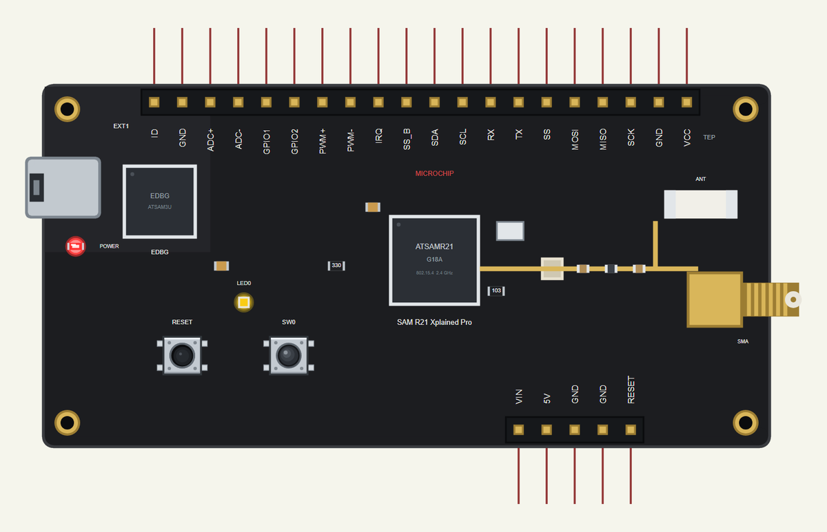
Search SAMR21 in Pick Devices; the device is in TEPSAMR21.LIB (Microprocessor ICs, 802.15.4 Boards), with the prefix U. The EDBG's USB opens the serial monitor.
The Pins
| Pins | What the library does with them |
|---|---|
| ADC+, ADC- | EXT1 3 and 4: analogRead 0 to 1023 for 0 to 3.3 V, or GPIO |
| GPIO1 to IRQ | EXT1 5 to 9: GPIO, PWM with analogWrite, attachInterrupt |
| SDA, SCL | EXT1 11 and 12: Wire, the I2C bus |
| RX, TX | EXT1 13 and 14: Serial1 |
| SS to SCK | EXT1 15 to 18: SPI |
| LED0, SW0 | the yellow LED (lit when LOW) and the user button (LOW when pressed) |
Microchip makes no Arduino core for this kit, so the board package uses the names of the Xplained Pro standard, which every extension board for the kit follows.
Download SAM R21 Xplained Pro Library for Proteus
Click the button below to download SAM-R21-Xplained-Pro-Library-for-Proteus-v1.0.zip (about 4.2 MB, without the source code of the models):
SAM R21 Xplained Pro Library for Proteus V1.0- README.txt: installation, the demo, the pins, the properties, troubleshooting and the limits.
- Proteus Library Files:
TEPSAMR21.LIB, the PIR sensor and the relay:TEPHCSR501.LIBandTEPRELAY.LIB. - Proteus Model Files:
TEPNET.DLL,TEPHCSR501.DLLandTEPRELAY.DLL. - Arduino Code: the two demo sketches and the TEP Boards for Proteus add-on 1.73.0, with RF233.
- Proteus Simulation: the demo project, its two HEX files and copies of the DLLs.
No Proteus yet? Read How to Download and Install Proteus 7 and 8. New to libraries? Follow How to Install a New Library in Proteus.
How to Install SAM R21 Xplained Pro Library for Proteus
- Close Proteus and extract the whole zip file, for example to your Desktop.
- Copy the files from Proteus Library Files into the LIBRARY folder of Proteus.
- Copy the DLLs from Proteus Model Files into the MODELS folder, replacing an older
TEPNET.DLL. - Delete
TEPSAMR21.IDXfrom the LIBRARY folder if it is there. - For your own sketches, copy Arduino Code\TEP Boards for Proteus\hardware into your Arduino sketchbook (Documents\Arduino) and restart the Arduino IDE; the board is Microchip SAM R21 Xplained Pro (TEP Proteus).
- Start Proteus, press P and search for SAMR21.
Demo: an 802.15.4 Hall Light and Doorbell in Simulation
Running a cable from the front door to the light switch and the bell is a job for an electrician. Two small radio boards do it without a single wire: the node by the door watches the hall with a PIR sensor and has the doorbell button, and the base, near the light, switches a relay and rings. Battery nodes like this one are the everyday use of 802.15.4.
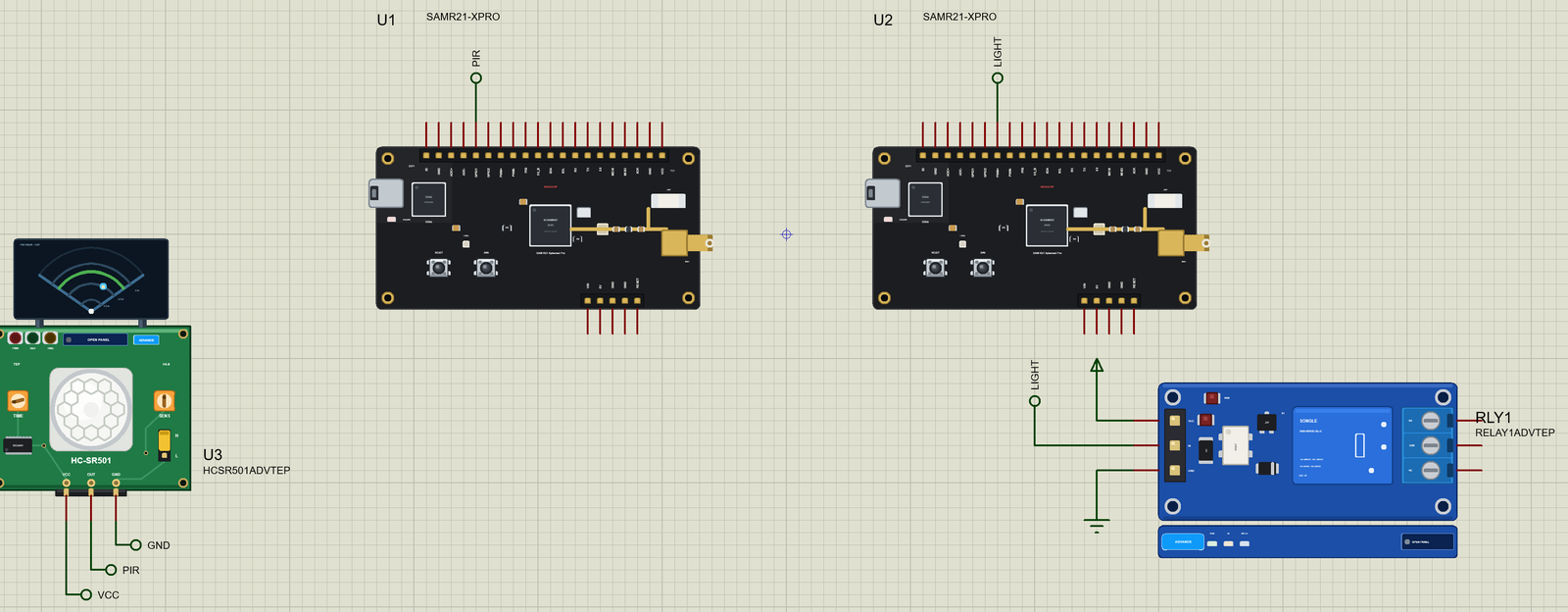
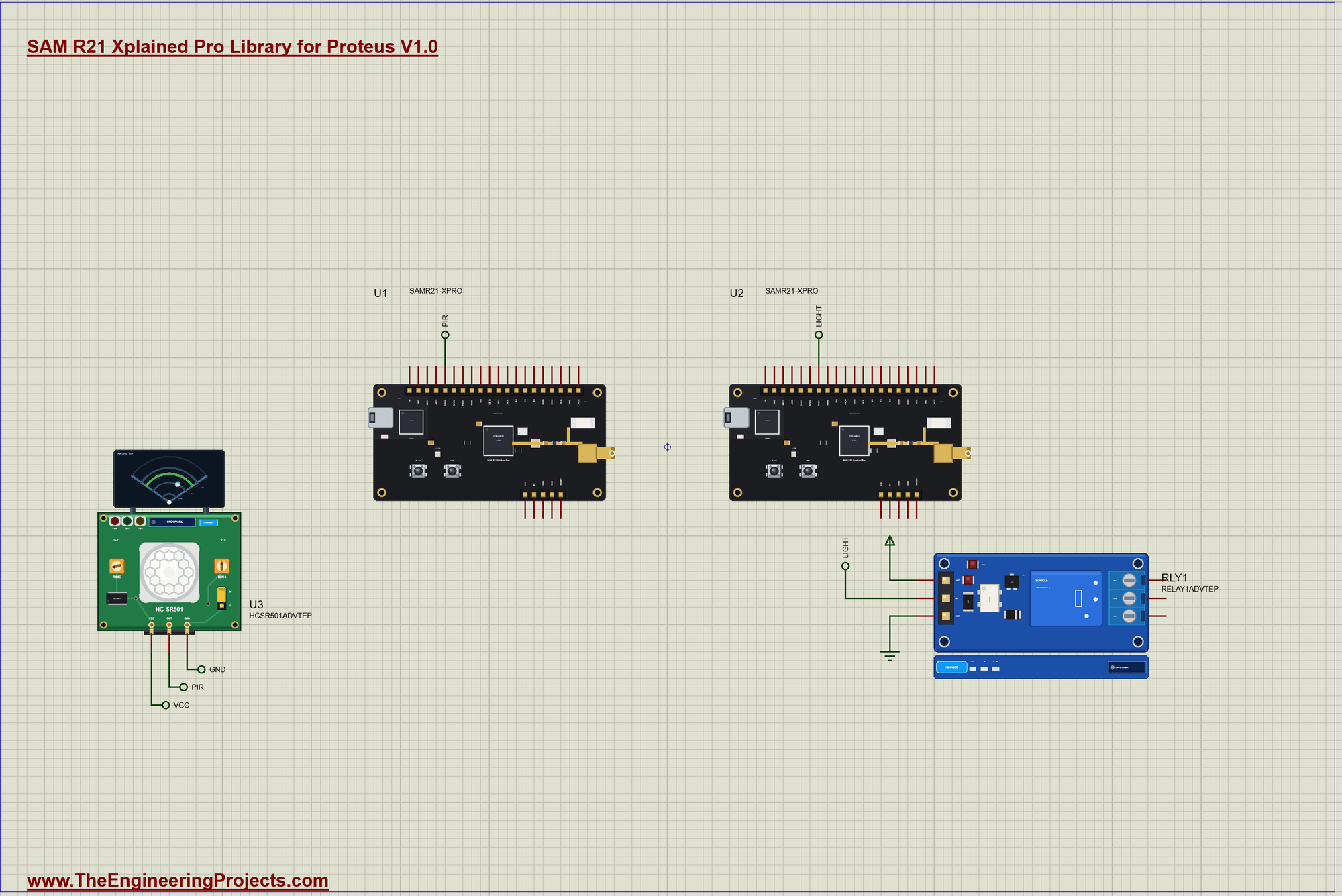
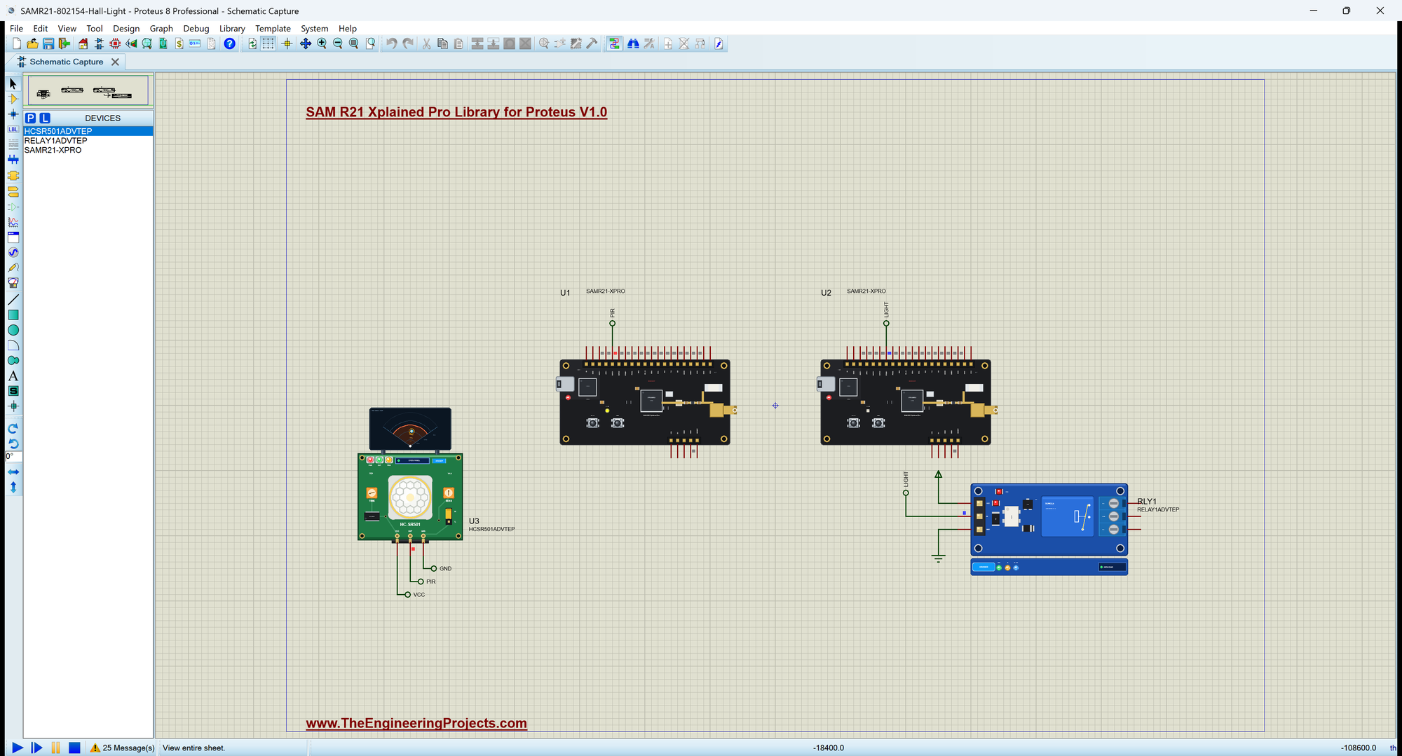
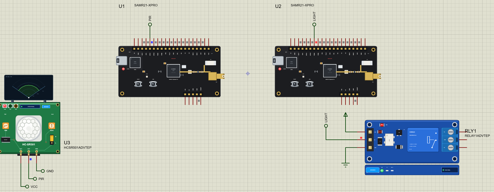
Open SAMR21-802154-Hall-Light.pdsprj. U1 runs SAMR21_Hall_Node.hex (address 0x0002) with the HC-SR501 PIR sensor U3 on EXT1 pin 5. U2 runs SAMR21_Hall_Base.hex (address 0x0001) with the hall light's relay RLY1 on EXT1 pin 7. Both use PAN 0x2121 on channel 15. The serial monitors are the same window as our TEP Serial Monitor Advance for Proteus.
| Event on the node | The frame | What the base does |
|---|---|---|
| Someone walks in (PIR HIGH) | MOTION | the hall light ON |
| The hall is empty (PIR LOW) | CLEAR | the light OFF 5 s later |
| SW0 pressed | BELL | DING DONG, LED0 on for 3 s |
Sending an Event
Each event gets a number and is sent to the base's address. report() starts it and remembers it for the repeats:
void report(const char *what) {
  pending = what;
  seq++;
  tries = 1;
  Serial.print(F(">> ")); Serial.print(what); Serial.print(F(" (frame ")); Serial.print(seq); Serial.println(F(")"));
  sendEvent();
}
readSensors() watches the PIR and SW0 and reports every change; LED0 on the node follows the PIR:
void readSensors() {
  const bool pir = digitalRead(PIR_PIN);
  if (pir != lastPir) {
    lastPir = pir;
    digitalWrite(LED0, pir ? LOW : HIGH);                   // LED0 (lit when LOW) shows the motion
    report(pir ? "MOTION" : "CLEAR");
  }
  const bool button = digitalRead(SW0);
  if (button != lastButton) {
    lastButton = button;
    if (button == LOW) report("BELL");                      // the doorbell
  }
}
The Base's Side
The base confirms every frame at once with OK and the frame's number, even a repeated one, because its last confirmation may have been lost. The number tells it whether the frame is new:
void readRadio() {
  if (!RF233.available()) return;
  const String text = RF233.receive();
  const int comma = text.indexOf(',');
  if (comma < 0) return;
  const int frame = text.substring(comma + 1).toInt();
  const uint16_t node = RF233.from();
  delay(5);
  RF233.send(node, String("OK,") + frame);                 // confirm it, every time
  if (frame == lastFrame) return;                           // the same frame again: our confirmation was lost
  lastFrame = frame;
  Serial.print(F("<< Node 0x000")); Serial.print(node, HEX); Serial.print(F(": ")); Serial.print(text.substring(0, comma));
  Serial.print(F("  (")); Serial.print(RF233.rssi()); Serial.print(F(" dBm, LQI ")); Serial.print(RF233.lqi()); Serial.println(F(")"));
  handle(text.substring(0, comma));
}
Why Confirm Every Frame?
A radio frame can be lost: a door closes, someone walks between the boards, or another device sends at the same moment. Without a confirmation the node would never know, and the light would stay off while someone stands in a dark hall. So the node repeats a frame every 800 ms until the base answers, up to three times, and the base answers every copy but acts only on the first. Real 802.15.4 radios can do the same in hardware; in our library your sketch does it, so you can see every step in the monitor.
Then handle() turns the event into action:
void handle(const String &what) {
  if (what == "MOTION") { light(true); lightOffAt = 0; }
  else if (what == "CLEAR") { lightOffAt = millis() + LIGHT_HOLD_MS; Serial.println(F("   the hall is empty - the light goes off in 5 s")); }
  else if (what == "BELL") { digitalWrite(LED0, LOW); bellOffAt = millis() + BELL_MS; Serial.println(F(">> DING DONG - someone is at the door!")); }
}
Joining the Network
One call joins the board to the PAN with its address and channel:
  RF233.begin(PAN, ME, CHANNEL);
  Serial.print(F("802.15.4 ready: PAN 0x")); Serial.print(PAN, HEX); Serial.print(F(", address 0x000")); Serial.print(ME, HEX);
  Serial.print(F(", channel ")); Serial.println(CHANNEL);
Run the Simulation
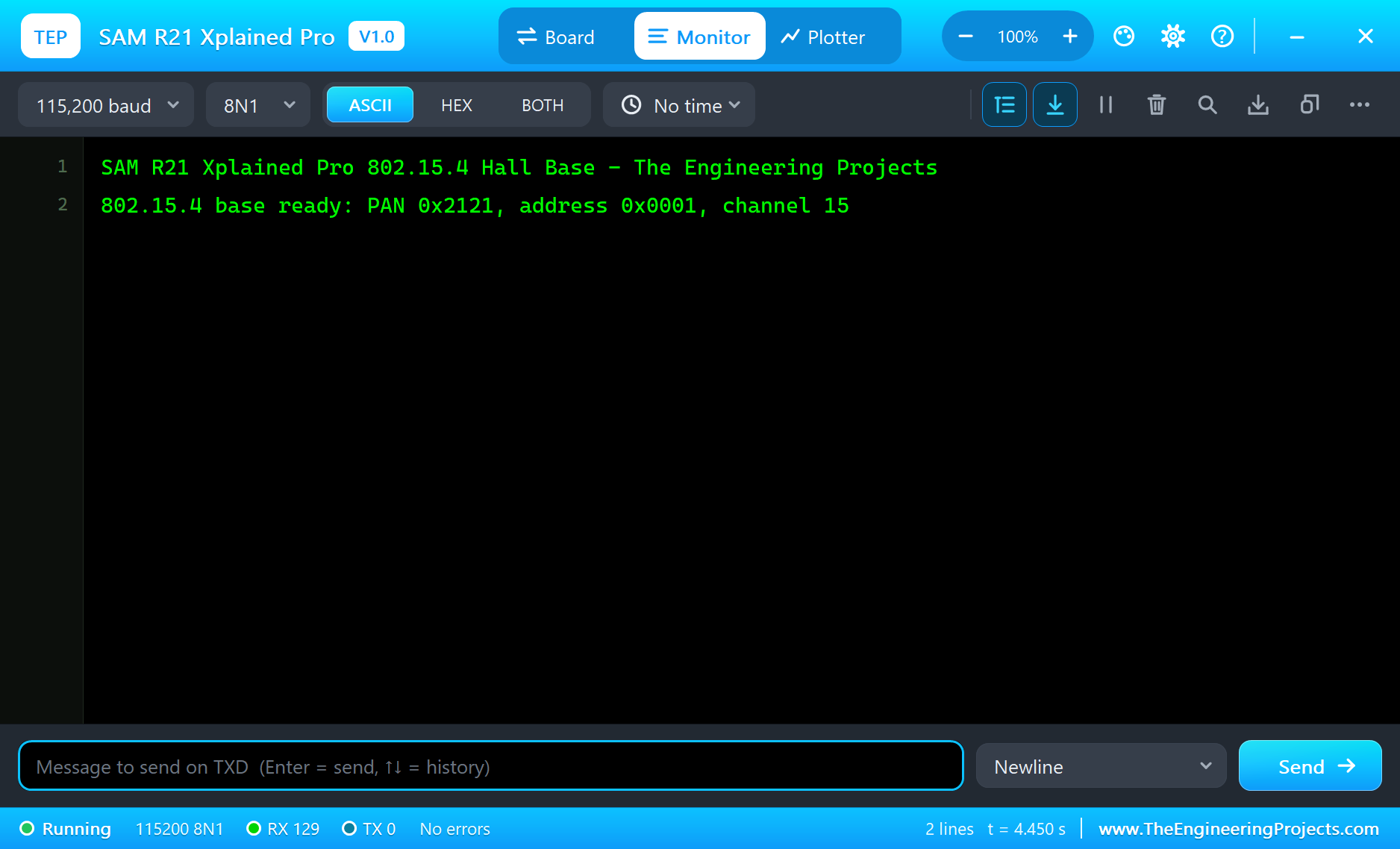
Press Run. Both boards join PAN 0x2121 on channel 15:
SAM R21 Xplained Pro 802.15.4 Hall Node - The Engineering Projects
802.15.4 ready: PAN 0x2121, address 0x0002, channel 15

SAM R21 Xplained Pro 802.15.4 Hall Base - The Engineering Projects
802.15.4 base ready: PAN 0x2121, address 0x0001, channel 15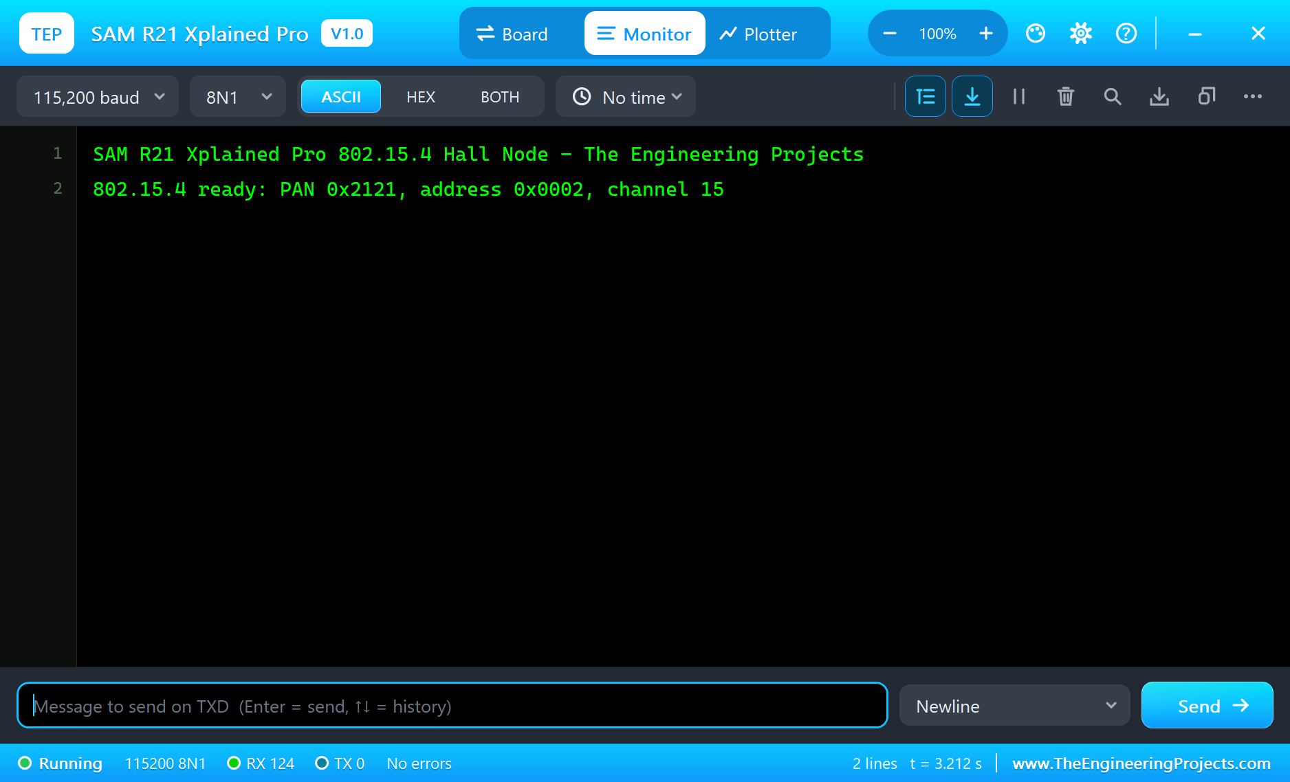
Someone Walks In
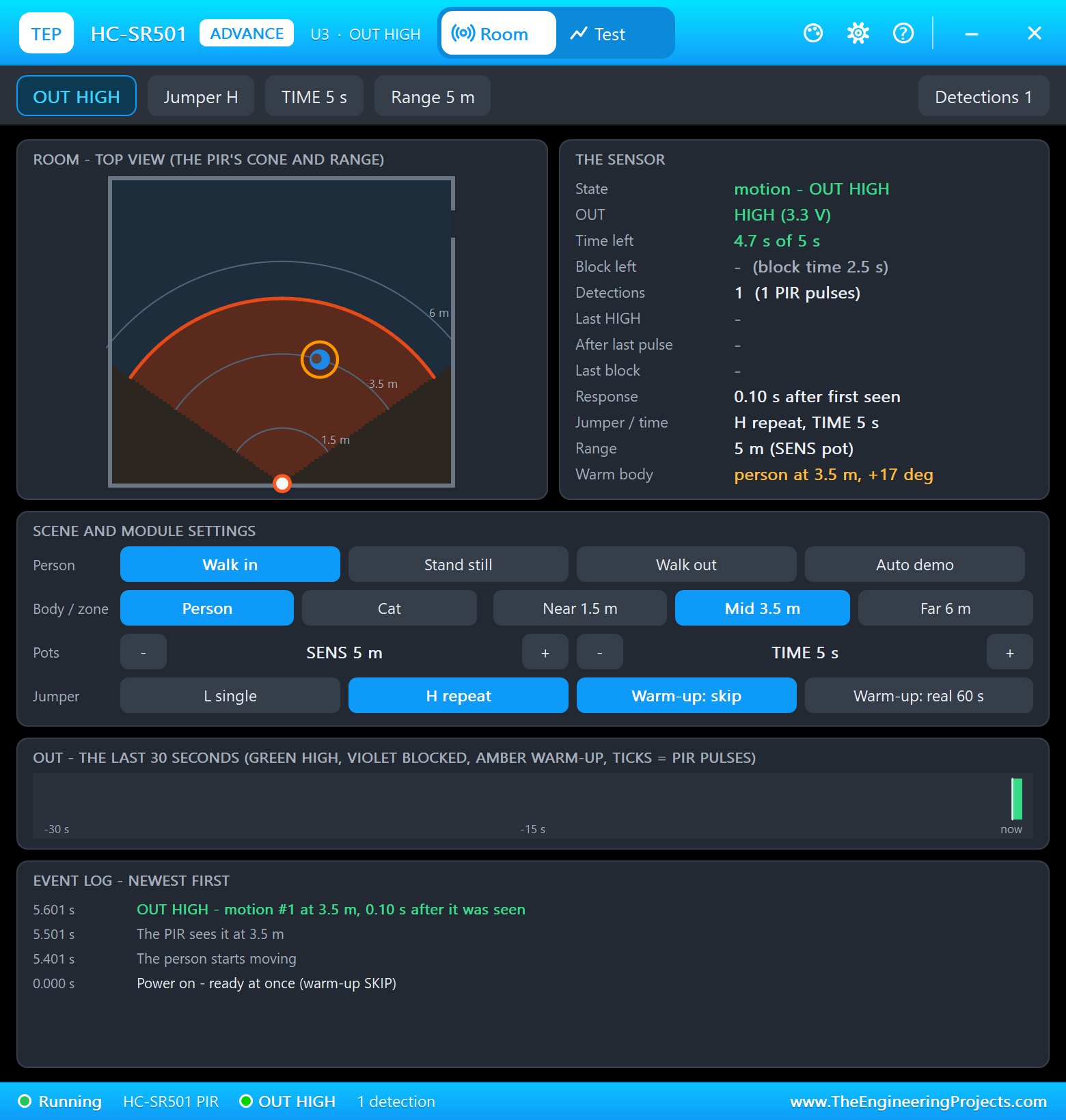
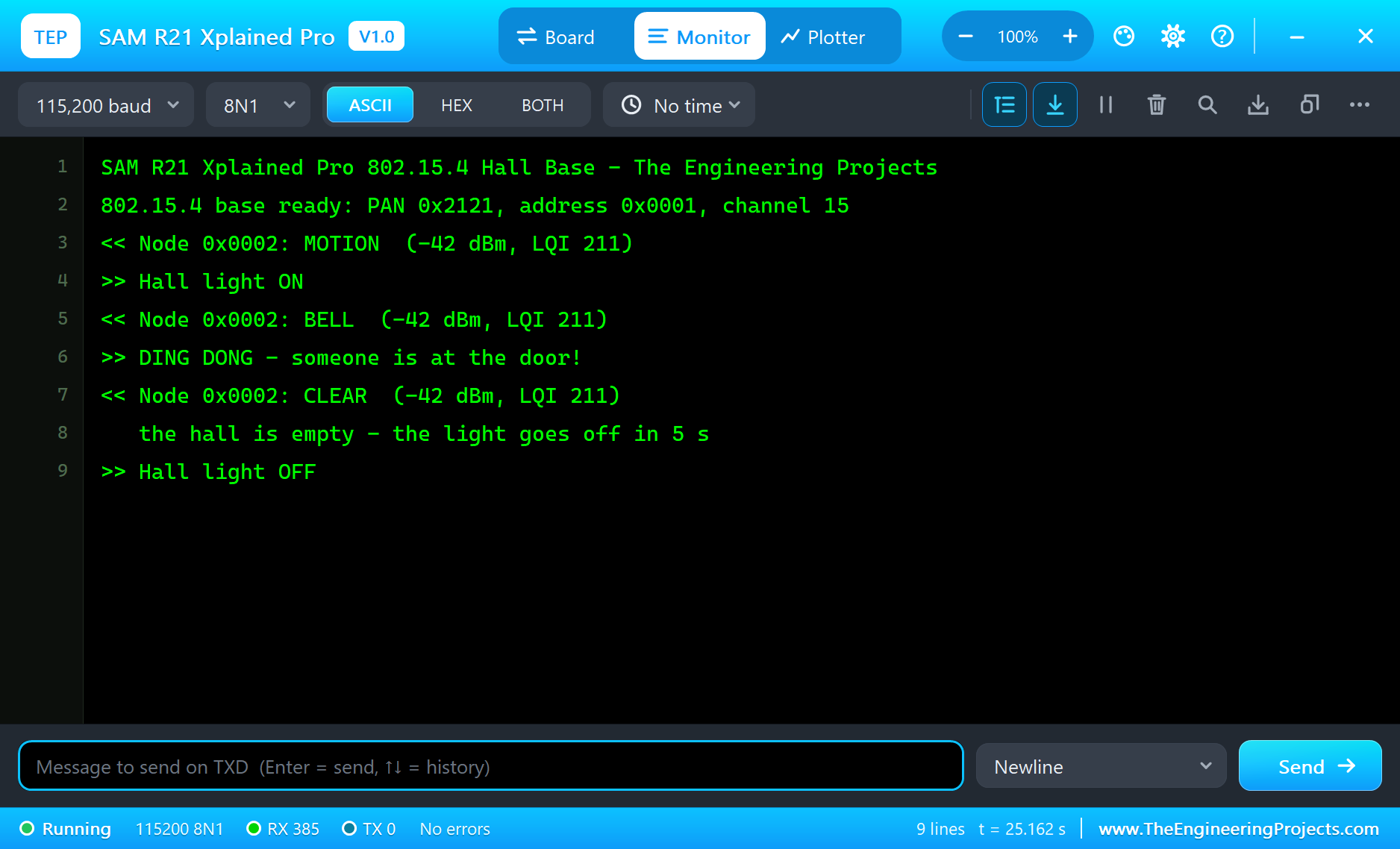
Open the PIR sensor's window and click Walk in. The node sends MOTION and lights LED0, the base confirms it and switches the hall light on:
>> MOTION (frame 1)
<< The base confirmed MOTION  (-42 dBm, LQI 211)

<< Node 0x0002: MOTION  (-42 dBm, LQI 211)
>> Hall light ON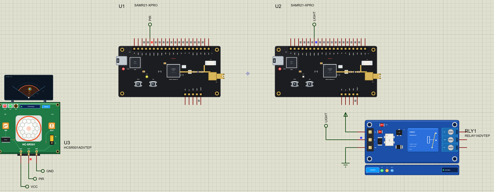
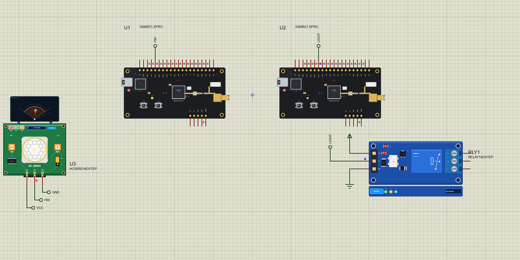
Here is the complete circuit while the simulation runs:
The Doorbell
Click SW0 on U1. The node sends BELL, and the base rings and lights its LED0 for three seconds:
<< Node 0x0002: BELL  (-42 dBm, LQI 211)
>> DING DONG - someone is at the door!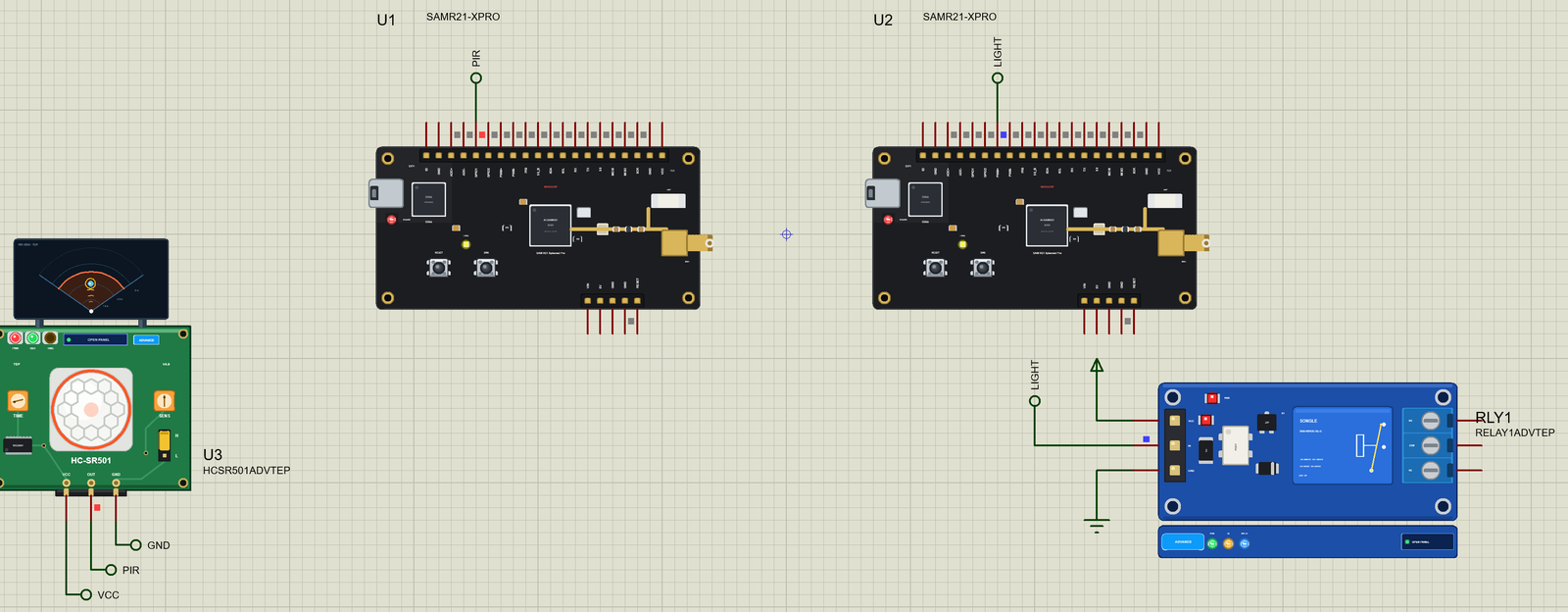
The Hall Is Empty
Click Walk out. The node sends CLEAR and its LED0 goes off; five seconds later the base switches the light off:
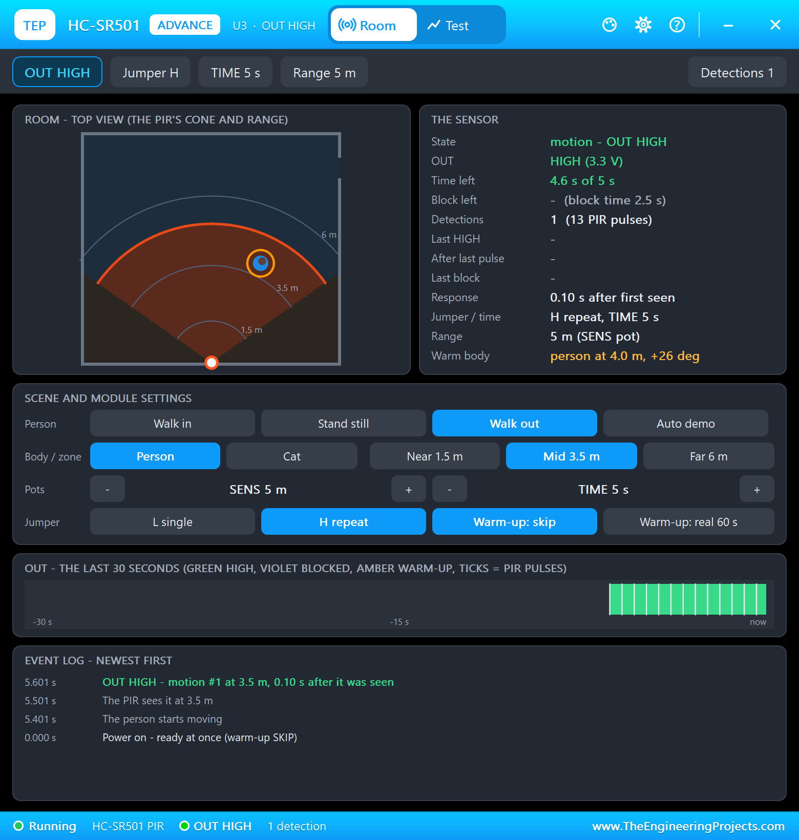
<< Node 0x0002: CLEAR  (-42 dBm, LQI 211)
   the hall is empty - the light goes off in 5 s
>> Hall light OFF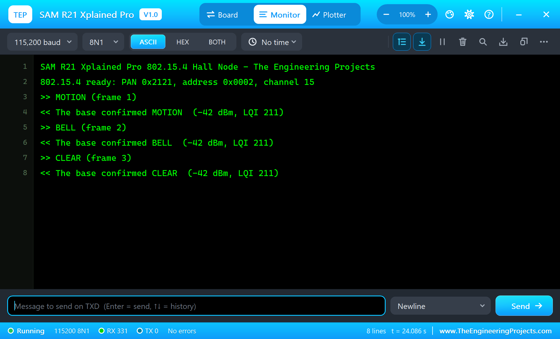
RSSI and LQI
Every frame comes with two numbers. RSSI is the strength of the signal in dBm; at a few metres it is high, around -40 dBm. LQI, the link quality indicator, is a number from 0 to 255 that 802.15.4 radios report for each frame: the higher, the more reliable the link. Networks use it to choose the best route through other nodes.
Battery Life of a Real Node
The node in our demo only talks when something happens: a few frames when someone comes in or rings. A real node would sleep the radio and the processor between events and wake on the PIR's output or the button. The radio needs a few milliamps for a few milliseconds per frame, and the chip sleeps at a few microamps, so a pair of AA cells can last for years. That is the reason building and lighting control use 802.15.4 instead of Wi-Fi.
Try It Yourself
- Change
LIGHT_HOLD_MSto keep the light on longer after the hall is empty. - Send BELL to
RF233_BROADCASTso that every base of the PAN rings. - Add a second node with address 0x0003 at the back door, and let the base print which door it was.
- Move both boards to channel 20 with
RF233.setChannel(20)and see that they still talk.
Ideas to Extend the Network
- Add a temperature sensor to the node and send a reading every minute.
- Put the node to sleep between events to make its battery last for years.
- Let the base forward every event to a PC over its serial port.
- Build a small mesh: a third board that repeats frames between the node and a far base.
Your Own Sketches
Write the sketch in the Arduino IDE with the board Microchip SAM R21 Xplained Pro (TEP Proteus), use Sketch > Export Compiled Binary and set the part's PROGRAM property to the .hex. Give every board of a network the same PAN ID and channel, and a different address.
Moving to Real SAM R21 Xplained Pro Boards
- Install Microchip Studio or MPLAB X with the Advanced Software Framework, or RIOT OS with its samr21-xpro board.
- Use the LwMesh stack (or RIOT's network stack) for the frames: it has a PAN ID, short addresses and channels like RF233.
- Keep the same frame contents, the same confirmations and the same repeats.
- Connect the PIR sensor and the relay module to EXT1 pins 5 and 7 and power them as on the demo sheet.
- Program each board through its EDBG USB and open the virtual COM port at 115200.
The protocol is the part that takes the longest to get right, and it is exactly the part the simulation lets you test first.
Things to Know Before Using a Real SAM R21 Xplained Pro
- The antenna: the board has a chip antenna and an SMA socket; check which one the RF switch selects.
- 3.3 V logic: the extension headers are 3.3 V; use level shifters for 5 V modules.
- Channels: 802.15.4 shares the 2.4 GHz band with Wi-Fi; channels 15, 20, 25 and 26 often sit between Wi-Fi channels.
- Real MAC features: the real radio can send acknowledgements and retries by itself; RF233 in the simulation leaves them to your sketch.
Properties of the SAM R21 Xplained Pro
| Property | What it does |
|---|---|
| PROGRAM | the sketch: a .hex from TEP Boards for Proteus (board "Microchip SAM R21 Xplained Pro") |
| MONITOR, BAUD, AUTOOPEN | the built-in serial monitor: on, its baud rate (115200), open at Run |
Troubleshooting
- The other board hears nothing: both need the same PAN ID and channel, and the frame must go to its address or to
RF233_BROADCAST. - A frame gets lost now and then: confirm every frame and repeat it until the confirmation comes.
- LED0 looks inverted: it lights when the pin is LOW.
- SW0 seems dead: use
INPUT_PULLUPand act on the change to LOW. - A number goes wrong above 32767: int is 16 bits in the simulation - use long.
Limitations of the Simulation
- RF233 is our library, not an 802.15.4 stack: no MAC acknowledgements or retries, no security, beacons or 6LoWPAN.
- EXT3, the other headers and the antenna switch are drawn, not modelled.
- Your sketch gets 8 KB of RAM in the simulation, and int is 16 bits there.
- SAM, Xplained, Microchip and Atmel are names of Microchip Technology and Arduino of Arduino; this library is not made or endorsed by them or by Labcenter.
- Tested in Proteus 8.5 in November 2026 (the demo as shipped, about 25 s of simulation). Proteus 7 is not supported.
So, that was all about the SAM R21 Xplained Pro Library for Proteus. I hope it helps you try your sensor network ideas in a simulation before you buy the boards - the frames, the addresses and the confirmations, all on one sheet. For another board with a network port, see our NUCLEO-H743ZI2 Library for Proteus. If you have any questions, ask in the comments and I will help you out. Till the next tutorial, take care and have fun!