Hi Friends! Hope you’re well today. I welcome you on board. In this post today, I’ll detail the emerging opportunities in stocks trading with innovative ideas.
2020 has unleashed the entire world on the battlefield of uncertainty. You cannot assure how companies and firms will evolve in the coming days. With this pandemic, influencing both personal and professional life, our future is not certain. This uncertainty has affected stock trading and the factors influencing it.
Emerging Opportunities In Stocks Trading With Innovative Ideas
Trading is generally considered a risk profession but this is not the case as per innovation in technology. Now, you can easily trade to make profits even if you have little to no money. There are many online service ...
Hi Friends! Hope you’re well today. I welcome you on board. In this post today, I’ll describe the Introduction to 74LS74.
74LS74A flip-flop IC carries the Schottky TTL circuitry to generate high-speed D-type flip-flops. Every flip-flop in this chip comes with individual inputs, and also complementary Q and Q`(bar) outputs.
Flip-Flops are normally considered as the basic building blocks of modern digital electronics. These flip-flops are used to store the binary data where stored data can be varied by applying the different inputs.
I suggest you buckle up as in this post I’ll walk you through the complete introduction to 74LS74 covering datasheet, pinout, features, and applications.
Let’s get started.
Introduction to 74LS74
74LS74A flip-flop ...
Hello Everyone! Hope you’re well today. Happy to see you around. In this post today, I’ll walk you through the Introduction to CD4035.The CD4035 is a shift register that is mainly used in counters, control circuits, and registers. It contains clocked signal serial chip that is a four-stage register. Synchronous Parallel inputs are provided to each stage and serial inputs are offered to the first stage via JK logic.
I suggest you read this post all the way through as I’ll detail the complete introduction to CD4035 covering datasheet, pinout, features, alternatives, and applications. Let’s jump right in.
Introduction to CD4035
The CD4035 is a shift register that is a 16-pin device and is mainly used in control circuits, counters, and registers.
It is a four-stage register that ...
Hello Pals! We welcome you at The Engineering Projects. We Hope you are fine. We are going to learn about the Benefits of B2B e-commerce.
Despite the rapid growth of the B2B market, especially compared to its B2C counterpart, we’re still seeing a surprisingly low adoption rate of modern e-Commerce solutions on that front. Which is unfortunate for the companies that are still failing to adopt those solutions, as it’s resulted in many of them lagging behind their competitors. On the bright side, this has created a great opportunity for those willing to go the extra mile, as investing in a competent, modern B2B e-Commerce solution can result in numerous benefits, some of which will be visible almost immediately.
...
Hi Mentees! I welcome you on behalf of The Engineering Projects. In this section of this DLD Logic gates series, we are discussing different applications of logic gates. We have discussed DLD Adders and Subtractors in our previous lectures and now it's time to have a look at DLD Multiplexers.
What are Multiplexers?
What are the types of Multiplexers?
What are the two input Multiplexers?
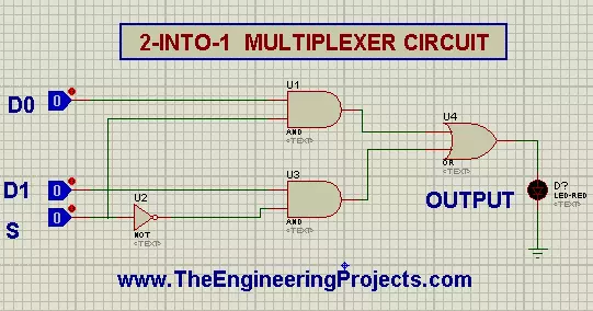
How can we simulate the Circuit of 2 to 2 MUX in Proteus ISIS?
How can we use the 2 to 1 MUX as OR, AND and NOT gates?
What are Multiplexers?
When I heard the word Multiplexer, I thought that as Adder adds numbers, Subtractor subtracts numbers, similarly, the Multiplexer will multiply binary numbers but that's not the case. Multiplexer is defined as:
A Multiplexer(also called MUX or ...
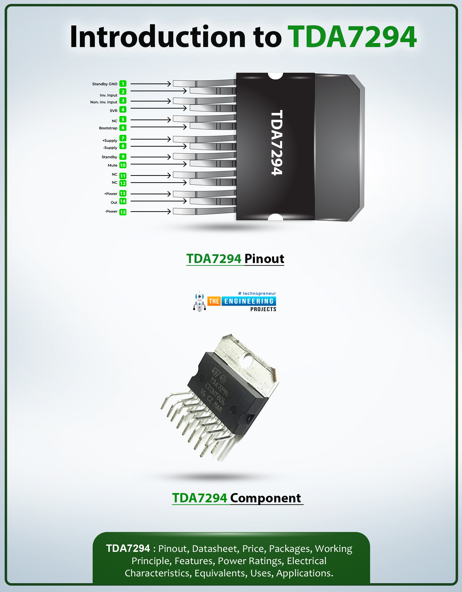
Hi Guys! Hope you’re well today. I welcome you on board. In this post today, I’ll walk you through the Introduction to TDA7294.
TDA7294 is a monolithic class AB power-based audio amplifier that comes with a DMOS output stage. It is primarily used for the amplification of audio signals in Hi-Fi field applications containing self-powered loudspeakers. The fault protection circuitry used in this device protects against short circuits.
I suggest you read this post all the way through, as I’ll detail the complete introduction to TDA7294 covering datasheet, pinout, features, and applications.
Let’s get started.
Introduction to TDA7294
TDA7294 is a monolithic class AB power-based audio amplifier that comes with a DMOS output stage.
This device comes with a wide voltage supply ra ...
Hi Folks! I welcome you on board. Happy to see you around. In this post today, I’ll detail the Introduction to TDA2030. This device incorporates a TDA2030 audio amplifier chip that produces 18 W output power with low harmonic distortion.I suggest you read this post till the end as I’ll walk you through the complete Introduction to TDA2030 covering pinout, datasheet, features, and applications.
Let’s get started.
Introduction to TDA2030
TDA2030 is a monolithic integrated circuit that comes in a Pentawatt package, mainly used as a low-frequency class AB amplifier.
The audio amplifier is a basic circuitry used to amplify the audio signal obtained through a device like a microphone.
Audio amplifiers are widely used in scores of app ...
Hey pals! Welcome to the Engineering Project. We hope you are have a good day. First, we need to understand what automation is, and what its objectives are.
Automation is simply the integration of technology to process or run its functions with minimal human intervention or assistance. Its objectives are to improve efficiency, speed and precision of hard or long tasks that are usually performed by humans.
For example, accounting and producing and delivery of products, which were formerly and majorly done by humans. But, in the world of modernity and technology, automation was invented to minimize costs and risks while maximizing profits.
Overall, an open line of communication and good management skills are both critical during the implementati ...
Hi Friends! Welcome to The Engineering Projects. At the present time, it is an important to upgrade the technical skills. As we approach a more digital era, the use of the internet has become part of our day-to-day activities. When it comes to looking up for something online, we always go to our chosen and trusted websites for information. Our trusted website, of course, is pleasing to the eyes, with all the functions and settings working perfectly.
Although as a browser, we would sometimes not bother to give a second look at the web design or how it was developed. But if by any chance, your mind seeks to know more, to have in-depth knowledge about websites in general, this article seeks to explain the difference between web design and web develop ...
Hello Guys! I welcome you on board. Happy to see you around. In this post today, I’ll walk you through the Introduction to Arduino MKR GSM 1400.
The Arduino MKR GSM 1400 is a microcontroller board that is based on the SAMD21 microcontroller. This device connects with a cellular network for developing communication. This GSM board is a one-stop solution for developing your sensor network or you can use it as a device sending a text message about the occurring of certain events remotely.
A module from u-blox, the SARA-U201 (which is a power chipset that activates using multiple cellular range bands) is responsible for GSM / 3G connectivity inside the device.
I recommend you read this post till the end as I’ll detail the complete Introduction to A ...