Hello friends! Today we will build an adjustable DC supply using an LM317 voltage regulator in Proteus. We will calculate the output-setting resistors, check the available voltage range, and see why load current and temperature matter as much as the potentiometer setting. Our earlier 5 V supply using a 7805 provides a fixed output. The LM317 uses an external resistor network to set its output, making it useful when a project needs a different low-voltage supply. It does not, however, provide every voltage from zero to the input voltage. The original motor demonstration, images, video and download remain in this tutorial. We will explain the historical readings while correcting its missing LED current limiter, capacitor choices and assumptions about the maximum output. Start with a resistiv ...
Hello friends! Today we will control a hobby servo from a 555 timer in Proteus ISIS. We will generate a repeating position-command pulse, measure its width, and see how changing that width changes the simulated shaft position. This project is a useful way to connect timer theory with motion control. The servo has its own internal motor driver and feedback system; our 555 supplies a command signal, not the motor's operating current. The command pulse must have suitable voltage levels, timing and repetition. The original diagrams and download are preserved below. We will correct two important points from the older explanation: a servo does not universally rotate from −180 to +180 degrees, and the 555's threshold is a fraction of its supply rather than a fixed 5 V value. Figure: Historical se ...
Hello friends! Today we will study LED dimming using a 555 timer in Proteus ISIS. In our earlier single and double LED flasher and multiple LED flasher , the visible effect was a repeated change between on and off. Here we want to understand how a circuit changes apparent brightness. We will first examine the original fading demonstration, then build a controlled pulse-width-modulation example. PWM lets us change the fraction of time an LED conducts while keeping its on-state current limited. The important measurements are pulse width, repetition period and LED current. The original screenshots and download are retained. Their off, dim and bright images show the intended visual effect, but a still image cannot establish the electrical waveform. We will use the oscilloscope to distinguish a ...
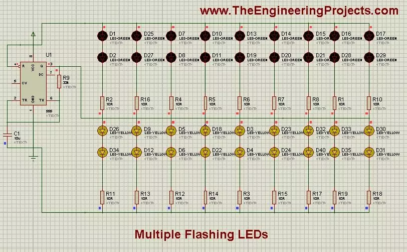
Hello friends! Today we will extend our single and double LED flasher into a multiple-LED display using a 555 timer in Proteus ISIS. Two groups of LEDs will alternate, making a repeating pattern without a microcontroller. Adding LEDs looks simple in a simulator, but it changes the electrical load. We will therefore calculate the current in each branch, add the branch currents to find the load on the timer, and use a standard astable circuit whose timing is easier to predict. The original decorative arrangement and download remain below. We will keep its visual idea while explaining the changes needed for a sensible physical build. In particular, do not copy the original 10 Ω LED resistors without evaluating the supply voltage and current. Figure: Multiple LED alternating pattern in Proteus ...
Hello friends! Today we will read analog voltages with an Arduino Uno and display both the ADC readings and calculated voltages on a 20 × 4 LCD. We will build the circuit in Proteus, connect the display, write the sketch and work through the conversion from a digital count to volts. Libraries LCD Simulation Libraries Latest library: LCD Library for Proteus V3.0 (October 2026): LCD 16x2, LCD 20x4 and both I2C LCDs in one library, with our own HD44780 model and an Arduino demo One LCD only? LCD 16x2 · LCD 20x4 · I2C LCD 16x2 · I2C LCD 20x4 Helping Tools Serial Monitor Advance : a serial terminal window for the UART of your board Serial Monitor Expert : the serial monitor with extra debugging tools The central idea is simple: analogRead() returns a number that represents the input relative to ...
Hello friends! Today we will build an LED flashing circuit using a 555 timer in Proteus ISIS. We will start with one LED, calculate its on and off times, and then connect two LEDs so they alternate. No microcontroller program is needed because the timer and its resistor-capacitor network generate the repeating signal. This is a useful first electronics project because you can see the result while also measuring the signal that produces it. We will connect the circuit step by step, examine the timing capacitor voltage, and compare the calculated period with the waveform in the simulator. The original diagrams and downloads remain in this tutorial. Some historical connections differ from the recommended arrangement described below, so we will identify those differences explicitly. If you are ...
Hello friends! This page organizes our Arduino projects into a practical learning path. We will begin with board setup and a first sketch, then move through displays, sensors, communication and combined applications. The aim is to help you choose the next useful exercise instead of searching through an unrelated collection of links. Work through the projects actively. Read the circuit, predict the result, run a small example and explain any difference you observe. You can also explore our Arduino projects for beginners and the corresponding PIC microcontroller project guide when comparing learning paths. The collection includes historical boards, software and simulation packages. Keep each tutorial's exact hardware and version requirements in mind. An example written for a classic Uno or a ...
Hello friends! This page brings together our PIC microcontroller projects in a learning sequence. We will start with the controller, programming tools and a basic LED, then move through displays, inputs, analog measurements and motor-control exercises. Each linked tutorial gives you a practical next step instead of leaving you with an unrelated list of projects. If you are beginning with PIC devices, work through one small circuit at a time. Read the explanation, identify the important connections, build or simulate the example, and record what you observed. Understanding why a simple project works is more useful than collecting several HEX files you cannot adapt. Many tutorials in this collection were originally written around older PIC devices and development tools. Their core ideas rema ...
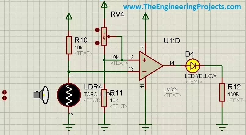
Hello friends! Today we will use an LDR sensor in Proteus to make a light-controlled LED circuit. We will begin with the photoresistor itself, convert its changing resistance into a voltage, and then compare that voltage with a reference to decide when the LED should illuminate. The original project demonstrates both a numeric light control and an animated torch control in Proteus. We will retain those illustrations and the project download while explaining what the circuit actually measures. A simulator control value is not automatically a measured voltage, and a photoresistor does not directly produce a calibrated lux reading. If you are new to the schematic editor, our Proteus ISIS and ARES tutorial collection covers the basic workflow. Here we will concentrate on the sensor, threshold ...
Hello friends! Today we will interface a seven-segment display with an Arduino Uno in Proteus. We will build a single-digit counter, load the Arduino program into the simulated board, and check that the display counts from zero to nine before returning to zero. This tutorial uses our Arduino Library for Seven Segment Display . That is a sketch library, while the Arduino Library for Proteus supplies a board model for the simulator. They belong to different applications and cannot replace one another. We will retain the original circuit images and downloadable project, but correct the counting logic and explain the electrical details that a simple simulation can hide. The objective is to understand how a requested digit becomes seven output signals, not merely to watch an animation. Figure: ...