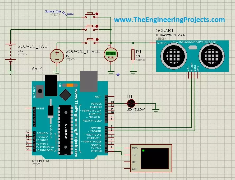
Hello friends! In the Ultrasonic Sensor Library for Proteus tutorial, we installed the model and printed distance readings with an Arduino Uno. Now we will use that same interface in three practical simulations: selecting test distances with buttons, producing a proximity indication, and stepping through test conditions with a switch. Libraries Libraries used in this tutorial Ultrasonic Sensor Library for Proteus: V1.0 (2015, used in this tutorial) · latest version: V2.0 (October 2026) Helping Tools Serial Monitor Advance : a serial terminal window for the UART of your board Serial Monitor Expert : the serial monitor with extra debugging tools LCD Library for Proteus V3.0 : 16x2, 20x4 and I2C LCDs to show your readings The central idea is simple. Our legacy sensor model has an additional a ...
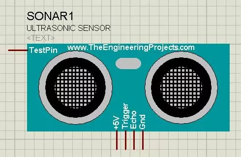
Hello friends! Today I will show you how to install our Ultrasonic Sensor Library for Proteus and use it with an Arduino Uno. We will begin with the library files, place the sensor on a schematic, connect its simulation input and then read the distance through the Virtual Terminal. This is the original HC-SR04-style library introduced in this tutorial. Updates Ultrasonic Sensor Library for Proteus Latest version: Ultrasonic Sensor Library for Proteus V2.0 (October 2026): HC-SR04 with real TRIG and ECHO timing, Simple and Advance devices, test tools and an Arduino demo Earlier versions: V1.0 (2015, this tutorial) Other distance and motion sensors: JSN-SR04T · Sharp IR · TF-Luna LiDAR · VL53L0X · PIR HC-SR501 · RCWL-0516 · IR Obstacle FC-51 Helping Tools Serial Monitor Advance : a serial ter ...
Hello friends! In our previous tutorial, we installed the Arduino LilyPad library for Proteus . Now we will use that board in a small circuit with three LEDs and a pushbutton, then extend the same project to an analog level indicator. Libraries Libraries used in this tutorial Arduino Lilypad Library for Proteus: V1.0 (2014, used in this tutorial) Newer Arduino boards: UNO · Mega 2560 · Mega 1280 · Nano · Pro Mini · Mini (V4.0) Helping Tools Serial Monitor Advance : a serial terminal window for the UART of your board Serial Monitor Expert : the serial monitor with extra debugging tools LCD Library for Proteus V3.0 : 16x2, 20x4 and I2C LCDs to show your readings The basic behaviour is easy to observe: when the button is released, all three LEDs are on; when it is pressed, they turn off. This ...
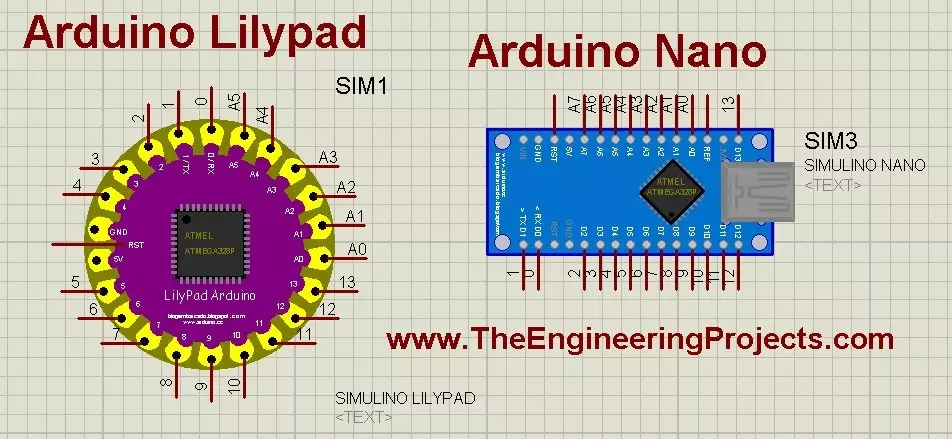
Hello friends! Today, we will install the Arduino LilyPad library for Proteus and prepare a small simulation to check the installation. This article continues our earlier Arduino library tutorial , with particular attention to the LilyPad and Nano parts included in this older library package. Updates Arduino Lilypad Library for Proteus Latest version: V1.0 (December 2014, this tutorial) Other Arduino boards: UNO · Mega 2560 · Mega 1280 · Nano · Pro Mini · Mini (V4.0) All six V4.0 boards in one package: Arduino Library for Proteus V4.0 Helping Tools Serial Monitor Advance : a serial terminal window for the UART of your board Serial Monitor Expert : the serial monitor with extra debugging tools LCD Library for Proteus V3.0 : 16x2, 20x4 and I2C LCDs to show your readings We will start by iden ...
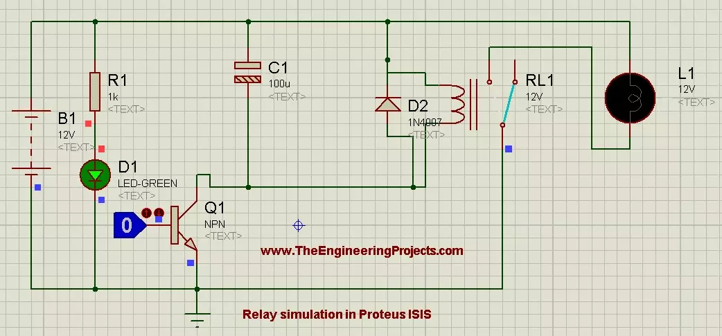
Hello friends! Today, we will learn how to control a relay in Proteus ISIS. We will begin with a simple circuit that energizes a relay coil and switches a lamp, then add a transistor so a low-voltage logic signal can control the coil. This follows naturally from our tutorials on DC motor control , stepper motor control and servo motor control . A relay is useful for switching a load on or off, but it is not the best choice for every motor-control task, particularly rapid speed control. We will keep the demonstration at low DC voltage and use a lamp as the load. The original screenshots remain below, while the connection tables explain the base resistor, protection diode and supply relationships that you should include when building a complete driver circuit. Figure: Relay control demonstra ...
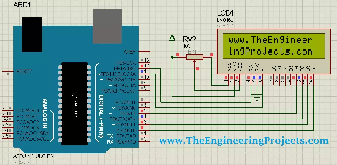
Hello friends! Today, we will design a circuit containing an Arduino UNO and a 16 × 2 character LCD in Proteus ISIS. We will connect the display, write a small Arduino sketch, compile it and load the resulting program into the simulated UNO. Our first result will be the website name displayed across two rows. Libraries LCD Simulation Libraries Latest library: LCD Library for Proteus V3.0 (October 2026): LCD 16x2, LCD 20x4 and both I2C LCDs in one library, with our own HD44780 model and an Arduino demo One LCD only? LCD 16x2 · LCD 20x4 · I2C LCD 16x2 · I2C LCD 20x4 Helping Tools Serial Monitor Advance : a serial terminal window for the UART of your board Serial Monitor Expert : the serial monitor with extra debugging tools This is a useful beginner project because the visible result is simp ...
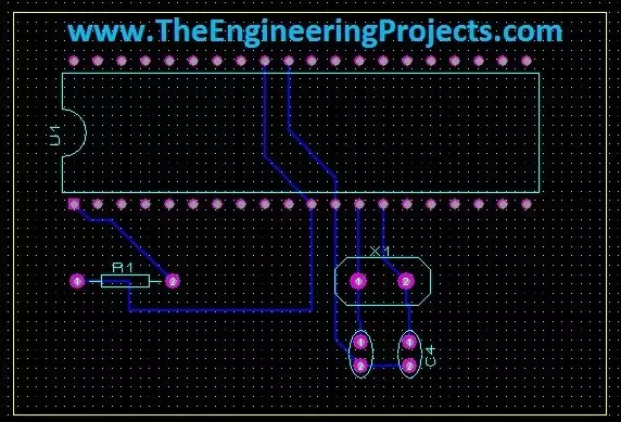
Hello friends! Today we will move from a circuit diagram to a printed circuit board using Proteus ARES. We will use a small PIC16F877A circuit so that placement, connectivity, and routing remain easy to follow. The same sequence of decisions applies when you later design a larger board. Proteus schematic capture describes which component pins belong to each electrical net. PCB layout turns those connections into physical pads and copper tracks. A completed route is useful only when the footprint, pin mapping, power connections, and manufacturing rules are also correct. We will follow the original illustrated workflow: prepare the schematic, transfer its connectivity, define the board edge, place components, and route the board. We will then add the checks needed before sending a design for ...
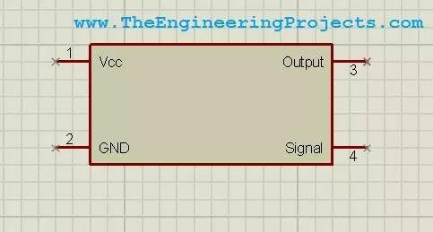
Hello friends! Today we will design a custom component in Proteus ISIS. This is useful when you need to document a circuit but cannot find the exact module, connector, or device in your installed library. We will draw a simple four-pin symbol, define its connections, and save it so that it can be placed like other library parts. The original purpose of this tutorial is schematic presentation, and we will keep that approach. A clear custom symbol helps another person understand how your project is connected. We will also discuss the extra information required before the same part can be used for PCB layout or electrical simulation. Our example is a fictional device named Test Device with VCC, GND, OUTPUT, and SIGNAL connections. These names let us practise the workflow without claiming to r ...
Hello friends! Today we will control a servo motor with the PIC16F877A and observe its movement in Proteus ISIS. We will begin with the three servo connections, understand the command waveform, and then write a small program that selects positions using two pushbuttons. In the previous tutorials, we explored DC motor direction control and stepper motor sequencing . A positional hobby servo is different because the motor, gearbox, position sensor, and controller are already assembled together. Our PIC requests a position rather than switching the motor windings itself. We will keep the original PIC and button arrangement, but use a repeated control pulse with a sensible frame period. Along the way, we will separate what the simulated angle display tells us from what a physical servo must be ...
Hello friends! In the previous tutorial, we controlled the direction of a DC motor in Proteus . Now we will work with a stepper motor, where rotation depends on applying an ordered sequence to the windings. We will begin with the original six-wire simulation, inspect the sequence manually, and then explain how a microcontroller and driver can generate it. The original screenshots use Logic State sources to make individual winding states visible. They are useful for understanding the sequence, but they are not a physical driver circuit. We will preserve the images and add the missing distinction between simulated logic sources, microcontroller outputs, and the winding-current path. By the end, you should understand unipolar and bipolar wiring, wave drive and half stepping, direction reversa ...