Hello friends! In this tutorial, we will design a DC motor control demonstration in Proteus ISIS and then connect its control logic to a PIC16F877A. We will begin by observing how voltage polarity changes the direction of a simulated motor, then explain the driver stage needed between a microcontroller and a physical motor. The original article used Logic State sources and a simplified direct connection to illustrate direction changes. We will preserve those screenshots, but label their purpose clearly. Logic sources and PIC output pins are not substitutes for a motor power driver. The updated practical interface uses an L293D bridge example, with separate logic and motor supplies. We will also correct the relationship between the original schematic and code, add explicit stopping behavior ...
Hello friends! In this tutorial, we will learn how to use the oscilloscope in Proteus ISIS to inspect waveforms, measure voltage and timing, and compare signals at different points in a circuit. In the previous article, we used Virtual Terminal to read serial characters. The oscilloscope lets us examine the electrical waveform behind a signal instead of only its decoded text. We will retain the original inverter demonstration and its screenshots, but begin with the measurement principles needed to interpret them correctly. A waveform that looks smooth is not automatically a verified pure sine wave, and two traces connected to opposite sides of a load do not automatically display the voltage difference across that load. By the end, you should be able to choose a suitable volts-per-division ...
Hello friends! In this tutorial, we will learn how to use Virtual Terminal in Proteus ISIS to inspect serial data and send simple commands to a simulated circuit. It is particularly useful when working with microcontrollers, GSM modules, GPS receivers, and other devices whose behavior can be understood through a serial interface. We will begin with the simplest arrangement: a simulated microcontroller communicating directly with Virtual Terminal. Then we will return to the original article's COMPIM example, which connects a simulation to a real computer serial port. Keeping those two arrangements separate will help you choose the correct components and avoid unnecessary COM-port problems. The aim is to make serial communication visible before building a larger application around it. We wil ...
Hello friends! In this tutorial, we will explore the components and instruments available in Proteus ISIS and learn how to choose the right item for a circuit. Finding a familiar part name is only the beginning. We also need to know whether it has a simulation model, which properties must be configured, and whether the item belongs to the schematic, the measurement setup, or a later PCB design. This article continues our practical Proteus series after designing an LCD circuit with a PIC microcontroller . We will cover ordinary components, displays, motors, serial tools, and shift registers, then connect each topic to the more detailed tutorials already available in the series. My aim is to help you build a sensible test circuit instead of placing unfamiliar parts and hoping that the simula ...
Hello friends! In this tutorial, we will design a circuit that connects a 16×2 character LCD to a PIC18F452 microcontroller in Proteus ISIS. We will select the components, wire the display, write a small program in mikroC PRO for PIC, load its HEX file into the simulated microcontroller, and display text on both rows. This is a useful first microcontroller simulation because it combines several skills in one manageable circuit: choosing the correct device, matching software pins to schematic wires, setting the clock frequency, and checking the result. If you are new to the workspace, start with our Proteus ISIS and ARES guide , then return here for the practical example. We will preserve the original PORTD connections and two-line website message. The explanation now also covers the LCD co ...
Hello friends! In this guide, we will learn how to use Proteus ISIS and ARES, starting with a simple circuit and gradually moving toward microcontroller simulations and PCB design. I have kept the original tutorial collection so that you can follow a lesson in detail whenever you reach that stage. Our goal is to understand the complete development process. We will draw a circuit, calculate what it should do, simulate its behavior, examine signals with instruments and then prepare a physical board layout. Each stage answers a different question, so a successful simulation is one step in the process rather than the final proof of a finished product. If you are new to Proteus, follow the sections in order. If you already use it, choose the topic you need from the linked lessons. Some screensh ...
Hello friends, I hope you are doing well. In this tutorial, we will design the timing logic for a modified sine-wave inverter and study the original CD4047B and CD4017B approach. We will also develop an equivalent microcontroller timing example so you can see exactly how the positive, zero and negative intervals are produced. This article follows our tutorials on the basics of inverter topologies , the major inverter components and the pure sine-wave inverter . A modified waveform is simpler than filtered SPWM, but its harmonic content limits the loads that should use it. Figure: The comparison shows sinusoidal and stepped waveforms over a labeled 20 ms cycle. What Is a Modified Sine Wave? A modified sine wave is a stepped bipolar waveform. During each cycle, the inverter applies a positiv ...
Hello friends, I hope you are doing well. In the previous tutorials, we studied the basics of inverter topologies and the major components of an inverter . We will now connect those ideas and study how an AVR controller can create a sine reference for a pulse-width-modulated inverter. This tutorial explains the signal chain, frequency calculations, H-bridge states, LC filter and transformer. The AVR code is an educational SPWM reference generator for an ATmega16 running at 8 MHz. It is useful for simulation and low-energy waveform testing, but it must not be connected directly to power MOSFET gates. A physical inverter needs proper high-side and low-side gate drivers, hardware dead time, current limiting, voltage feedback, thermal protection and a safe PCB layout. The original project pack ...
Hello friends, I hope you are doing well. In the previous tutorial, we studied the working principle of a relay . Today, we will connect a 12 V relay to a PIC18F4550 microcontroller through a ULN2003A driver. A relay coil needs more voltage and current than a microcontroller pin should provide. It is also an inductive load, so it produces a voltage transient when switched off. The ULN2003A solves these interface problems by providing seven low-side Darlington drivers and seven internal clamp diodes in one package. The key point is that the ULN2003A does not convert a 5 V logic signal into a 12 V output. The 12 V energy comes from a separate 12 V supply. A logic high merely turns on one internal driver, which connects the low side of the relay coil to ground. We will examine that current pa ...
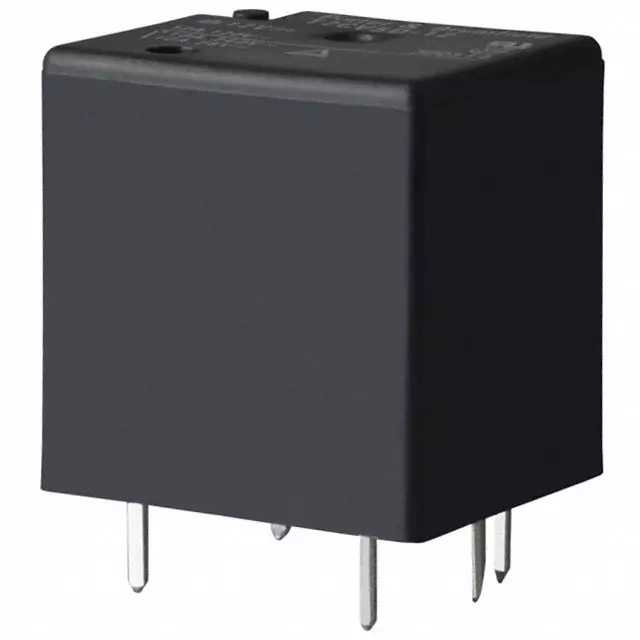
Hello everyone! I hope you are doing well. In this tutorial, we will study the relay from its basic construction to practical selection and control. A relay allows one electrical circuit to operate contacts in another circuit. This makes it useful when a low-power controller must switch a different voltage, a larger load or an electrically isolated circuit. Libraries Relay Simulation Libraries Latest library: Relay Module Library for Proteus V1.0 (October 2026) Other motor drivers: L298 · L9110S · TB6612FNG · BTS7960 · A4988 / DRV8825 · 28BYJ-48 + ULN2003 · PCA9685 Servo · 30A Brushless ESC · TB6600 Stepper Driver · 60A Brushed ESC · DRV2605L Haptic Driver · ZS-X11H BLDC Driver · SimpleFOC Mini Driver · AC Dimmer Module · TMC2209 Stepper Driver · DRV8833 Motor Driver · L293D Motor Shield H ...