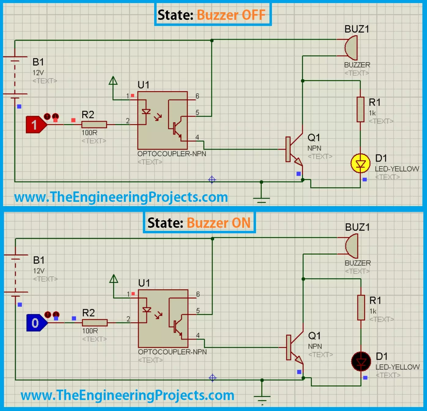
Hello friends! Today we will design and examine a buzzer circuit in Proteus ISIS. We will use a logic input, an optocoupler and a transistor to control a powered buzzer, then look at the changes needed before using the idea in hardware. A buzzer is useful for indicating a timer event, a button press or a fault. The first design decision is whether the selected sounder contains its own oscillator or requires an alternating drive signal. Applying DC works for an active buzzer, but does not produce a continuous tone from every passive transducer. The original simulation images remain in this tutorial. We will explain their active-low behavior while correcting several details that a simulation alone can hide, including LED current, transistor bias and optocoupler pin mapping. Figure: Historica ...
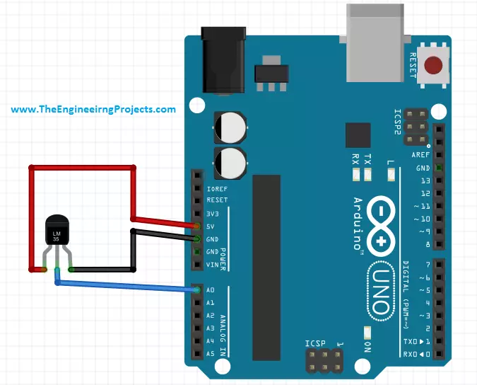
Hello friends! Today we will connect an LM35 temperature sensor to an Arduino Uno and reproduce the measurement in Proteus ISIS. We will start with the sensor's analog output, convert that voltage into temperature, and display Celsius and Fahrenheit readings on a serial terminal. Libraries Libraries used in this tutorial Arduino Library for Proteus: V2.0 (2021, used in this tutorial) · latest version: V4.0 (October 2026) Helping Tools Serial Monitor Advance : a serial terminal window for the UART of your board Serial Monitor Expert : the serial monitor with extra debugging tools LCD Library for Proteus V3.0 : 16x2, 20x4 and I2C LCDs to show your readings The circuit is small, but it teaches several important measurement concepts: ADC resolution, reference voltage, sensor accuracy and the d ...
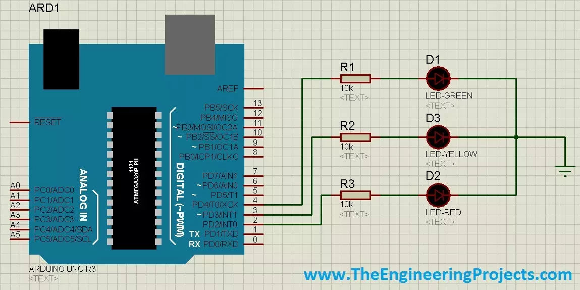
Hello friends! Today we will build a traffic-signal demonstration with Arduino using red, yellow and green LEDs. We will connect the three indicators, define their sequence and write a program that changes states using elapsed time. The same idea can be explored on a breadboard or in a suitable Proteus Arduino simulation. This is an educational model of one signal head. It teaches output control and timed state transitions; it is not a controller for a public road or a complete intersection. Real installations require coordinated phases, fault handling and jurisdiction-specific timing that cannot be established by a three-LED sketch. The original tutorial used long delays and changed directly from green to red before showing yellow. In this revision, we will use a clearly defined red, gree ...
Hello friends! Today we will study a pure sine wave inverter simulation in Proteus, following the signal path from a DC source through the controller, bridge, filter and transformer. The original project uses a PIC16F877A and illustrates a nominal 12 V DC to 220 V AC conversion. We will keep its diagrams while explaining the assumptions needed to interpret them correctly. The first point to understand is that waveform quality and efficiency are different properties. A smooth sinusoidal output does not imply zero losses, and a highly efficient converter does not automatically have low distortion. We need separate measurements for output voltage, frequency, harmonic content and power conversion efficiency. This tutorial explains the historical simulation and how to evaluate such a model. The ...
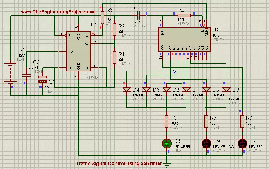
Hello friends! Today, we will build a traffic-signal demonstration using a 555 timer and a CD4017 counter in Proteus ISIS. The timer supplies a repeating clock, the counter advances through ten states, and a few diodes combine those states into red, yellow and green indications. This is a useful introduction to sequencing without a microcontroller. We will keep the original project's teaching flow, but make the timing and output connections more precise. In particular, the CD4017 is a decade counter with decoded outputs, not a serial-data shift register. Its clock input advances a sequence; it does not receive a stream of data bits describing the lamp colors. Our goal is a small educational display. We will calculate the state duration, explain the overlap between red and yellow, and ident ...
Hello friends! Today, we will study relay control using a 555 timer in Proteus ISIS. A relay allows a small control circuit to operate a separate load circuit, and a timer adds a useful extra function: keeping that load on for a selected interval. We will work with a low-voltage DC motor so that the control sequence is easy to observe. Before connecting the components, we need to distinguish manual switching from timed switching. The original project contains a button in the relay-coil path, but that arrangement does not by itself create a timed output. We will first read the original drawing, then develop a monostable circuit whose behavior can be calculated. By the end, you should understand the relay contacts, the transistor interface, the protection diode and the relationship between t ...
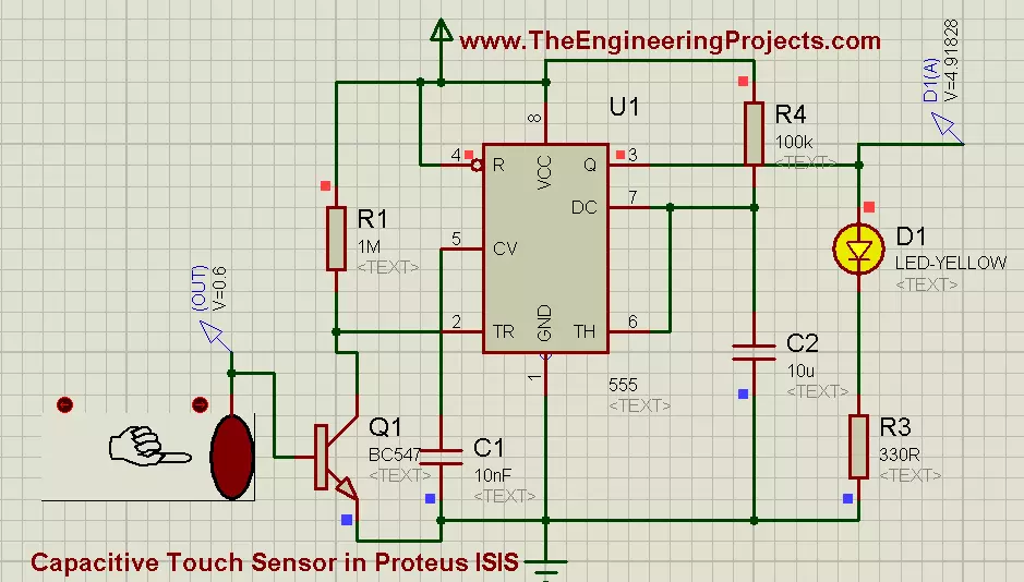
Hello friends! Today we will explore a capacitive-touch demonstration in Proteus and use its output to trigger a 555 timer. The timer will drive an LED, allowing us to follow the signal from the interactive sensor model through a transistor interface to a visible response. We will also separate the simulated touch control from the physics of a real electrode. A real capacitive sensor measures a change in capacitance; a finger does not simply generate a universal 0.6 V signal. The model's output is a convenient representation of detection behavior. The original circuit, images, video and download remain below. We will correct the 555 threshold explanation, add a base-current limiter to the transistor interface, and explain why a timed output can remain active after the touch input changes. ...
Hello friends! Today we will build a single-digit counter using a 555 timer, a CD4026 and a seven-segment display in Proteus ISIS. The timer supplies clock pulses, the counter advances from zero to nine, and its decoder lights the segments needed for each digit. We will also examine three different controls: blanking the display, pausing the count and resetting to zero. They can look similar in a screenshot, but they change different parts of the circuit. Understanding that distinction is useful when you later build event counters or time displays. The original diagrams and download are retained below. We will improve their explanation and add the missing hardware considerations, particularly current-limiting resistors for the display and defined levels on every control input. Figure: Seve ...
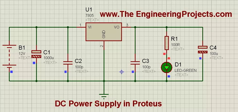
Hello friends! Today we will design a regulated 5 V DC supply in Proteus using a 7805 regulator. We will connect the input, bypass capacitors, indicator and load, then calculate the current and heat so that the simulation becomes a useful starting point for hardware. A regulated supply is often the first circuit a project needs, but the required voltage depends on the actual components. Some circuits use 5 V, others 3.3 V or different rails. Batteries also come in many voltages; the original article's statements that all batteries are 12 V and all electronics operate at 5 V were incorrect. For this exercise, we will deliberately choose a suitable 12 V DC source and a modest 5 V load. The original diagrams and download remain below, with corrections to capacitor values and LED current limit ...
Hello friends! Today we will make six LEDs light in a back-and-forth sequence using a 555 timer and a CD4017 decade counter. This extends our multiple LED flasher : instead of switching two whole banks, we will select a different position after each clock pulse. The timer controls how quickly the pattern advances. The counter decides which of ten states is active, and an output-mapping network converts those ten states into a six-position outward-and-return pattern. Separating those jobs makes the circuit easier to understand and troubleshoot. The original screenshots and download remain below. We will correct the description of the 4017 and replace the old output-combining method with diode isolation. Resistors between opposing outputs do not turn those outputs into a proper logic OR func ...