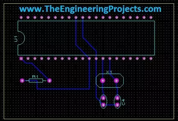
Hello friends, today's the last post of this Proteus tutorial. I have tried my best to explain everything but knowledge is limitless so explore this software, play with it and you will know many new things. Today's topic is about the PCB designing in Proteus. When you install Proteus, you have seen that along with ISIS there's also another package named as Proteus ARES. This Proteus ARES is used for PCB designing. You should also check the Arduino UNO PCB Design for Proteus ARES.
In order to design the PCB in Proteus ARES, first you need to make the circuit of that PCB in Proteus ISIS. You can also make PCB directly but I recommend that use Proteus ISIS first, its quite the easy approach as you don't need to do anything in it and the software in ...
Hello friends, hope you all are fine and having fun with your lives. Today's post is about How to increase Workspace in Proteus. It's our 3rd tutorial in Proteus series. Its quite a simple tutorial and along with this trick, I will also share few commonly used features or Proteus. Once, I was working on a simulation project in which I have to design a complete load management system in Proteus and it was quite messy as I have to include a lot of components and the area of Proteus got quite small for that and then I encountered this problem i.e. where to place the components.
You have seen in Proteus software that there's a blue rectangle which is considered as the workspace in Proteus. This area is constant and doesn't increase or decrease on its ...
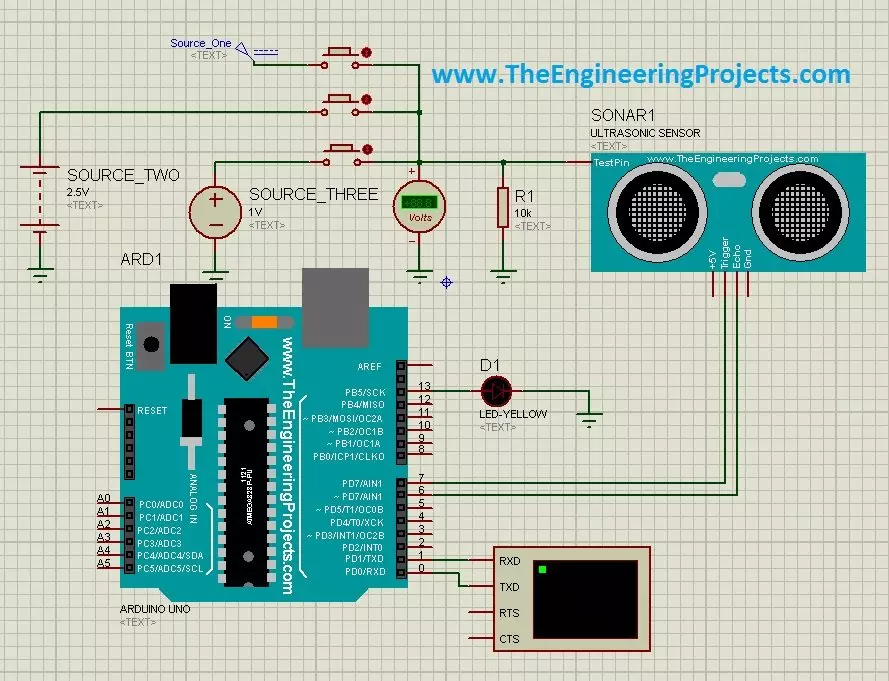
Hello friends, a few days ago I posted an Ultrasonic Sensor Library for Proteus, using which one can easily simulate ultrasonic sensor in Proteus. The post was highly praised by the reader and I have received quite good feedback from the followers. So, I thought of sharing some more examples related to it so that users can get a complete understanding of how to use Ultrasonic sensors in Proteus. Today, we are gonna have a look on different Ultrasonic Sensor Simulation in Proteus. If you haven't read the previous post then first have a look at it because without the installation of Ultrasonic Sensor Library in Proteus, you won't be able to use these examples. Ultrasonic Sensor is used widely in Embedded Systems.Today, I am gonna share three examples of Ultrasonic Sensor Simulation in Proteu ...
Hello friends, hope you all are having fun and enjoying life. Today's post is quite a simple one and is about designing of circuit diagram of buzzer in Proteus ISIS. Buzzer is quite a common electrical component which is used in almost every Embedded Systems project. For example, you have seen a simple UPS, it gives a beep each time the light goes off or it has depleted its battery. Buzzer is normally used for given some indication and normally this indication is kind of a warning.
Proteus has a builtin component for buzzer and its an animated component means it gives a sound (beep) when its turned ON. So, I am gonna use that one and will give you an actual beep on it. So, it won't be much difficult and quite a simple procedure. In this post, I am ...
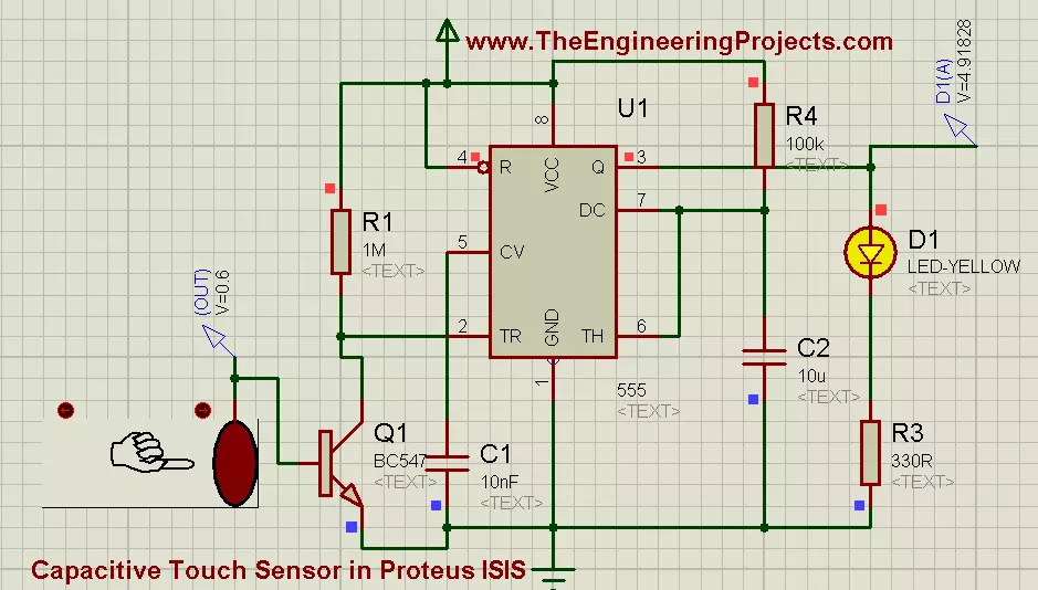
Hello friends, I hope you all are fine and enjoying. Today i am going to share my new project's tutorial which is How to use Capacitive Touch Sensor in Proteus ISIS. It is a very interesting project, and we will be using a 555 Timer while designing this project. If you recall our previous project tutorial which was Angle Control of Servo Motor using 555 Timer in Proteus ISIS, in which 555 timer was generating PWM and was controlling the rotating angle of servo motor.
Now in this project, we have a little different context and now we will be using a 555 Timer in collaboration with Capacitive Touch Sensor. First of all, lets have a little introduction of Capacitive Touch Sensor. Well, if we talk broadly then, in Electrical Engineering Capacitive Tou ...
Hello friends, hope you all are fine and enjoying good health. In the previous posts, we have seen How to design a 5V DC power supply in Proteus ISIS and after that we have also discussed How to design a variable DC Power supply using LM317.So, now today we will check how to design a DC Motor Drive Circuit in Proteus ISIS. DC motor is present in Proteus and quite easy to use. First we will simple drive it by applying voltage on its both sides i.e. direct method and after that we will automate it and will drive the circuit using PIC Microcontroller. The microcontroller I am gonna use will be PIC16F877A and the compiler will be MikroC Pro For PIC.
This tutorial is not a correct method of driving any DC motor. In this tutorial, I am just givi ...
Hey Learners, welcome to another exciting tutorial about electronics. We are talking about an audio amplifier using LM386. This is a very simple IC that we are going to used for the amplification of the audio signals. We shall go through the core postulation about the topic and then work on the practical implementation of the experiment. Just have a look at the topics of discussion:
Introduction to LM386 Audio Amplifier.
Components of LM386 Audio amplifier.
LM3386 Audio Amplifier Working.
Simulation of the LM386 Audio Amplifier Circuit in Proteus.
In addition, you will find interesting information in the DID YOU KNOW sections.
Introduction to LM386 Audio Amplifier
Audio signals play important role in many devices. These signals are used ...
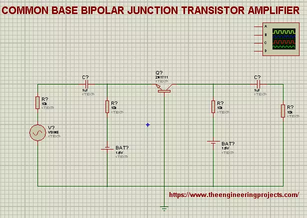
Hi mentees, Welcome to The Engineering Projects. If you are seeking for the Practical Implementation of Common Base bipolar Junction Transistor amplifier then you clicked at the best website because we'll cover the basic concepts and the procedure step by step.
So, Lets start the learning.
What is Common Base BJT Amplifier?
The precise definition of the Common Base BJT Amplifier is:
"The type of Bipolar Junction Transistor Amplifiers in which Base is Common to both emitter and Collector and Current gain is taken from the Base is called Common Base bipolar Junction Transistor Amplifiers."
Recall that a transistor has three regions i.e, Base, Collector and Emitter. Hence we design our Circuit in such a way that we get the output of current from ...
Hello friends, hope you all are healthy, wealthy and wise. Today's topic is about the control of stepper motor. In the last post we have seen How to control DC motor in Proteus, and now we are gonna see How to design a Stepper Motor Drive Circuit in Proteus ISIS. Stepper motors are usually of two types and the main difference between the two is in the number of wires used to control them. Mostly stepper motors use 6 wires to control them but few of them also have 4 wires to control them. Today we will have a look on the 6 wired stepper motor.
In stepper motor, there are electromagnets which gets polarized when we supply voltage to them and depolarized when we remove the voltage. These electromagnets act as a stater and when one side get magnet ...
Hello friends, hope you all are fine and having fun. In today's post we are gonna have a look at LM317 Voltage Regulator in Proteus. In the previous post, we have seen how to design a 5V Power Supply in Proteus ISIS, which I have designed using IC regulator 7805. Today I am going to share How to design LM317 Voltage Regulator Circuit in Proteus. This DC power supply is a variable one means you can set its output voltage to any level you want. In order to change its output value we have used a variable resistor and by changing its value you can change the output value. It is a basic level project and very simple but used as a base to design large industrial projects. In this project, we are going to control the speed of a DC Motor and the correspon ...