


LM317 Voltage Regulator in Proteus


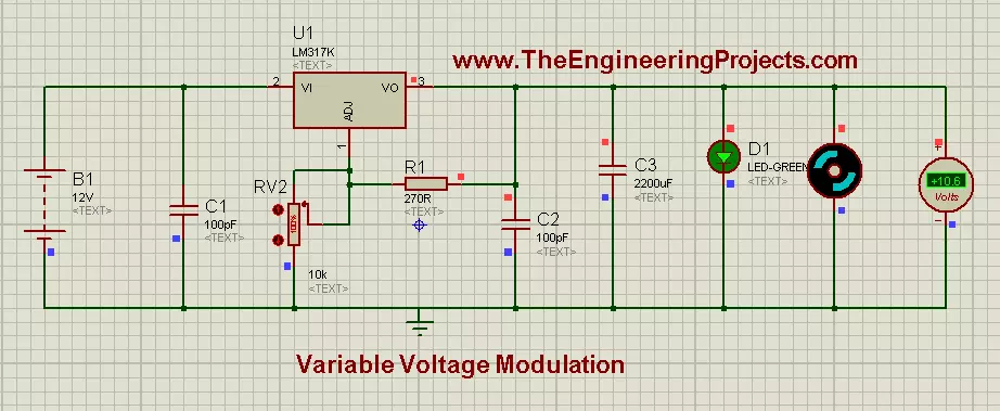
To design this, we will be using LM317k. Basically, it is a Voltage Regulator IC. It has 3 pins. Pin # 2 is for input voltages, marked as VI. Pin # 3 is for output voltages, marked as VO, and pin # 1 is used for Regulating Voltages and it is marked as ADJ. Further, if you notice the circuit diagram, which is given in the figure, then you will see that pin # 1 is connected to a Potentiometer. Potentiometer is a Variable Resistor device and it is also known as Voltage Divider. The feature of this electronic device is that, we can adjust the voltage through it according to our own choice. It operates on 12 Volts and it gives us ease that, we can adjust its voltages from 0 to MAXIMUM (which is 12 volts in most cases). Further if we notice the circuit, then we will see that a LED is connected in parallel with a simple DC motor and a voltmeter is also connected in parallel with Motor to monitor the voltages appearing across it. Above information was a little demo about the individual components of the circuit, now let’s be practical and move towards Hardware and see how actually Electronic components respond. You should also have a look at Introduction to LM317, if you wanna read all the basics about it. So let's get started with LM317 Voltage Regulator in Proteus:
LM317 Voltage Regulator in Proteus ISIS
-
You can download this complete LM317 Voltage Regulator simulation by clicking the below button but I recommend you to design it on your own so that you learn most from it.
-
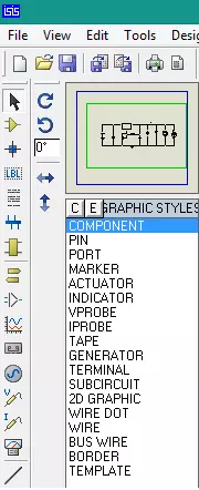
First of all, place all the components in Proteus workspace, as shown in image:
-
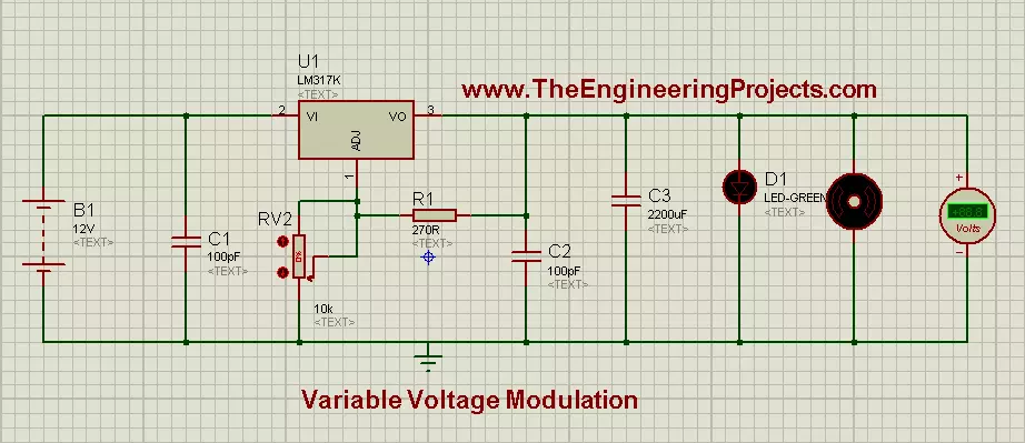
A 12-Volt DC supply is provided to input pin (# 2) of LM317 and potentiometer is connected to Adjustable pin of LM317, which is, pin # 1.
- At output pin we have connected DC Motor and a Voltmeter is also connected in parallel with Motor.
-
The complete circuit, ready for simulation is shown below in image:
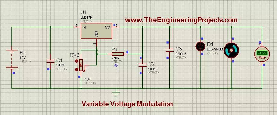
Stage # 1
- Set the potentiometer at 0% and run the simulation, you will notice that Motor will rotate very slowly in clock-wise direction and 1.25 volts will appear on the voltmeter across it. If all the connections are OK, and when you will run the simulation, LM317 Voltage Regulator simulation will look like as shown in the image below:
- If you don't want to use the variable resistance, then you should use this LM317 Calculator to get value of your second resistance.
Stage # 2
- Now, set the potentiometer value to 11% and you will see that, Motor will start to rotate with a faster rate and on voltmeter scale, we will see 6.40 volts. In this setting, the interesting thing is, LED will start to Flash and it will turn ON & OFF automatically. This phenomenon can be seen in images below:
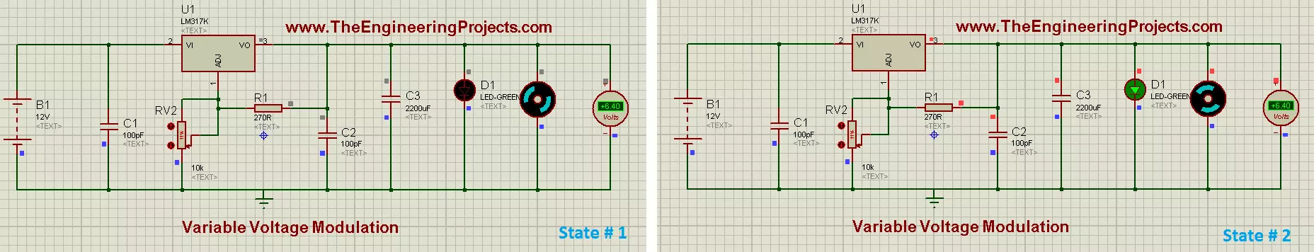
- Stage # 2 is our transient stage. When the potentiometers setting is below 11%, voltage appears across the motor and it also rotates but LED doesn’t glow. On the other hand, when potentiometers setting is above 11%, then LED glows continuously while motor also rotates as before, and voltmeter also gives some particular values of voltages appearing across the motor.
Stage # 3
- Now at final stage, set potentiometer to 100% and you will observe that motor is rotating with full speed and voltmeter reading will be 10.6 volts while LED is glowing continuously. This stage of the simulation can be seen in the image below:
Now, we can conclude that, LM317 is the monitoring device of this circuit. We can set the value of potentiometer according to our own choice and by this, the speed of motor can be controlled and also the corresponding voltages, appearing across it.
Here's the video in which I have given the detailed introduction of LM317 and have also run its simulation:Alright friends, that's all for today and I hope now you can easily design this LM317 Voltage Regulator. In the next post, I have discussed DC Motor Drive circuit in Proteus ISIS . Till than take care and be safe !!! :)


