How to use LDR Sensor in Proteus


So, in today's post, first I am gonna explain what is LDR sensor? and we will see where it is used and how it is used. After that I will design a simple circuit in Proteus in which I will turn control a LED using LDR sensor andwill make it ON and OFF. So, as usual let's start from the beginning so that the newcomers could also get benefit from it.
What is LDR Sensor?
- LDR is an abbreviation of Light dependent resistor. It is also known as photoresistor or photocell.
- Its symbol is shown in the below figure:

- LDR Sensor is used for the detection of light, internally it has a resistance which is sensitive to light as shown in the symbol.
- Whenever light falls on the LDR sensor, its resistance start decreasing and when it comes to dark then its resistance start increasing. Using the value of resistance one can easily detect whether there's light or not.
- It is normally used in light activated switches.For instance, you have seen the automatic street lights, which go ON when its night and automatically go OFF when its day time. In those street lights, LDR sensors are used.
Working of LDR Sensor
- As I explained above, it has an internaal resistance which is very sensitive to light intensity and varies according to it.
- So, one thing is quite clear that LDR sensor is an analog sensor. It gives us different values depending on the light intensity falling on it.
- Let's have a look on the simplest circuit of LDR sensor, which is shown in the below figure:
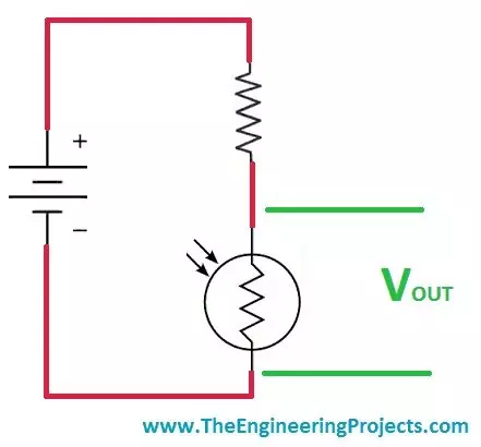
- Now if you check the above image you can see we have placed a resistor in series with the LDR sensor and have applied a voltage source across them.
- Now when the light will fall on the LDR sensor, its resistance will go LOW and in return the voltage across the LDR will also go LOW and as the LDR will come in dark, the resistance will go HIGH and in return the voltage will also go HIGH.
- Its the simplest working phenomena of LDR sensor. Now if you are using the LDR sensor with some microcontroller then what you need to do is simply give this intermediate connection of resistor and LDR to microcontroller.
Circuit Designing of LDR Sensor in Proteus
- Now we know the basics of LDR sensor and have also seen how it works so now let's design its circuit in Proteus.
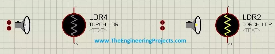
- There are two types of LDR sensors available in Proteus which are exactly the same in functioning but are different in operating. Both are shown in the below figure:
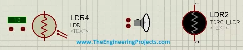
- The first one has a digital display along with it on which the voltage value is displayed while the second one a bit more animated and has a torch with it, so when you press the up arrow the torch will come closer and in other words the light is falling on the LDR and when you press the down arrow the the torch will go away and your LDR is in dark now.
- Both of these states are shown in below figure:
- Now you can see both the states quite clearly, in the first state torch is away so LDR is in dark while in second state, torch is close so LDR is ON.
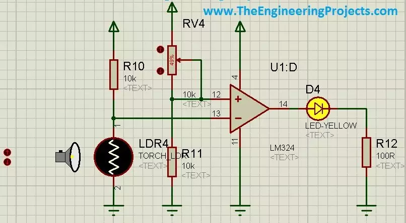
- So, now let's design their circuit to control a LED with LDR Sensor in Proteus. In order to do so, design this simple circuit in Proteus as shown in below figure:
- I have also designed this circuit on hardware and tested, it works perfectly as shown in the simulation.
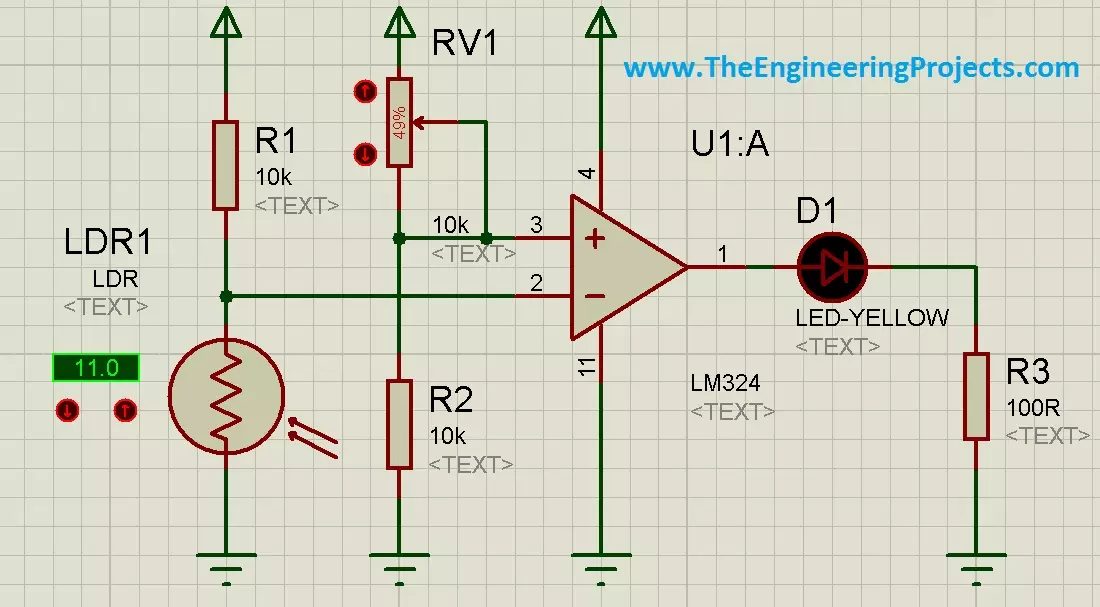
- Its a very simple circuit in which I am using a comparator and then giving output to LED. When the LDR is in dark then the LED will remain OFF and when the LDR will go into light then the LED will turn ON.
- Both of these states are shown in below figure:
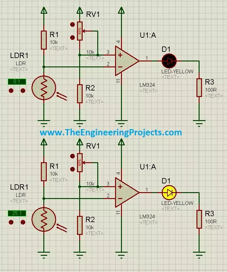
- Now you can see when the voltage on the digital display of LDR were LOW then the LED was OFF and when Iincreased the voltage then the LED went ON.
- Now let's check both of these states with the second LDR sensor in Proteus, which are shown in the below figure:
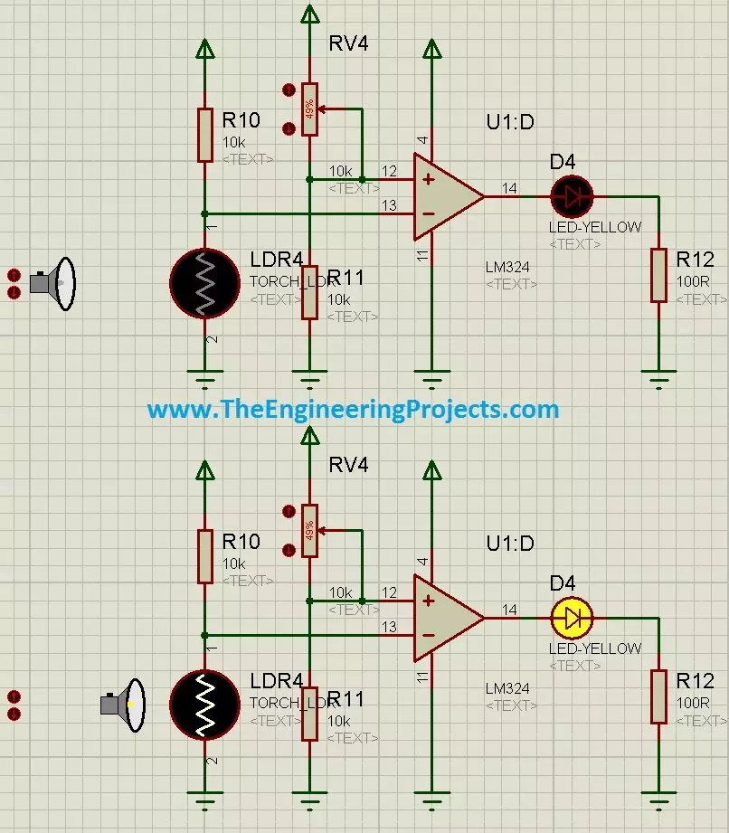
- Again quite obvious, when the torch was away then LDR was in dark and the LED was OFF but in second state when I moved the torch close the LED went ON.
- Here's the Proteus Simulation of LDR sensor attached below, download and play with it. :)
Download LDR Sensor in Proteus Simulation
That's all for today, if you have any problem ask in comments and I will reply them. Take care and have fun !!! :)