


Design a 5V Power Supply in Proteus


While designing a 5V Power Supply in Proteus ISIS, we will be using Voltage Regulator IC, which is commonly known as 7805. This voltage regulator is used to regulate or change the voltage level of supply voltage. As we all know, most of the batteries available in market are of 12 volts. For example, if you have UPS at your homes then check its battery, it will be of 12V. Similarly, the battery of car or motorcycle is also of 12V. So, 12V has become the standard of electrical batteries. Now, we have known that all batteries are of 12V but the problem comes when we are dealing with sensitive electronic components because they are all designed to operate on 5 volts. Now, as I described earlier that, voltage source available is 12 volts and the operating equipment needs 5 volts to operate. So, we need an intermediate source or such type of DC Power Supply, which can convert the source voltage (12 volts) to operating voltage (5 volts). This problem is eliminated by using 7805 IC, and that’s why it is called Voltage Regulating IC.
So dear Friends, today we will design a 5V power supply, which will be able to change Voltage Level and will provide us our desired voltage. But as I always say, that practice makes a man perfect. Try to design it yourself so that, you also get to know the real application of Voltage Regulator IC. So, let's get started with designing of 5V power supply in Proteus ISIS.How to Design a 5V Power Supply in Proteus
- You can download the complete simulation of 5V Power Supply in Proteus by clicking the below button:
- Voltage Regulating IC 7805 has 3 pins.
- Pin # 1 is used as input pin and it is connected to supply voltages. It is marked as (VI). DC +12 volts are applied to this pin.
- Pin # 2 is called common or ground pin. It is marked as (GND). The whole circuit's common is applied to this pin.
- Pin # 3 is the output pin of 7805. If 12 volts are applied to its input than it automatically generates 5 volts on this pin. This pin is marked as (VO).
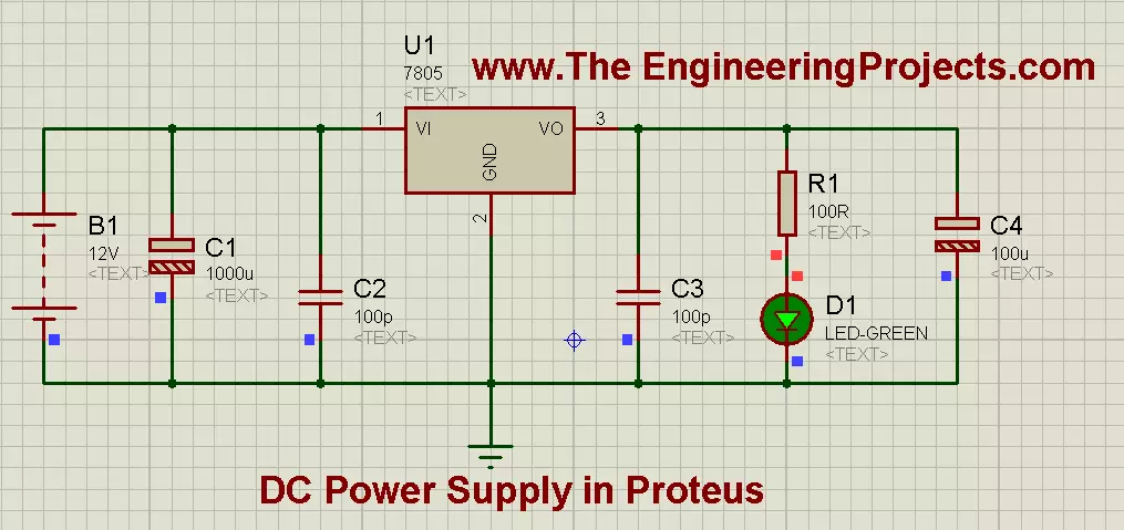
- Now, moving towards the designing of the hardware, first of all place all the components in Proteus workspace, as shown in image below:

- In Hardware implementation, first off all apply source voltage (12 volts) to the input pin of 7805 IC. 2 capacitors are also connected in parallel with the source voltage and their ratings are 1000 uf and 100pf respectively.
- On the other side of IC, we also connect 2 capacitors parallel to the gained output voltage (5 volts), and their ratings are 100pf and 100uf respectively. And a LED is also connected in parallel on the load side.
- If you have placed all the components in their perfect place and all the connections are OK, then the resultant proteus simulation will look like as shown in the below image:

- Now if you closely observe the above image then you will notice that Capacitors connected across the 12 volts are of HIGH rating while the Capacitors connected across LED are of LOW rating. The purpose of applying capacitors is to remove noise from our DC voltages. As, we all know that DC voltage source available in market is not that much pure. So, to get pure DC wave Capacitors are connected across it.
- Now when you will run the final simulation then it will look like, as shown in the image given below:
- As you can see that when i ran the simulation, the LED started to glow. Now here is an important thing to note that i have applied a resistance in series with LED. The value of resistance is very low, and very low voltages appear across this resistor. This resistor limits the current and if we directly connect the LED then, their will be chances that the LED may burn out.
- We can justify it as: From ohms law : V=IR, and by rearranging it, we get : I=V/R .
- Now if we remove resistor then R=0, which means: I=V/0 and it lead us to conclude that: I= infinity or maximum in this case. So the only purpose of the resistor is to limit current.
Alright friends, that’s all for today, I hope now you can design a 5V power supply quite easily in Proteus. If you have some queries, then ask in comments. Subscribe us via email to get these tutorials straight in your inbox. In the next tutorial, I have discussed Variable Voltage Modulation using LM317 in Proteus ISIS.


