Hello readers, I hope you all are doing great. In today's tutorial, I am going to share a detailed Introduction to Proteus. It's our first tutorial in Proteus series. Today's tutorial is for beginners but still I would suggest you to read it once, as I am going to explain why Proteus?
Throughout our Engineering Course, we have to design a lot of electronics or embedded circuits and it's always a best approach to simulate these circuits first on some simulation software i.e. Proteus, PSPice etc., before assembling them on actual hardware. Among these simulation software, Proteus is my favorite one so let's get started with detailed Introduction to Proteus:
Introduction to Proteus ISIS
Proteus Design Suite (designed by Labcenter Electronics Ltd.) is a software tool set, mainly used for creating schematics, simulating Electronics & Embedded Circuits and designing PCB Layouts.
Proteus ISIS is used by Engineering students & professionals to create schematics & simulations of different electronic circuits.
Proteus ARES is used for designing PCB Layouts of electronic circuits.
It's available in four languages i.e. English, Chinese, Spanish & French.
Why use Proteus ?
"Our circuit is working perfectly on Proteus but when we have implemented it on hardware, it's not working." I receive a lot of such questions from engineering students, that's why, I am explaining what's the real purpose of Proteus:
Proteus is quite lenient in circuit designing and it works on ideal conditions i.e. if you don't add pull up resistors in Proteus simulation, then it won't give garbage value.
Proteus is also used for PCB designing, we use Proteus ARES for that. ( We will discuss it in upcoming lectures )
So, when I am working on some electronics circuit, then I first design the simulation on Proteus ISIS and once I got sure that everything's working fine then I design its circuit on either the vero board or the bread board and again I perform some real world testing & when I got sure that my circuit is fully working then I design its PCB in Proteus ARES.
Proteus is also used for designing/testing programming codes for different Microcontrollers i.e. Arduino, PIC Microcontroller, 8051 etc.
In Embedded projects, we need to design a programming code for Microcontrollers and for designing such codes you have to perform a lot of testing, which involves uploading code to Microcontroller. So, in such projects, Proteus is a great relief. Let's say, you have to print some strings on 20x4 LCD, then its quite annoying to burn the Microcontroller several times for typographical errors. Instead, design a circuit in Proteus and test your code in the simulation and once you are sure that you are getting perfect output then burn your PIC Microcontroller and test it on real hardware. Quite easy and handy. In the coming classes, I will show you how to burn code in Microcontrollers in Proteus.
Note: In code testing, there's again a possibility that you get different results in real hardware but its quite rare and mostly happens in delay functions.
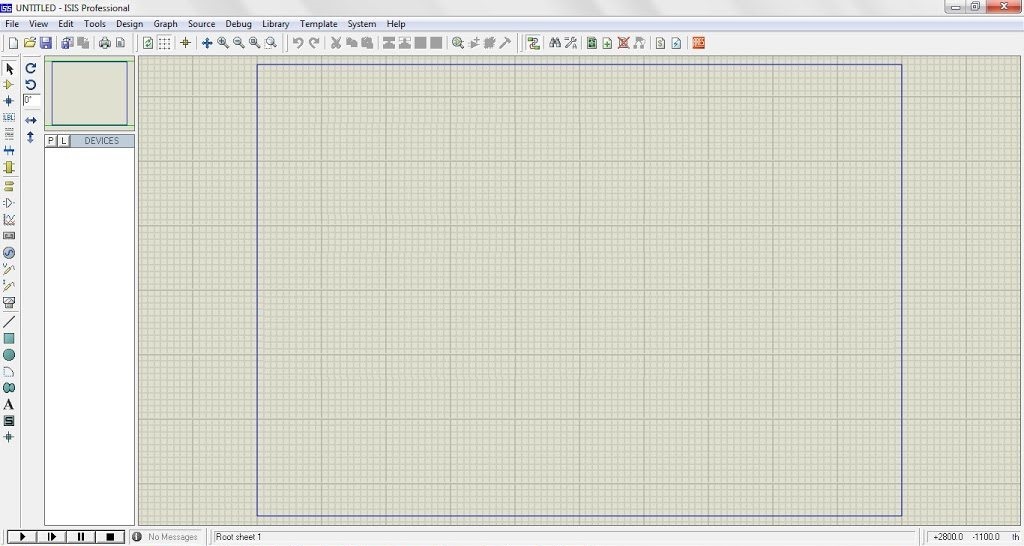
Click on Proteus ISIS and it will open up as shown in below image.
In the central area surrounded by blue lines, we design our circuit i.e. place the components and then join them together.
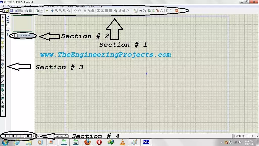
As you can see in above figure that we have a lot of icons in Proteus software, so let's first understand these sections one by one.
In the below image, I have divided the Proteus font-end in four sections:
Section 1 is a toolbar which you would have seen on many simulation software, it has simple functionalities i.e. first icon to create a new layout, second one to open an existing layout, next one is to save layout, then there comes few zooming options and few other tools which we will discuss in coming tutorials.
Section 2 has two buttons. P is used to open the components list and E is used for editing purposes, like you want to edit the properties of any component then simply click on that component and then click on E and it will open the properties of that component and you can easily edit it.
Section 3 has different tools, used for designing circuits, we will discuss them in detail, at the end of today's tutorial.
Section 4 is the remote control section of Proteus, as it contains four buttons i.e. Play, Step, Pause & Stop. In order to run the simulation, we have to click on this play button.
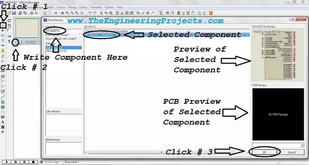
Component Selection in Proteus ISIS
As shown in below image, click on the icon that says Click # 1, it's a Component Mode Icon.
After that click on P button and a new window will open up named Pick Devices.
In this new window there's a textbox on which Keyword is written, this text box is used for the component search.
Proteus database has unlimited components in it so now in order to get your desired component, you have to search for it as I did.
I have searched for PIC16F877A and Proteus provided me that component along with its preview in top right corner and PCB package ( if available ). Unfortunately, my Proteus doesn't have the PCB preview of PIC16F877A that's why it's blank.
In order to add the component in Proteus workspace, either double click on it or click on the OK button.
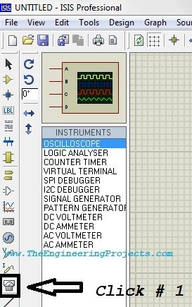
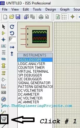
Instruments in Proteus ISIS
There are few measuring instruments available in Proteus, which you can open by clicking the Instruments Icon, as shown in figure on right side.
First one is oscilloscope, we use it for viewing the behavior of different signals generated.
Another important instrument is Virtual Terminal, it is shown on the fourth number. This Virtual Terminal is used for checking data coming through Serial Port.
Then there's Signal Generator, it is used to generate signal like sine wave of desired frequency.
We also have Voltmeter & Ammeter for both AC & DC.
We will discuss them in detail in our coming lectures.
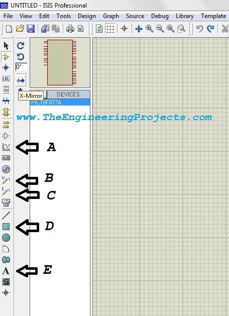
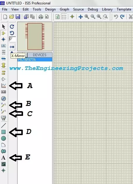
As you can see in figure on right side, Icon A is called Graph mode, used to create graphs of voltage and current. It has different style of graphs.
Icon B and C are voltage and current probes respectively. Suppose you have designed some circuit in Proteus and you want to check the value of voltage at any point in the circuit. In order to do so, simply select this voltage probe and place it there and when you run your circuit, the probe will show the value of voltage above it and same for current probe.
Icon D is used when we want to design our own component in Proteus.
Icon E is a simple text editor, used for placing labels, warning or components names etc.
So, that was all for today. I hope you have enjoyed this detailed Introduction to Proteus. If you have any question, feel free to ask in comments and also subscribe through email to our mailing list, so that you don't miss any part of this tutorial series. Stay blessed. Take care.