


Buck Converter using MOSFET Gate Driver in Proteus


- Introduction to MOSFET Gate Driver.
- Circuit of MOSFET Gate Driver.
- Working of MOSFET Gate Driver.
- Simulation of MOSFET Gate Driver in Proteus.
- Applications of MOSFET Gate Driver.
Introduction to MOSFET Gate Driver
We all know MOSFET is a type of transistor and is used in a wide range of circuits. It has many interesting features and the characteristics of MOSFET are at the fingertips of electrical and electronic engineers. The circuit of the MOSFET Gate Driver may be new for many students so let's have a look at its definition:"The MOSFET Gate Driver is a type of DC to DC power amplifier that in the form of on-chip as well as discrete module in which we use MOSFET as the gate driver IC, the low power is taken as input from MOSFET and high power is obtained its gate terminal and vice versa according to need."MOSFET is used in this circuit because it is commonly used in switching devices where the frequency ranges from hundred of KHz to thousands of KHz. It is mostly used in appliances where we need DC to DC amplification. It is used in computers to low their temperature during their performance. The MOSFET Gate driver is used to change the value of DC according to the circuit of the appliances.DID YOU KNOW?
The name of the MOSFET Gate Driver is due to its characteristic to have the high current drive gate input of a Transistor. We use the MOSFET because it is a gate driver IC.
- High side drivers.
- Low side Driver.
- Isolated Drivers.
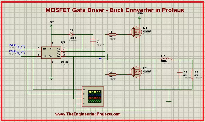
Circuit of MOSFET Gate driver
When we look at the circuit of the MOSFET Gate drive, we found there are some basic as well as some special components in the circuit. In addition to MOSFET, the circuit consists of resistor, capacitor, inductor and IR2101. Let's look at their functions:MOSFET
- Metal Oxide Semiconductor Field Effect Transistors have a thin layer of silicon oxide between Gate and channel. It four terminals: Gate, Drain, Source.
IR2101
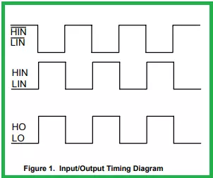
It is IC that works very great with MOSFET. We use it in the MOSFET Gate driver to insert the voltage in the Gate terminal of the MOSFET in the form of pulses. We define the IR2101 as:"It is seven pins, high power, high voltage, MOSFET and IGBT driver that has independent high and low channel references."The detail of the pins is given as:
- Vcc: This Pin is for Low side and logic fixed supply voltage.
- Vs: It is for High side floating supply offset voltage.
- Hin: High side gate driver output is taken by this pin.
- HO: We get High side gate drive output through this pin.
- Lin: Low side gate driver output is taken by this pin.
- LO: Low side gate drive output is obtained through it.
- COM: we get Low side return from this pin.
Working of MOSFET Gate Driver
The working of the MOSFET Gate Driver start when the power is generated from power terminals.- The IR2101 starts with the power terminal, the input pulse generators convert this power into the special length as set by the user.
- These pulses Enter at the gate terminals of MOSFETs.
- Both of these MOSFETs do not turn on at the same time. They work in a loop so that if the high side MOSFET is turned on then the other is off and vice versa.
- The MOSFET M1 on the upper side of the circuit is considered at the High side of the driver and the MOSFET M2, on the lower side of the circuit is at the Low side driver.
- After some time, when the voltage becomes greater than the threshold voltage of MOSFETs, they start working.
- The terminals of MOSFETs are connected with the capacitor.
- The aim of this circuit is to charge the capacitors. Hence when the MOSFET starts working, the charging of the capacitor takes place.
- The pulses reach both the MOSFET at a very specific time due to IR2101.
- Once the capacitor C2 is fully charged, it starts the discharging power and this discharging power from the inductor as well and at last, it goes to the ground terminal.
- In this case, the polarity of the inductor changes and in this way, the energy stored in the capacitor is discharged.
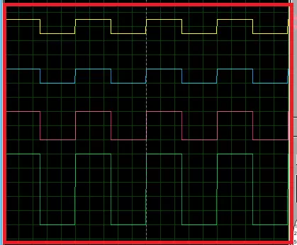
- Hence at the end, when we check on the oscilloscope, we get the changed output pulse from the input.
Simulation of MOSFET Gate Driver in Proteus ISIS
Material Required for MOSFET Gate Driver
- MOSFET
- IR2101
- Resistor
- Capacitor
- Inductor
- Ground Terminal
- Power Terminal
- Pulse Generator
- Start your Proteus Software.
- Make a new Project.
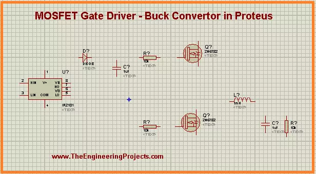
- Click at "P" button to choose the first five components for the experiment one after the other.
- Arrange all the components in the working area according to the arrangement given next:
- Go to Terminal Mode> Ground and add ground terminal with the required components of the circuit.
- Repeat the above step with the power Terminal.
DID YOU KNOW?
The efficiency of MOSFET Gate driver is more than 90% in many cases.
- Go to Instrument Mode and take the Oscilloscope from there. Now, arrange it just below the circuit.
- Connect all the components with the help of connecting wires by carefully following the image given next:
- Double-tap the components one by one and change the default values according to the table given next:
Components Values R1 10R R2 10R R3 60R L1 500u C1 4.7u C2 60u Pulse 1 Pulse (High) voltage =5v, frequency 1k, Pulse Width 50% Pulse 2 Pulse (High) voltage =5v, frequency 1k, Pulse Width 50% - Tap the play button at the lower-left corner of the screen to simulate the graph.
- Set the values of voltage and current through the nob to see a clear output.
Applications of MOSFET Gate Driver
- MOSFET Gate driver is used in DC to DC converter.
- It is used in the conversion of high voltage to low voltage.
- It is mainly used to reduce heat in many circuits.
- Due to its functions, it is useful in extending battery life.
×
![]()


