Hello friends, I hope you all are doing great. Today, I am going to share the new Ball and Beam PID Control Lab Library for Proteus, the third of our University Lab series. The ball and beam is the most famous unstable plant in control teaching: a ball rolls along a beam, a motor tilts the beam, and the controller has to bring the ball to a chosen spot and keep it there. Leave the beam alone for a moment and the ball rolls off the end. It is the experiment that shows, better than any other, why a controller needs its derivative term, and the same ideas balance robots, steer rockets and keep a camera level.
Ball and Beam PID Control Lab Library for Proteus
Latest version: V1.0 (November 2026, this tutorial)
Other component libraries: C945 Transistor · PC817 Optocoupler · Relay Module · Resistor · 5 mm LED · Designer Colour LED · Push Button · Active Buzzer · Electrolytic Capacitor · Ceramic Capacitor · Tantalum Capacitor · Film Capacitor · 1N4007 Diode · Zener Diode · Schottky Diode · Supercapacitor · Photodiode · RGB LED · Bridge Rectifier · Flashing LED · Bi-Colour LED · SMD LED · Slide Switch · Toggle Switch · Rocker Switch · Micro Limit Switch · Emergency Stop Switch · SMD Resistor · Power Resistor · Resistor Network · Potentiometer · Trimmer Potentiometer · Slide Potentiometer · NTC Thermistor · DIP Switch · Fuse · Passive Buzzer · Mini Speaker · 7-Segment Display · LED Bar Graph · IR / UV LED · Small Transistors · TIP122 Darlington · N-MOSFET · P-MOSFET · PC817 Optocoupler · Filament Bulb · Power LED · Voltage Regulator · SCR and TRIAC · Inductor · Toroid Inductor · Crystal · Temperature Control Lab · DC Servo Lab · Magnetic Levitation · Rotary Pendulum · Coupled Tanks · AD8232 ECG · MyoWare EMG · GSR Sensor · MAX30205 · MCP4725 · MCP3008 · LM358 · NE555 Timer · INA128 · 74HC595
Helping Tools
- Serial Monitor Advance: a serial terminal window for the UART of your board
- Serial Monitor Expert: the serial monitor with extra debugging tools
- LCD Library for Proteus V3.0: 16x2, 20x4 and I2C LCDs to show your readings
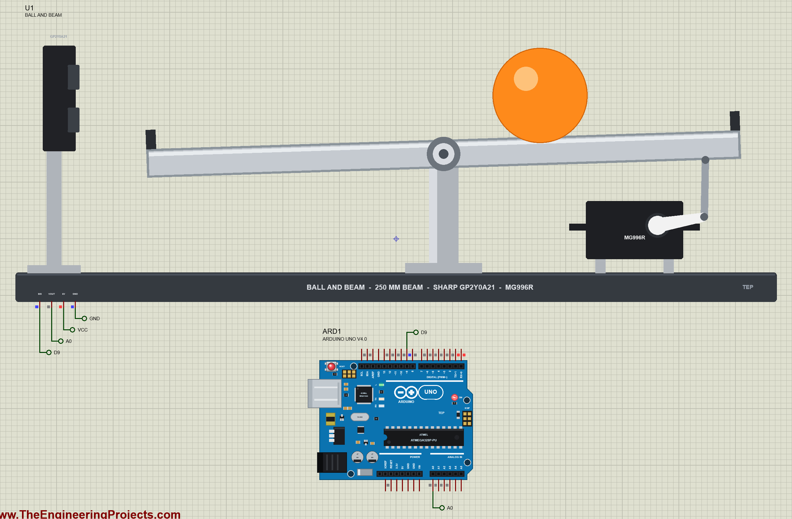
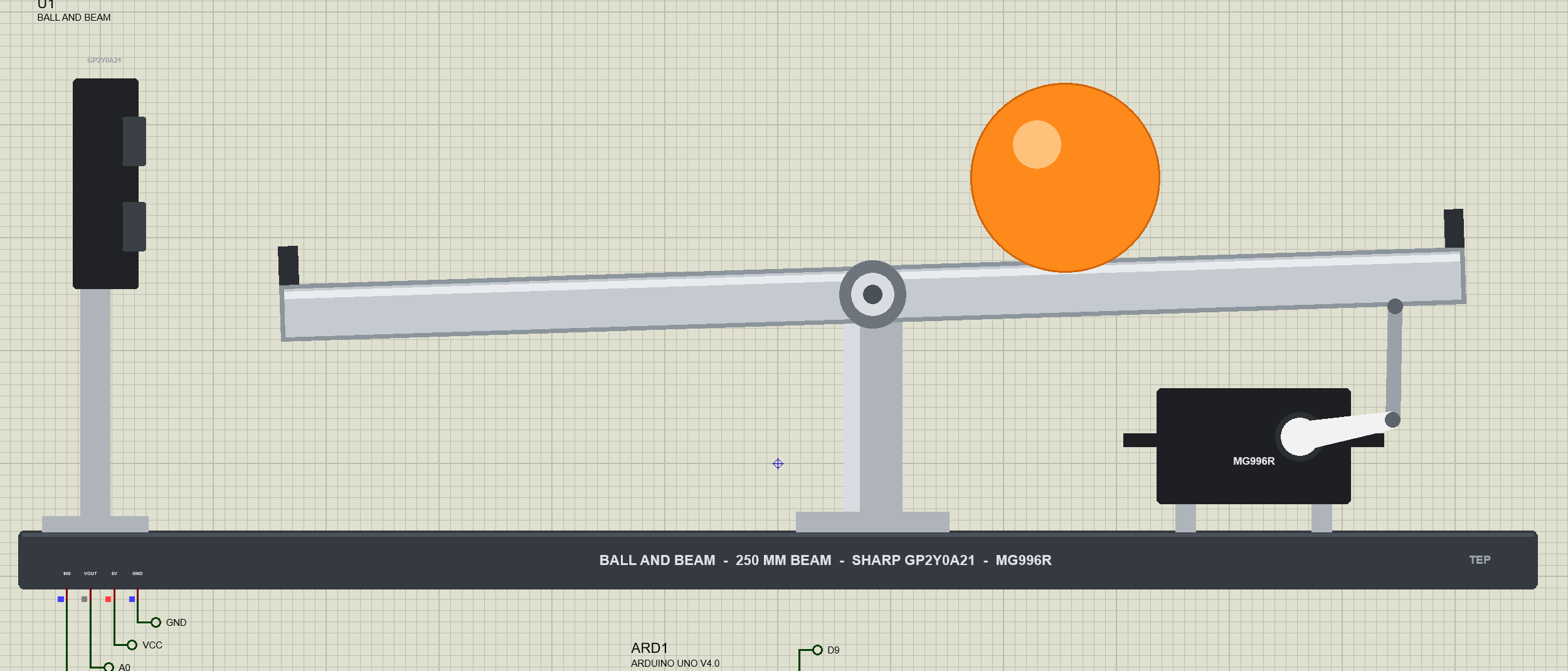
Our library brings that lab into Proteus at true scale. It is our own ball and beam: a 250 mm aluminium channel on a pivot, a 40 mm table-tennis ball rolling in it, an MG996R servo tilting the beam through a horn and a link, and a Sharp GP2Y0A21 infrared sensor at one end measuring how far away the ball is. The physics is worked out from the parts: how a hollow ball rolls on two rims, how the linkage turns the servo's angle into the beam's, and the sensor's real curve with its 38 ms measuring cycle. The pop-up gives the model, the PD gains for the response you ask for, and the overshoot and settling time of every move. The demo makes three PD moves and one with half the derivative, from an Arduino UNO.
NOTICE: Our team has put a lot of effort into these small parts: the bodies, the animation and the pop-ups are all our own design, and you get them free. Your feedback is the fuel that keeps us going, so please tell us what you think in the comments below or in the Ball and Beam board of our forum. And if our free libraries help you, you can buy us a coffee. So, let's get started with the Ball and Beam PID Control Lab Library for Proteus:
What is a Ball and Beam?
A ball and beam is a beam that can tilt about a pivot in its middle, with a ball free to roll along it. Tilt the beam and the ball rolls downhill, faster and faster; the only way to stop it is to tilt the beam the other way before it reaches the end. The controller sees the ball's position through a sensor and sets the beam's angle through a motor. Our lab is 320 mm long, drawn at its true size, so it is a lot bigger than the UNO beside it: a dark aluminium base, a pivot post carrying a 250 mm U-channel with end stops, the ball, the servo under the right end, and the sensor on a bracket at the left end, 30 mm before the beam starts.
| The ball and beam | |
|---|---|
| Size | 320 mm base, 250 mm beam, 40 mm ball |
| Beam | aluminium U-channel, 20 mm wide inside, pivot in the middle, end stops |
| Ball | table tennis, 40 mm, a thin shell |
| Servo | MG996R, a 20 mm horn and a link 110 mm from the pivot; 1500 µs level |
| Sensor | Sharp GP2Y0A21 infrared distance sensor, 10 to 80 cm, an analog output |
| Pins | SIG from a servo pin, VOUT to an analog pin, 5V and GND |
How the Ball Rolls
A ball on a tilted beam does not slide, it rolls, and rolling takes some of the energy: part of the pull of gravity spins the ball instead of moving it. How much depends on where the ball's mass is. A table-tennis ball is a thin shell, its moment of inertia two thirds of its mass times its radius squared, more than a solid ball's. And in a U-channel the ball does not touch the bottom: it rests on the two rims, 10 mm either side of its centre line, so it rolls on a smaller radius, 17.3 mm instead of 20, and spins faster for the same speed. Together these give an acceleration of 0.529 g, or 5.19 m/s², times the sine of the beam's angle. A small rolling loss and the end stops, which bounce the ball back with 30 % of its speed, complete the model.
From Servo to Beam
The servo does not tilt the beam directly. Its horn, 20 mm long, pushes a link up and down, and the link lifts the beam 110 mm from the pivot. So the beam turns through about 20/110 of the horn's angle in radians: when the servo turns 45 degrees the beam tilts by 7.4 degrees. A hobby servo takes a pulse every 20 ms and turns to the angle the pulse's width asks for; on our lab 1500 µs is level and each degree is 11.1 µs, from 500 to 2500 µs for -90 to +90 degrees. The MG996R turns at up to about 375 degrees a second at 5 V, which is fast compared with the ball but not instant.
The Sensor
The Sharp GP2Y0A21 measures distance by triangulation: it shines an infrared spot and sees where the reflection lands on a small detector. Its output is not a straight line: 2.30 V at 10 cm, 1.30 V at 20 cm, falling more slowly further away, and under about 6 cm it folds back, so the ball must stay clear of the sensor's end. It measures once every 38.3 ms and holds its output in between, which adds a delay of a few tens of milliseconds. The lab uses the same datasheet curve as our Sharp IR library, for the ball's near surface, with a few millivolts of noise.
The Model: A Double Integrator
For small angles the three pieces multiply into one number: the ball's acceleration per degree of servo, K = 1.648 cm/s² per degree. The ball's position is that acceleration added up twice, and a plant like that, a double integrator, has no natural resting place: any tilt left in place sends the ball to the end. That is why there is nothing to identify with a bump test here. The model comes straight from the physics, and the pop-up shows it on the main page and the Check page.
PD Control for a Double Integrator
A proportional controller alone tilts the beam in proportion to the error, and the ball swings back and forth around the target forever, like a weight on a spring, because nothing takes the energy out. The derivative term, a tilt in proportion to the ball's speed, does: it is the damper. With servo angle = Kp x error + Kd x speed, the loop behaves like a spring and damper with ωn² = K Kp and 2ζωn = K Kd. The pop-up designs for 5 % overshoot, ζ = 0.69, and a settling time you set with the property TSET, 3 s by default, which gives ωn = 1.93 rad/s, Kp = 2.27 degrees per cm and Kd = 1.62 degrees per cm/s, or 25.2 µs per cm and 18.0 µs per cm/s of servo pulse.
Features of the Ball and Beam PID Control Lab Library for Proteus
- The real look, at true scale: a 320 mm lab with the beam, the ball, the MG996R with its horn and link, and the GP2Y0A21; at Run the beam tilts and the ball rolls on the sheet.
- Real physics: a hollow ball rolling on two rims, the linkage, the servo's speed, the end stops.
- A real sensor: the GP2Y0A21's datasheet curve, its 38.3 ms cycle and its noise.
- Exact servo timing: every edge of the servo pulse is timed.
- The model and the gains: x'' per servo degree from the physics, and the PD gains for 5 % overshoot and the settling time you choose.
- Every move measured: rise time, overshoot, peak time and settling time.
- A pop-up: the lab from the side, the ball, the beam and the servo since the start, eight live values, graphs, an event log and a check page.
- A complete package: about 1.3 MB with the library, our Arduino UNO V4.0 and the demo, without the source code of the model.
The Ball and Beam in Proteus
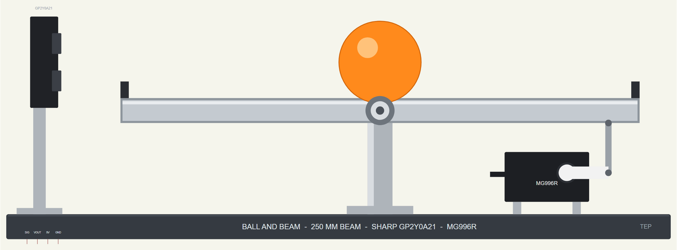
The device is BALLBEAMTEP in TEPBALLBEAM.LIB, under Control Labs, with the prefix U and the model TEPBALLBEAM.DLL, a mixed model: the servo's pulse is digital and timed edge by edge, the sensor's output is analog. Search BALLBEAM in Pick Devices. Its four pins are on the bottom edge of the base, at the left: SIG for the servo's pulse, VOUT for the sensor, 5V and GND. Because it is drawn at its true size, the lab needs an A3 sheet.
The Properties
| Property | What it does |
|---|---|
| The ball at the start (BALLX) | cm from the sensor, 5.4 to 25.6 |
| Sensor noise (NOISE) | mV RMS on VOUT, 3 by default |
| Settling time (TSET) | the pop-up's PD gains are for 5 % overshoot and this settling time, 3 s by default |
Download Ball and Beam PID Control Lab Library for Proteus
Click the button below to download Ball-and-Beam-PID-Control-Lab-Library-for-Proteus-v1.0.zip (about 1.3 MB, without the source code of the models):
Ball and Beam Library for Proteus V1.0- README.txt: installation, the demo, the wiring, troubleshooting and the limits.
- Proteus Library Files:
TEPBALLBEAM.LIBand ourArduinoV4TEP.LIB. - Proteus Model Files:
TEPBALLBEAM.DLLandTEPARDUINO.DLL. - Arduino Code: the demo sketch.
- Proteus Simulation: the demo project, its HEX file and copies of the DLLs.
No Proteus yet? Read How to Download and Install Proteus 7 and 8. New to libraries? Follow How to Install a New Library in Proteus.
How to Install Ball and Beam PID Control Lab Library for Proteus
- Close Proteus and extract the whole zip file, for example to your Desktop.
- Copy the files from Proteus Library Files into the LIBRARY folder of Proteus.
- Copy the files from Proteus Model Files into the MODELS folder.
- Delete
TEPBALLBEAM.IDXfrom the LIBRARY folder if it is there. - Start Proteus, press P and search for BALLBEAM.
Demo: Three PD Moves and One with Half the Derivative
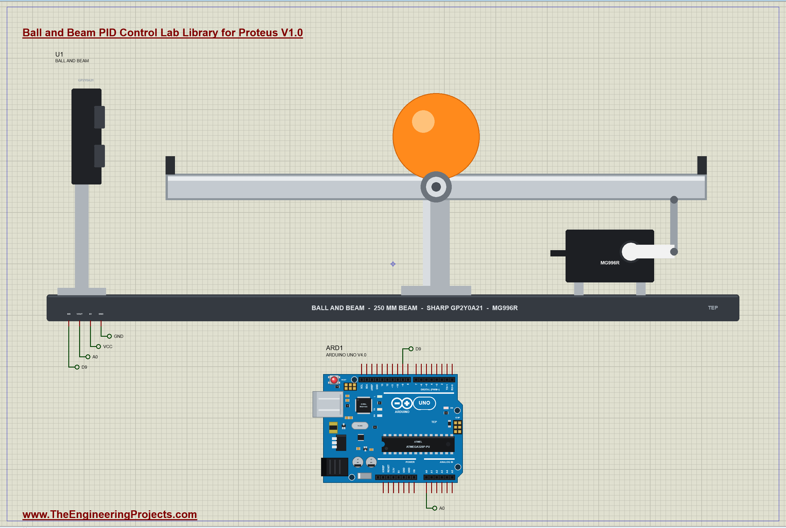
The demo is just the lab and our Arduino UNO Library for Proteus V4.0, with its built-in monitor, the same window as our TEP Serial Monitor Advance for Proteus. The lab's SIG goes to D9, driven by the Arduino Servo library, VOUT to A0, and 5V and GND to the rails. Open BallBeam-PD-ArduinoUnoV4.pdsprj; the sheet is A3, with the lab across the top and the UNO below it.
The Sketch
The sketch reads the sensor four times, turns the voltage into centimetres with a power law fitted to the sensor's curve, and adds the ball's 2 cm radius, so it works with the ball's centre:
  float v = s / 4.0 * 5.0 / 1023.0;
  if (v < 0.3) v = 0.3;
  return 27.19 * pow(v, -1.189) + 2.0;
Every 40 ms, about once per sensor reading, the PD loop works out the ball's speed from the last two readings, smooths it a little because the sensor is noisy, and sets the servo. A ball too far from the sensor lifts the servo's end of the beam, and the ball rolls back:
    float v = (x - xPrev) / (PERIOD / 1000.0); xPrev = x;
    speed = 0.6 * speed + 0.4 * v;                // (a little filtering: the sensor's noise)
    u = constrain(KP * (x - ref) + kd * speed, -45, 45);
    servo.writeMicroseconds(1500 + u * US_PER_DEG);
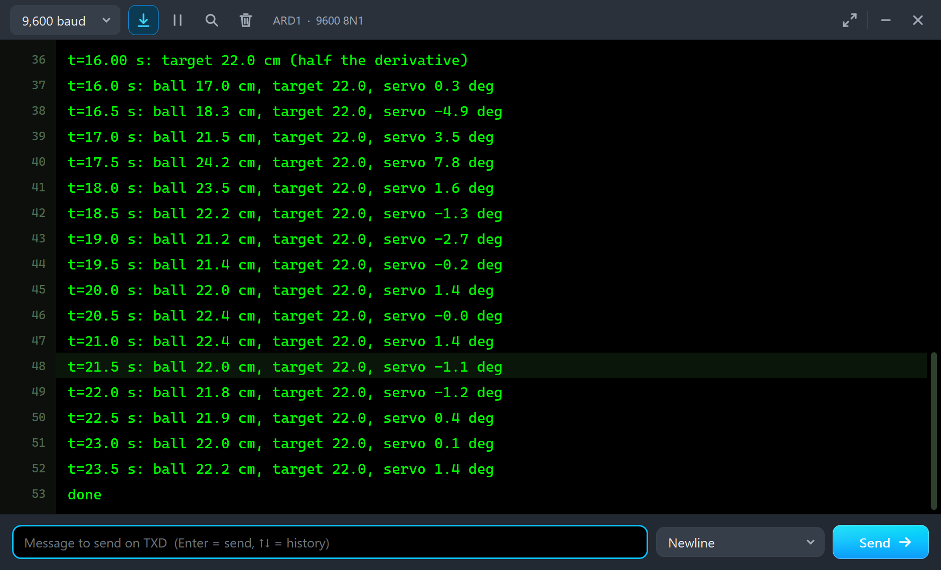
The ball starts at rest at 15.5 cm from the sensor, over the pivot. At 1 s the target goes to 21 cm, at 6 s to 12 cm, and at 11 s to 17 cm, with the pop-up's gains, 2.27 degrees per cm and 1.62 degrees per cm/s. At 16 s the target goes to 22 cm with the derivative halved. Every half second the sketch prints the ball, the target and the servo's angle.
Run the Demo
Open the project and press Run. The UNO prints its banner and starts the servo's pulses at 1500 µs, the beam level, and the ball sits still over the pivot. The demo runs 24 simulated seconds, which Proteus ran in about a minute and a half on our PC. On the sheet the beam tilts and the ball rolls, redrawn a few times a second. Click the lab to open its pop-up; everything below is from that one run, the demo exactly as it ships.
A PD Move, Moment by Moment
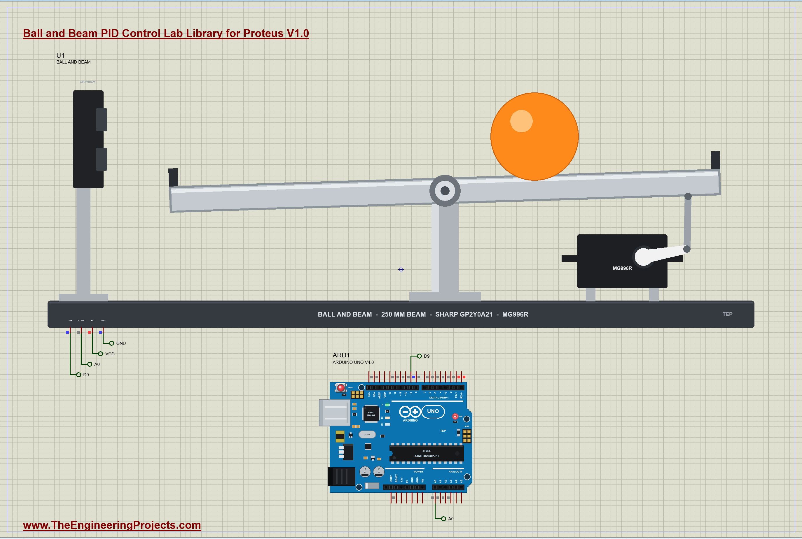
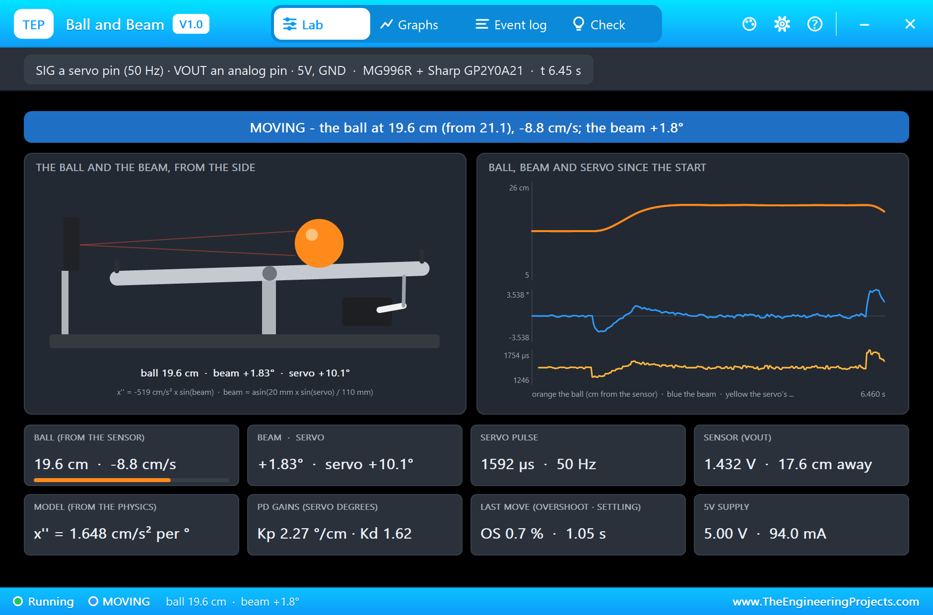
The pop-up was opened at 6.45 s, in the middle of the second move, from 21.1 to 12 cm. The banner reads MOVING - the ball at 19.6 cm (from 21.1), -8.8 cm/s; the beam +1.8°. The servo is at +10.1 degrees, a 1592 µs pulse, lifting its end of the beam, and the ball is rolling back towards the sensor, which reads 1.432 V for the ball's surface 17.6 cm away. On the trend, the first move is one smooth S-shaped step of the orange ball; the blue beam first tilts one way to start the ball, then the other way to stop it. That second tilt, the braking, is the derivative at work.
The PD Moves
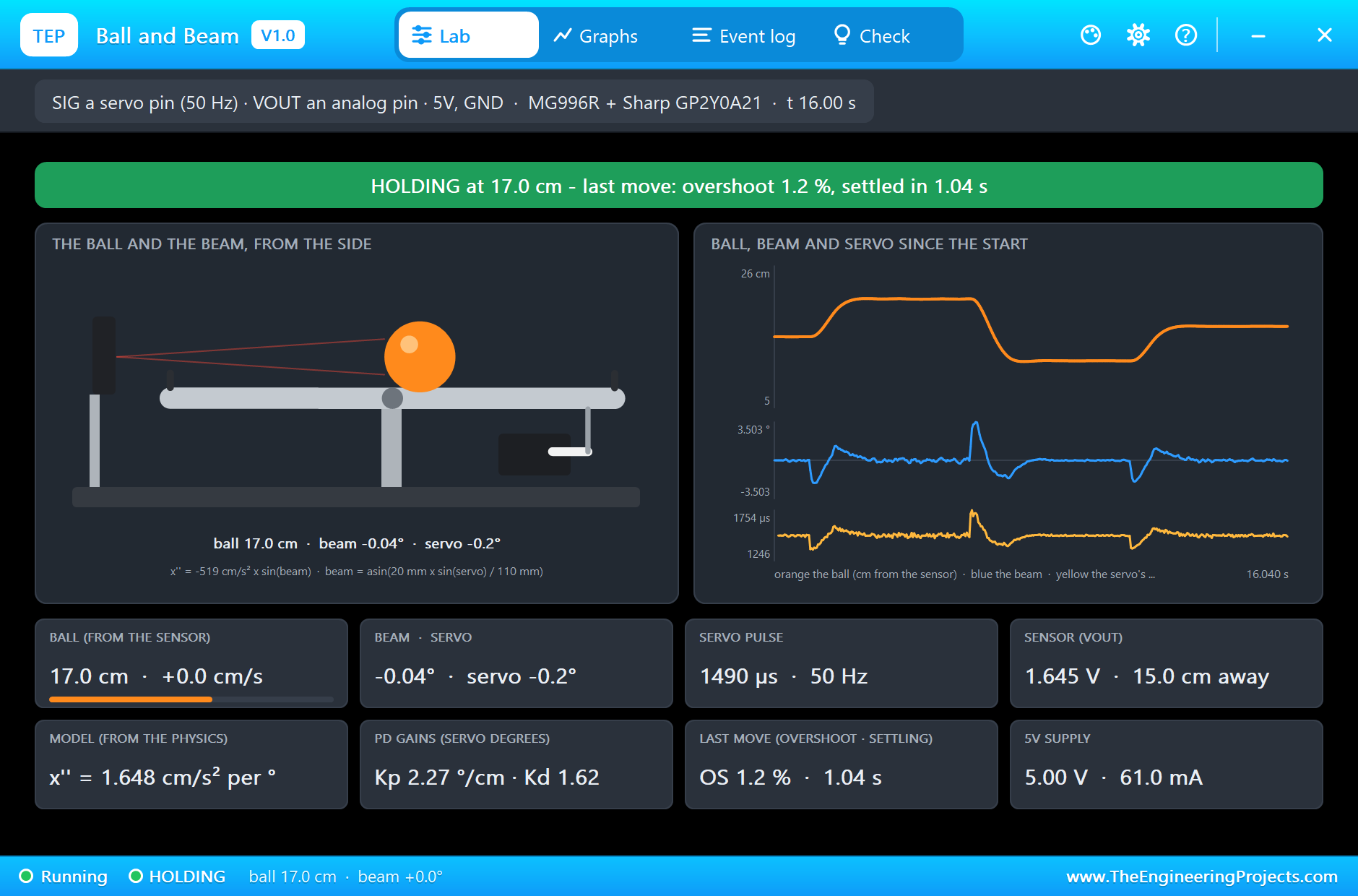
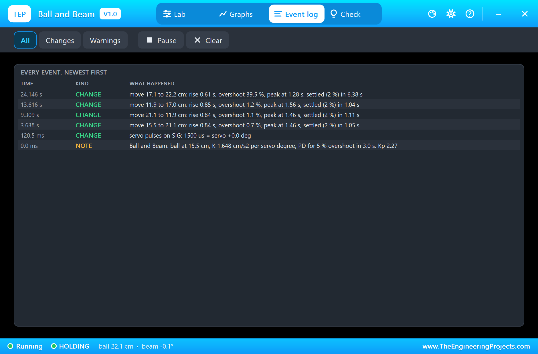
The pop-up measures each move from rest to rest. The move from 15.5 to 21.1 cm rises from 10 % to 90 % of the way in 0.84 s, overshoots by 0.7 %, peaks at 1.46 s and settles within 2 % in 1.05 s. From 21.1 to 11.9 cm: 0.84 s, 1.1 %, 1.46 s and 1.11 s. From 11.9 to 17.0 cm: 0.85 s, 1.2 %, 1.56 s and 1.04 s. The ball never touched an end stop. The design asked for 5 % overshoot and 3 s, and an ideal PD controller with these gains would give exactly that: our offline check of the same equations gives 4.5 % and 2.7 s. The real loop is not ideal. It sees the ball only every 38 ms, through a filter, and drives a servo that needs time to turn, and in this lab those differences make the moves faster and better damped than the design; the same offline check with the sensor, the filter and the servo included gives 0.5 % and 1.3 s, close to what Proteus measured. Comparing the measured moves with the design is what the pop-up is for.
Half the Derivative
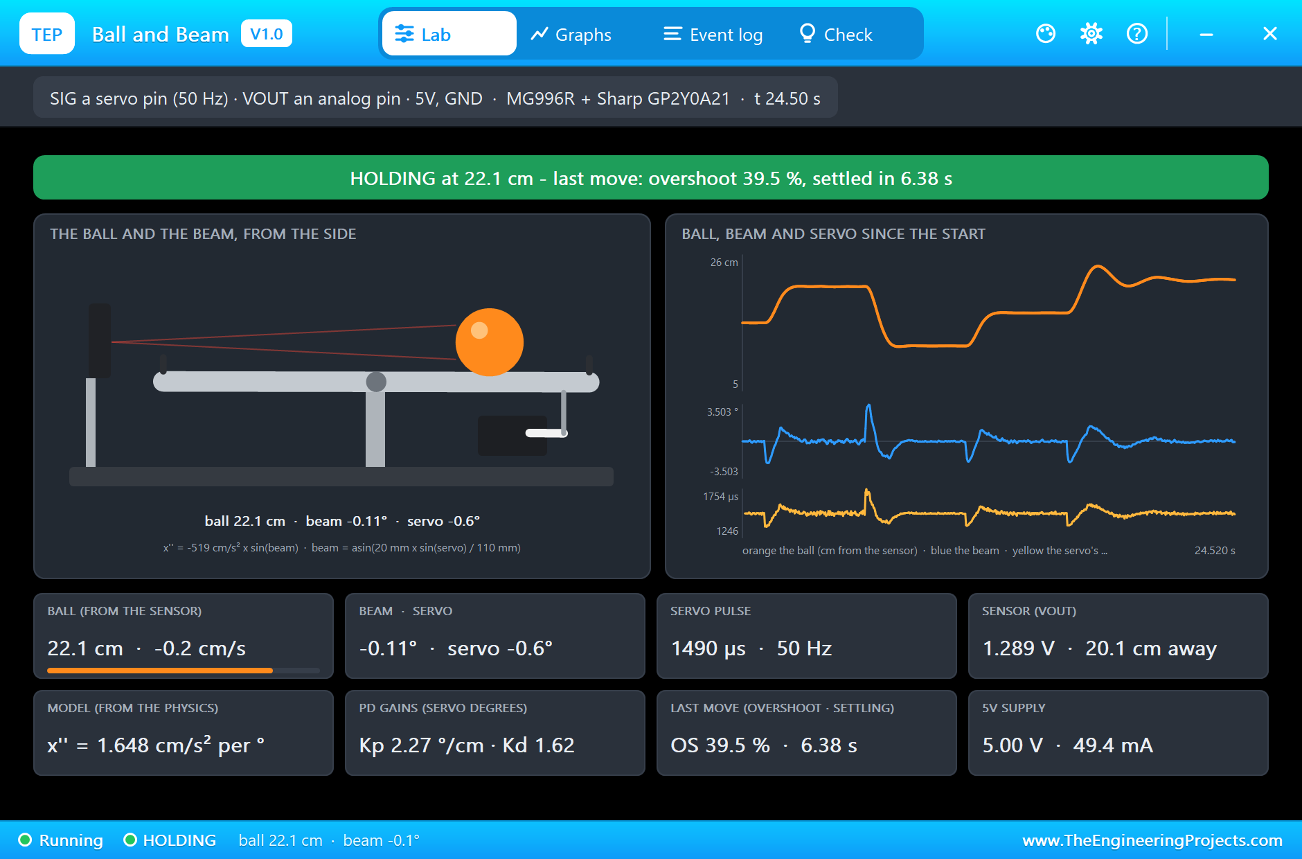
At 16 s the sketch halves the derivative and moves the ball from 17.1 to 22.2 cm. With half the damping the ball shoots off faster, 0.61 s from 10 % to 90 %, and overshoots by 39.5 %, peaking at 1.28 s, about 24 cm. Then it rolls back and forth around the target, and takes 6.38 s to settle within 2 %, six times longer than the full-gain moves. On the trend the difference is plain: three clean steps, then a step with a big hump and a slow wobble.
The Monitor
The UNO's monitor prints the ball, the target and the servo every half second. Its readings are the sketch's own, from the sensor: they wander by a few millimetres around the true position because of the sensor's noise and the ADC's steps, which is exactly what a real lab shows. In the half-derivative move it reads 18.3 cm at 16.5 s with the servo at -4.9 degrees, 24.2 cm at 17.5 s with the servo at +7.8 degrees as it brakes the overshoot, and 22.0 cm again by 20 s.
The Graphs, the Log and the Check Page
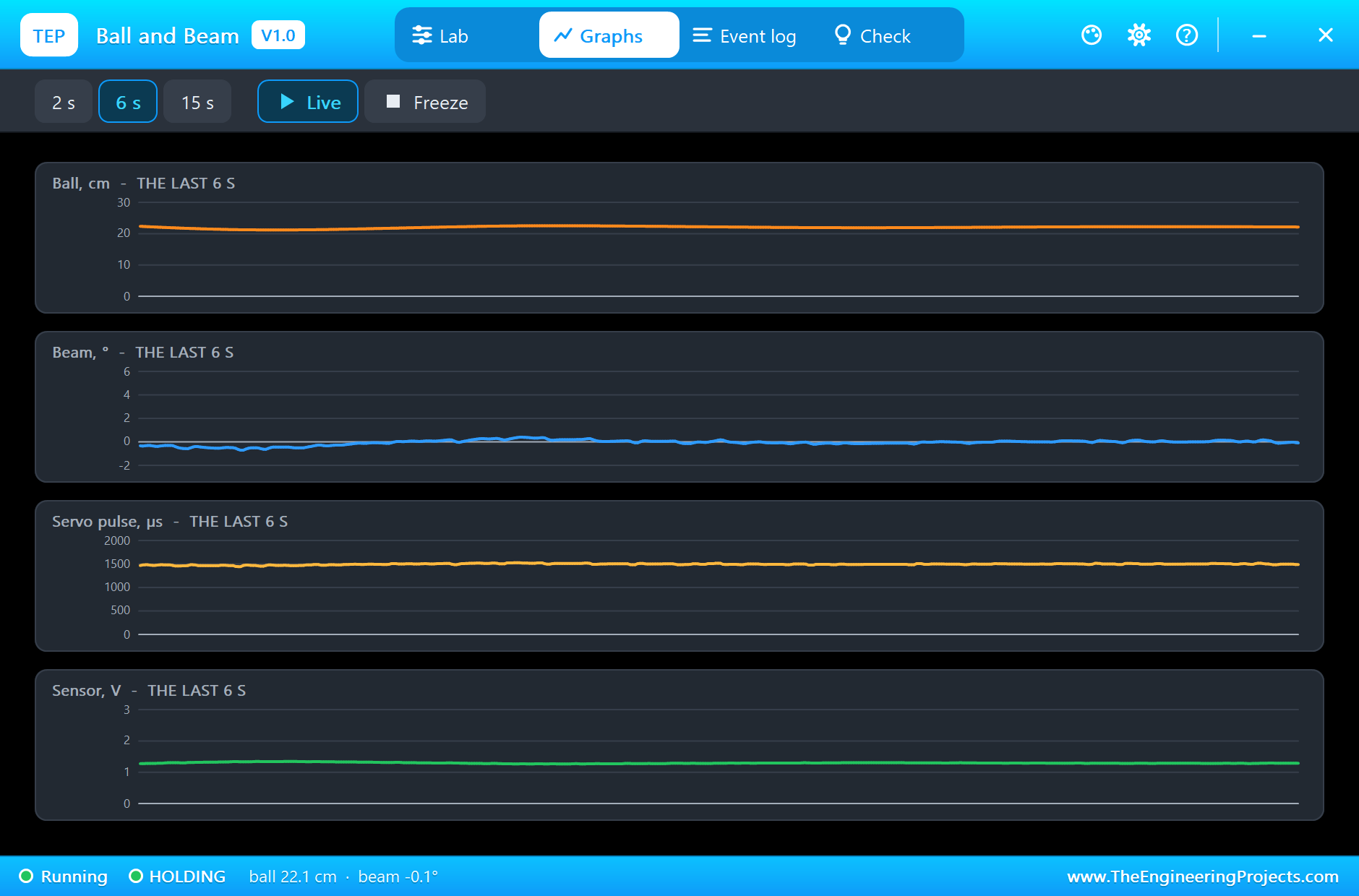
The Graphs page plots the ball, the beam, the servo pulse and the sensor voltage over the last 2, 6 or 15 simulated seconds. The Event log notes when the servo pulses started and lists every move with its rise time, overshoot, peak time and settling time.
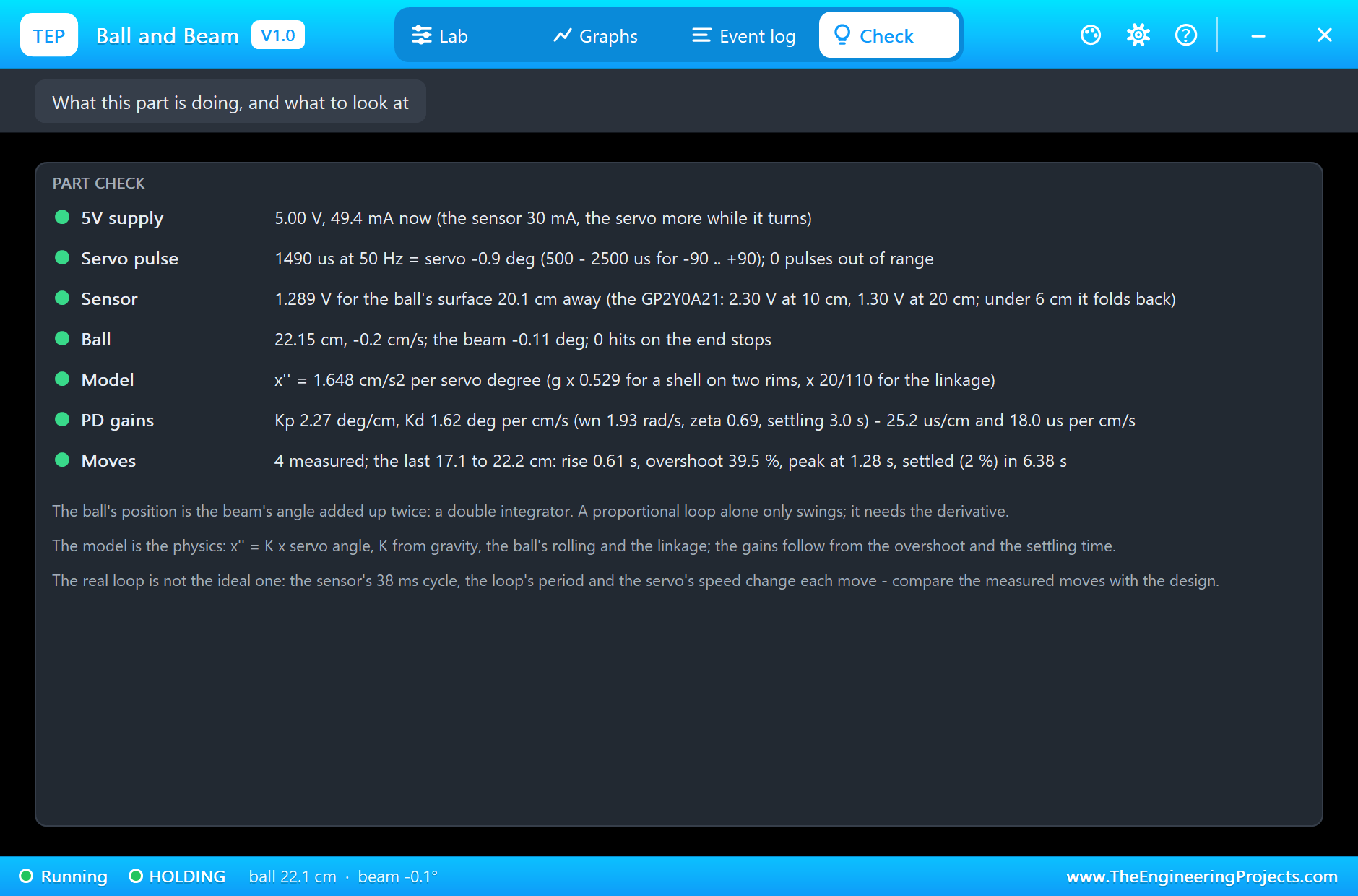
The Check page sums up the part. The 5V supply is green, with the current now; the servo pulse is 1490 µs at 50 Hz, with none out of range; the sensor reads 1.289 V for the ball's surface 20.1 cm away; the ball has hit the end stops 0 times. The model and the PD gains are listed with their working, and the moves row repeats the last one.
Try It Yourself
- Set KD to 0 and watch the ball swing from end to end: a proportional loop alone cannot settle a double integrator.
- Set TSET to 1.5 s, copy the pop-up's new gains into the sketch, and see how far the real loop follows the faster design.
- Raise NOISE to 20 mV and watch the derivative turn the noise into servo jitter; then filter the speed more.
- Move the targets close to the sensor, under 10 cm, and see the sensor's fold confuse the loop.
- Add an integral term and a beam that is not quite level at 1500 µs, and watch it remove the steady error.
Ideas to Extend the Demo
- Take the target from a potentiometer, or a sine wave, and measure how well the ball follows.
- Send the ball's position to a PC and fit the double integrator from the data.
- Try a lead compensator, or a state-feedback design with an observer, and compare the moves.
- Replace the sensor with an ultrasonic or a time-of-flight sensor in your own sketch and compare the noise.
Your Own Sketches
The demo sketch is in the zip file, and you can change it in the Arduino IDE. New to Arduino? Start with our Arduino Tutorial for Beginners. Export the compiled binary, and set the UNO's PROGRAM property to the new file. Our guide on How to get the HEX file from Arduino shows you where the file ends up.
Things to Know Before Using a Real Lab
- Power the servo properly: an MG996R can draw an amp when it strains; give it its own 5 to 6 V supply with its ground joined to the Arduino's.
- Keep the ball away from the sensor: under about 6 cm the GP2Y0A21's output folds back and reads as far.
- Filter the speed: the derivative amplifies the sensor's noise; average the readings and smooth the speed.
- Level the beam first: find the pulse that holds the ball still and use it as the centre.
- Start gently: a long settling time first, then speed it up once the loop works.
Troubleshooting
- NO SIGNAL: no pulse on SIG for 60 ms; the servo holds where it is. Attach the Servo library to the pin.
- NO SUPPLY: 5V is low, so the servo and the sensor are off.
- AT THE END: the ball is against an end stop; lower the gains, or check the sign: a ball too far must lift the servo's end.
- The ball creeps: the beam is not level at the centre pulse; on this lab 1500 µs is level.
- The part is not simulated:
TEPBALLBEAM.DLLis missing from MODELS and from the project folder.
Limitations of the Simulation
- The ball never slips, and the beam does not flex.
- The servo has no gear backlash or dead band, and turns at one speed limit.
- The sensor's curve is the datasheet's for white paper; a real ball's colour and curve change it a little.
- Arduino is a name of Arduino; this library is not made or endorsed by Arduino, Sharp or Labcenter.
- Tested in Proteus 8.5 in November 2026 (the demo as shipped). Proteus 7 is not supported.
So, that was all about the Ball and Beam PID Control Lab Library for Proteus. I hope it helps you run the classic unstable lab on your own PC: the model from the physics, a designed PD loop, the ball rolling to its spot, and what happens when the derivative is taken away. If you have any questions, ask in the comments and I will help you out. Till the next tutorial, take care and have fun!