Hello friends, I hope you all are doing great. Today, I am going to share the new TMC2209 Stepper Driver Library for Proteus Simulation, the 46th library of our motor series. If you have searched for a Proteus simulation of the TMC2209, the quiet stepper driver module found in most new 3D printers and CNC boards, this library brings the module itself into Proteus: STEP and DIR from your Arduino, the microsteps set by MS1 and MS2, the current set by VREF, and two coil currents you can watch following their sine and cosine.
TMC2209 Stepper Driver Library for Proteus Simulation
Latest version: V1.0 (November 2026, this tutorial)
Other motor drivers: L298 · L9110S · TB6612FNG · BTS7960 · A4988 / DRV8825 · 28BYJ-48 + ULN2003 · PCA9685 Servo · Relay Module · 30A Brushless ESC · TB6600 Stepper Driver · 60A Brushed ESC · DRV2605L Haptic Driver · ZS-X11H BLDC Driver · SimpleFOC Mini Driver · AC Dimmer Module · DRV8833 Motor Driver · L293D Motor Shield
Motors: SG90 Servo · TT Gear Motor · 28BYJ-48 Stepper · NEMA 17 Stepper · MG996R Servo · N20 Encoder Motor · JGA25-370 Encoder Motor · FS90R 360 Servo · 130 DC Motor · A2212 Brushless · X27.168 Gauge · Analog Panel Meter · DC Tachogenerator · LM393 Speed Sensor · MG90S Servo · DS3218 Servo · L12 Linear Servo · JGB37-520 Motor · RS-775 Motor · JGY-370 Worm Motor · 12V Linear Actuator · Coin Vibration Motor · Mini Submersible Water Pump · 12V Peristaltic Pump · 4-Pin PC Fan · 12V Push-Pull Solenoid · NEMA 23 Stepper Motor · Micro Linear Stepper · TYJ50 Synchronous Motor · Quartz Clock Movement · Air-Core Gauge · Electromechanical Counter · Split-Flap Display · Electric Bell · Wind Turbine · 8520 Coreless Motor · Car Wiper Motor · Car Door Lock Actuator · 12V Solenoid Water Valve · 12V Holding Electromagnet · Mini Air Pump · Planetary Gear Motor · 540 RC Motor · LRA Vibration Motor · 42BLF Hall BLDC Motor · 2204 Gimbal Motor · 120mm 230V AC Fan · NEMA 17 Closed-Loop Stepper · NEMA 17 Linear Stage · Pan-Tilt Bracket · 4-DOF Robot Arm
Helping Tools
- Serial Monitor Advance: a serial terminal window for the UART of your board
- Serial Monitor Expert: the serial monitor with extra debugging tools
- LCD Library for Proteus V3.0: 16x2, 20x4 and I2C LCDs to show your readings
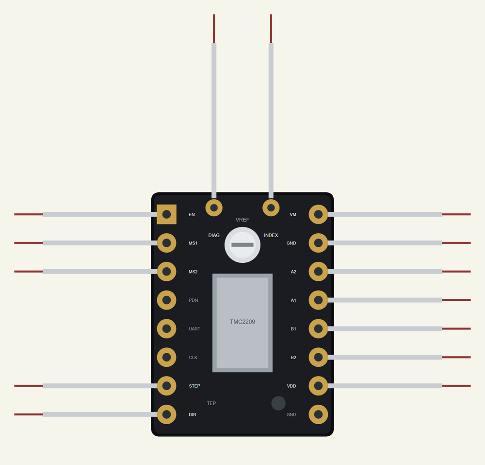
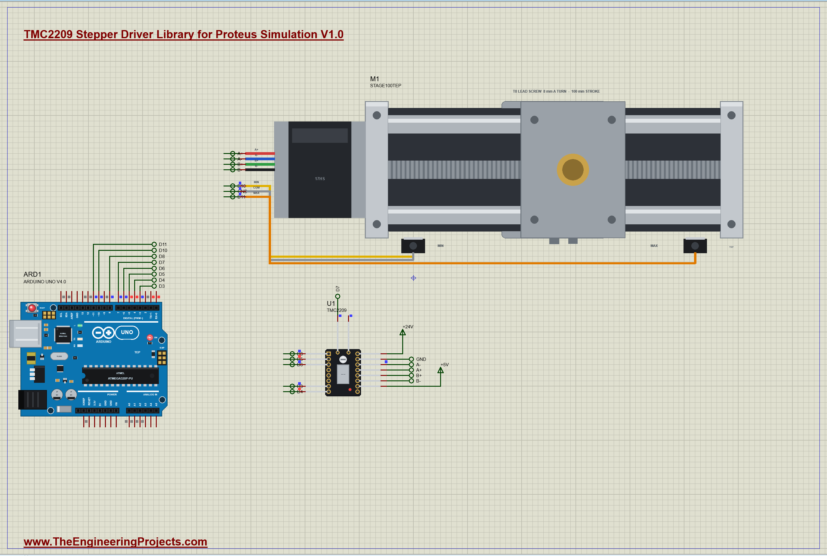
The module is drawn at its true size, the small black StepStick board with the chip's thermal pad, the VREF trimmer, its two rows of pins and the DIAG and INDEX pins on top. The simulation model drives the motor's two coils through four half-bridges with a current loop on each coil, exactly the job the real chip does, so the current reaches the motor only as fast as the supply voltage and the coil can allow. In the demo an Arduino moves our 100 mm linear stage the same 20 mm at 1/8, 1/16, 1/32 and 1/64 microsteps, then switches the driver off and on.
NOTICE: Our team has put a lot of effort into these small parts: the bodies, the animation and the pop-ups are all our own design, and you get them free. Your feedback is the fuel that keeps us going, so please tell us what you think in the comments below or in the Motor Driver board of our forum. And if our free libraries help you, you can buy us a coffee. So, let's get started with the TMC2209 Stepper Driver Library for Proteus Simulation:
What is the TMC2209 Stepper Driver?
A stepper motor has two coils, and it moves when the currents in them change in the right order. A stepper driver does that work for the microcontroller: the Arduino gives it one pulse on STEP for every step and a level on DIR for the direction, and the driver sets the two coil currents. The TMC2209 is a two-coil driver chip for motors up to 2 A RMS, sold on small plug-in modules in the StepStick format, the same footprint as the older A4988 and DRV8825 boards, so it drops into the same sockets on printer and CNC boards.
It became popular because it is quiet. Older drivers chop the coil current hard and the motor sings at every speed; the TMC2209's StealthChop2 mode shapes the voltage so smoothly that a printer's motors are almost silent. It also interpolates every input step to 256 microsteps at the motor, which its maker calls MicroPlyer, so even 1/8 or 1/16 steps from the Arduino give a smooth motion.
| The TMC2209 module (the StepStick class) | |
|---|---|
| Motor supply (VM) | 4.75 to 28 V on this module |
| Logic supply (VDD) | 3.3 or 5 V |
| Current | 2 A RMS, 2.8 A peak a coil; 0.17 ohm switches |
| Microsteps | 8, 16, 32 or 64 by MS1 / MS2, interpolated to 256 at the motor |
| Current setting | VREF on the trimmer: I peak = VREF in volts (0.11 ohm sense resistors) |
| Inputs / outputs | STEP, DIR, EN (low enables), MS1, MS2; DIAG and INDEX out |
| Board | 15.24 x 20.32 mm, two 8-pin rows on a 0.1 inch pitch |
How a Stepper Driver Controls the Coil Current
A stepper's torque comes from current, not voltage, so a stepper driver is really two current regulators. For each coil the TMC2209 has an H-bridge of four switches and a sense resistor that measures the current. Many thousand times a second it compares the measured current with the current it wants and switches the bridge to push the current up or let it fall. The supply is usually far higher than the coil needs at rest, 24 V for a 1.5 ohm coil, and that extra voltage is what lets the current change quickly at speed.
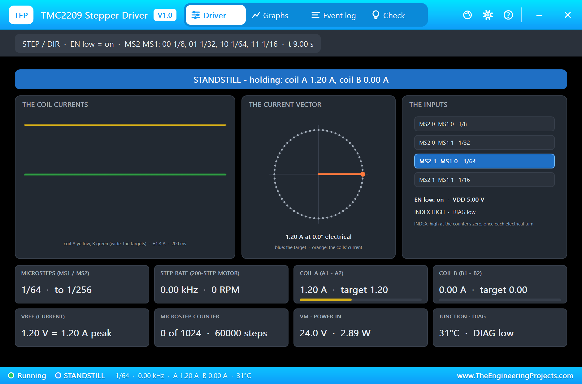
The current each coil wants comes from a table. The driver keeps a counter of 1024 microsteps for one electrical turn, four full steps, and sets coil A to the cosine of that angle and coil B to its sine, both scaled to the peak current. Every STEP pulse moves the counter, up or down by DIR: by 32 at 1/8 microsteps, by 16 at 1/16, by 8 at 1/32 and by 4 at 1/64. The two currents together form a vector of constant length that turns with the counter, and the rotor's 50 teeth follow it. At the counter's zero, coil A at its full positive current and coil B at zero, the INDEX output goes high.
Our simulation model does the same with averaged half-bridges: each coil output is a switch pair whose average voltage follows a fast current loop, 1 kHz wide, which tracks the cosine and sine targets. The motor at the other end is a real load with resistance, inductance and back-EMF, so you see what a real driver shows on an oscilloscope: the current follows its target closely at low speed and starts to lag when the back-EMF grows.
Microsteps, MS1 / MS2 and VREF
In its standalone mode, without the UART, the TMC2209 reads its microstep setting from two pins. The table is not in the order you might expect, so it is worth keeping beside your sketch:
| MS2 | MS1 | Microsteps | Pulses a turn (200-step motor) |
|---|---|---|---|
| 0 | 0 | 1/8 | 1600 |
| 0 | 1 | 1/32 | 6400 |
| 1 | 0 | 1/64 | 12800 |
| 1 | 1 | 1/16 | 3200 |
The current is set with the small trimmer. On the common module the sense resistors are 0.11 ohm, and the peak coil current in amperes is simply the voltage on VREF: 1.2 V, the usual factory setting, gives 1.2 A peak, about 0.85 A RMS. Measure VREF between the trimmer and GND and turn it to the motor's rating; in our library the VREF property plays the trimmer. EN must be low for the driver to work: high opens all the switches and the motor turns freely.
Features of the TMC2209 Stepper Driver Library for Proteus Simulation
- The module at true scale: the 15.24 x 20.32 mm black board with the thermal pad, the VREF trimmer, the two pin rows and DIAG and INDEX on top; its LED lights when VDD is on.
- STEP / DIR with microsteps: 1/8, 1/16, 1/32 or 1/64 from MS1 and MS2, with the TMC2209's own table; a 1024-microstep counter for each electrical turn; EN low enables.
- Real current control: four averaged half-bridges with 0.17 ohm switches and a current loop for each coil, so the current follows its target only as far as the supply and the motor allow.
- VREF: the peak current in amperes, from 0.2 to 2.2 V.
- Protection: over-temperature (a warning at 120 C, off at 143 C) and the short protection, with DIAG high; INDEX high at the counter's zero.
- A pop-up: the two coil currents against their targets, the current vector on its microstep circle, the inputs with the MS1 / MS2 table lit, eight live values, graphs, an event log and a check page.
- A complete package: about 1.2 MB with the library, our Arduino UNO V4.0 and the demo, without the source code of the model.
The TMC2209 in Proteus
The device is TMC2209TEP in TEPTMC2209.LIB, under Electromechanical > Motor Drivers, with the prefix U and the mixed model TEPTMC2209.DLL. Search TMC2209 in Pick Devices. The pins follow the real module: EN, MS1, MS2, STEP and DIR on the left; VM, GND, A2, A1, B1, B2 and VDD on the right; DIAG and INDEX on top. PDN, UART, CLK and the second GND are drawn as pads only. Its one property is VREF, 1.2 V by default.
Download TMC2209 Stepper Driver Library for Proteus Simulation
Click the button below to download TMC2209-Stepper-Driver-Library-for-Proteus-v1.0.zip (about 1.2 MB, without the source code of the models):
TMC2209 Stepper Driver Library for Proteus V1.0- README.txt: installation, the demo, the wiring, troubleshooting and the limits of the simulation.
- Proteus Library Files:
TEPTMC2209.LIBandArduinoV4TEP.LIB. - Proteus Model Files:
TEPTMC2209.DLLandTEPARDUINO.DLL. - Arduino Code: the demo sketch.
- Proteus Simulation: the demo project, its HEX file and copies of the DLLs.
No Proteus yet? Read How to Download and Install Proteus 7 and 8. New to libraries? Follow How to Install a New Library in Proteus.
How to Install TMC2209 Stepper Driver Library for Proteus Simulation
- Close Proteus and extract the whole zip file, for example to your Desktop.
- Copy the files from Proteus Library Files into the LIBRARY folder of Proteus.
- Copy the files from Proteus Model Files into the MODELS folder.
- Delete
TEPTMC2209.IDXfrom the LIBRARY folder if it is there. - The demo's load is our separate NEMA 17 Linear Stage Library for Proteus Simulation: install its LIB and DLL too.
- Start Proteus, press P and search for TMC2209.
Proteus Simulation of the TMC2209 with Arduino
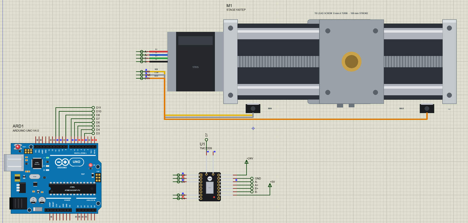
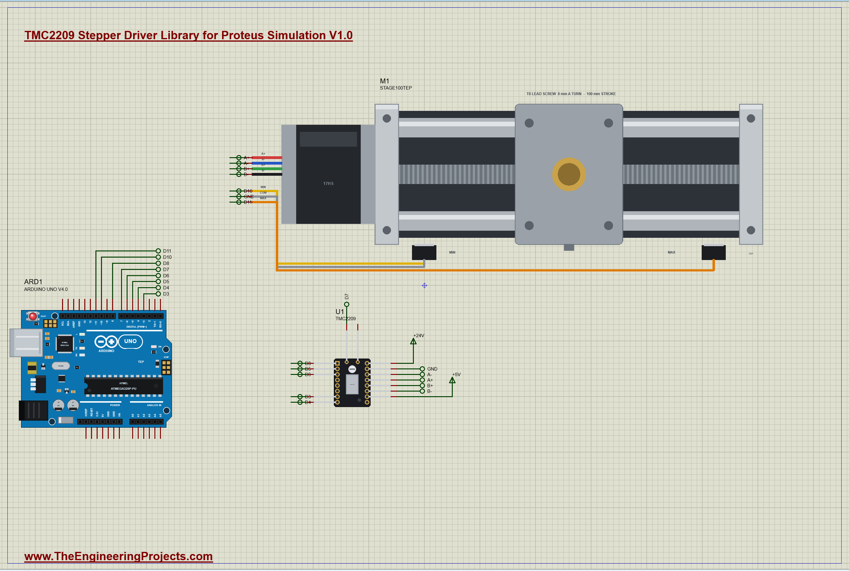
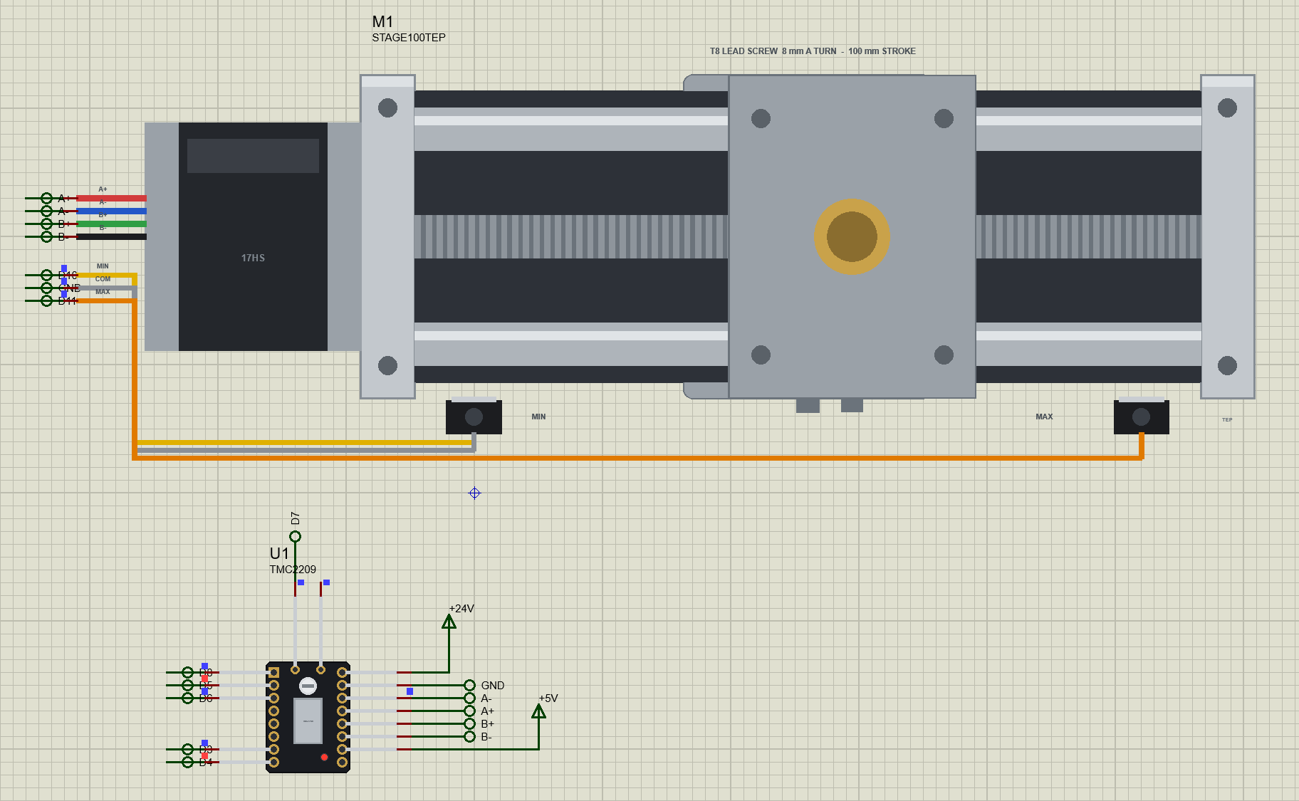
The demo has our Arduino UNO Library for Proteus V4.0 with its built-in monitor, the same window as our TEP Serial Monitor Advance for Proteus. U1 is the TMC2209 with VM on 24 V and VDD on 5 V. The UNO gives it STEP on D3, DIR on D4, EN on D8, MS1 on D5 and MS2 on D6, and DIAG comes back to D7. The load, M1, is the 100 mm stage from our separate NEMA 17 Linear Stage library (TEPLINSTAGE.LIB and TEPLINSTAGE.DLL), so install it first: A1 and A2 drive its coil A, B1 and B2 its coil B. The carriage starts in the middle of its travel, at 50 mm, so the demo does not need to home it. Open TMC2209-STAGE100-ArduinoUnoV4.pdsprj.
The Sketch
The sketch sets MS1 and MS2 from the TMC2209's table before every move:
void setMicrosteps(int m) {                                             // MS2 MS1: 00 1/8, 01 1/32, 10 1/64, 11 1/16
  mres = m;
  digitalWrite(MS1_PIN, (m == 32 || m == 16) ? HIGH : LOW);
  digitalWrite(MS2_PIN, (m == 64 || m == 16) ? HIGH : LOW);
}
With 200 full steps a turn and an 8 mm lead, a millimetre takes 25 full steps, so the pulses a millimetre are 25 times the microsteps:
long perMm() { return 25L * mres; } // 200 full steps x mres / 8 mmA move scales its speed and its ramp by the same factor, so the carriage moves the same way at every setting; only the number of pulses changes:
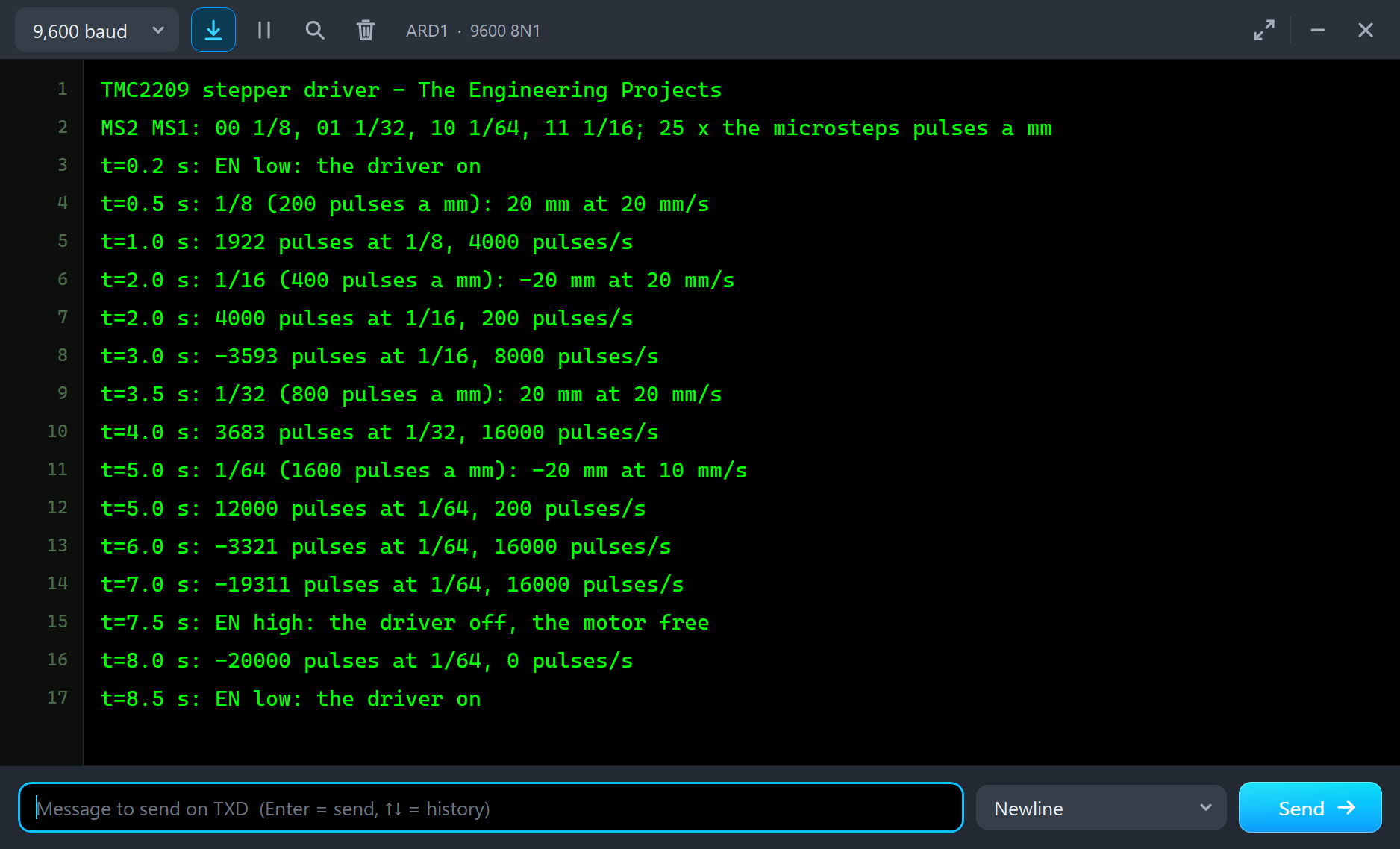
accel = 500.0 * perMm(); rateTarget = mmps * perMm(); rate = 200; setRate(rate); // (500 mm/s2 at any microstep setting)The pulses themselves come from a Timer1 interrupt, one pulse for each interrupt, as in our other stepper demos. The program enables the driver at 0.2 s, moves +20 mm at 1/8 at 0.5 s, -20 mm at 1/16 at 2 s, +20 mm at 1/32 at 3.5 s and -20 mm at 1/64 at 10 mm/s at 5 s, sets EN high at 7.5 s and low again at 8.5 s. Afterwards you can type m 16, g 10 or e 0 in the monitor.
TMC2209 Simulation Results
Open the project and press Run. The program runs about 9 simulated seconds; with both pop-ups open and the pictures being taken it took about three minutes on our PC. Click the TMC2209 to open its pop-up, and the stage for its own. Every number below comes from one simulation run, the demo exactly as it ships.
1/8 Microsteps: 200 Pulses a Millimetre
At 0.5 s the UNO sets MS1 and MS2 low, 1/8, and sends the carriage 20 mm towards MAX at 20 mm/s. At 1 s the banner reads STEPPING, 4.00 kHz at 1/8, 150 RPM for a 200-step motor, with 1.32 A in the coils. The scope shows the two currents, coil A yellow and coil B green, a quarter of a turn apart over the last 32 ms, each beside its target. The vector card shows why the motor turns: the current vector, 1.32 A long, sweeps round the circle, and the motor's field with it. Each 1/8 pulse moves the counter by 32 of its 1024, so the target jumps from one dot of the circle to the next, 32 dots an electrical turn.
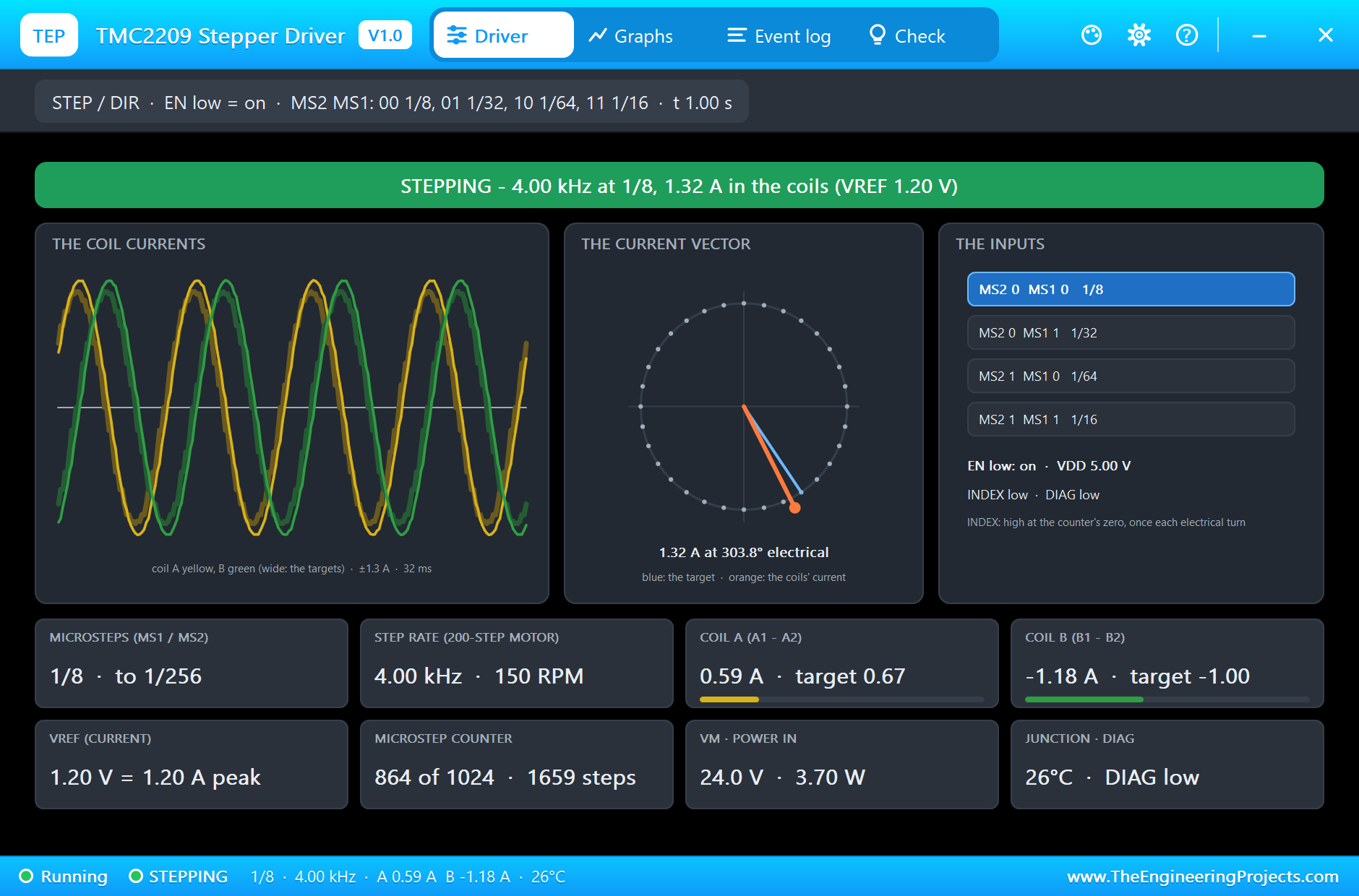
Look at the tiles too: coil A 0.59 A against a target of 0.67, coil B -1.18 A against -1.00. At 150 RPM the current loop runs a little behind its turning target, as a real chopper does when the motor's back-EMF grows. The supply gives 3.70 W from 24 V.
Standstill: the Counter at Zero and INDEX
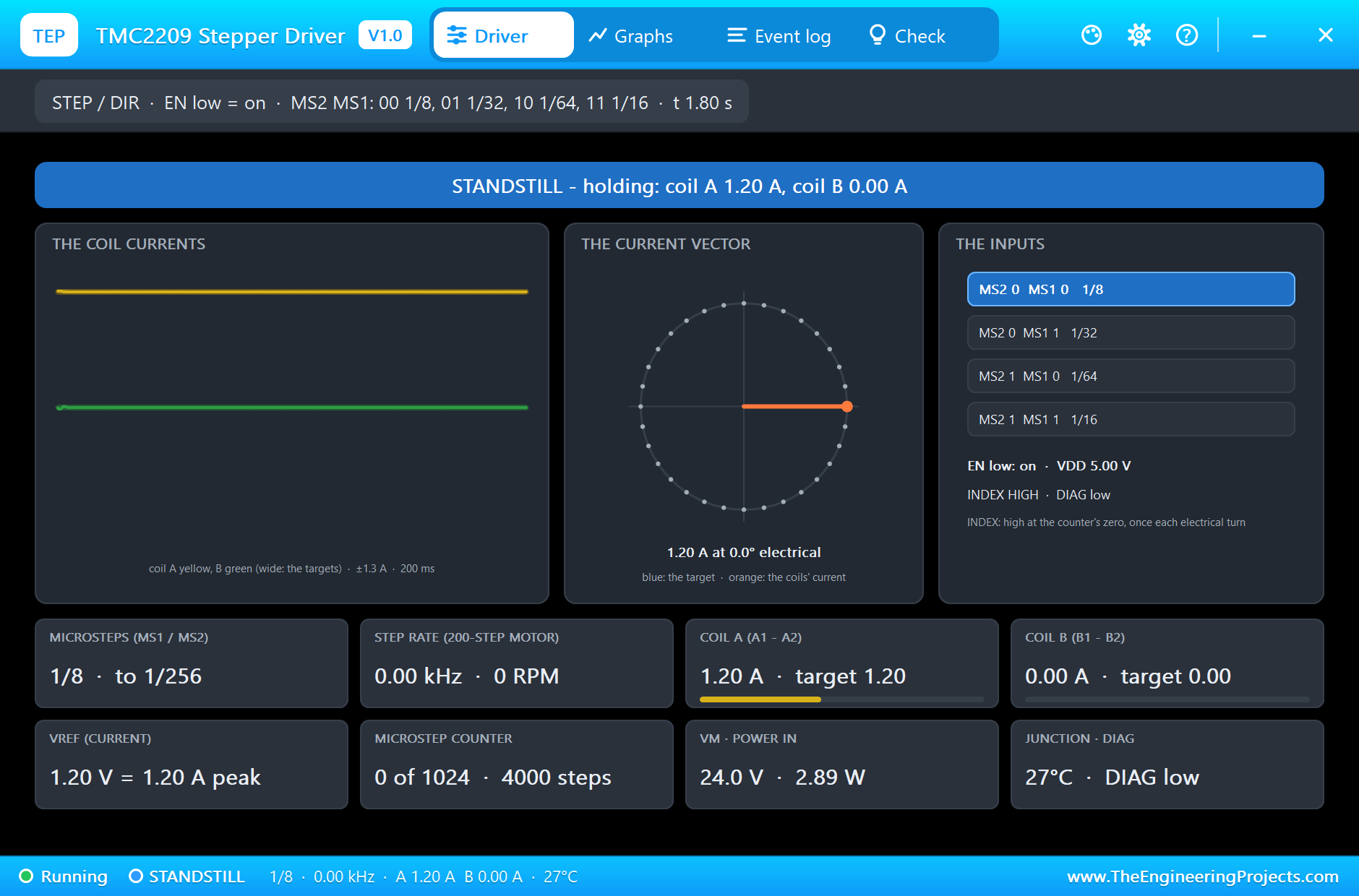
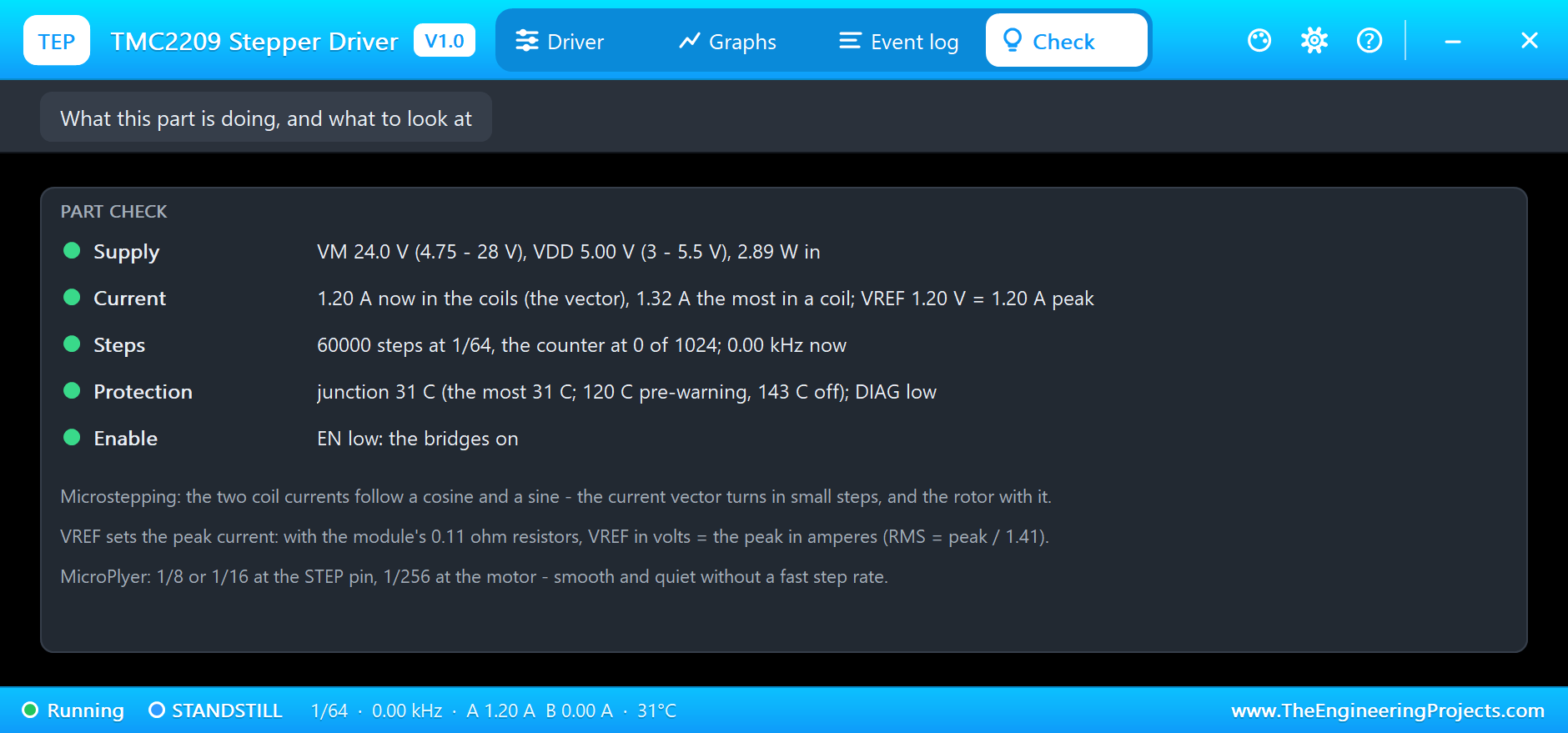
The move ends at about 1.6 s. At 1.8 s the banner turns blue, STANDSTILL, holding with coil A at 1.20 A and coil B at 0.00 A, the counter at 0 of 1024 after 4000 steps: 20 mm at 200 pulses a millimetre. With the counter at zero, the INDEX output is HIGH on the inputs card; it goes high once every electrical turn, which a controller can use to check that no pulses went missing. Holding takes 2.89 W.
1/16 and 1/32: the Same Speed, Twice the Pulses
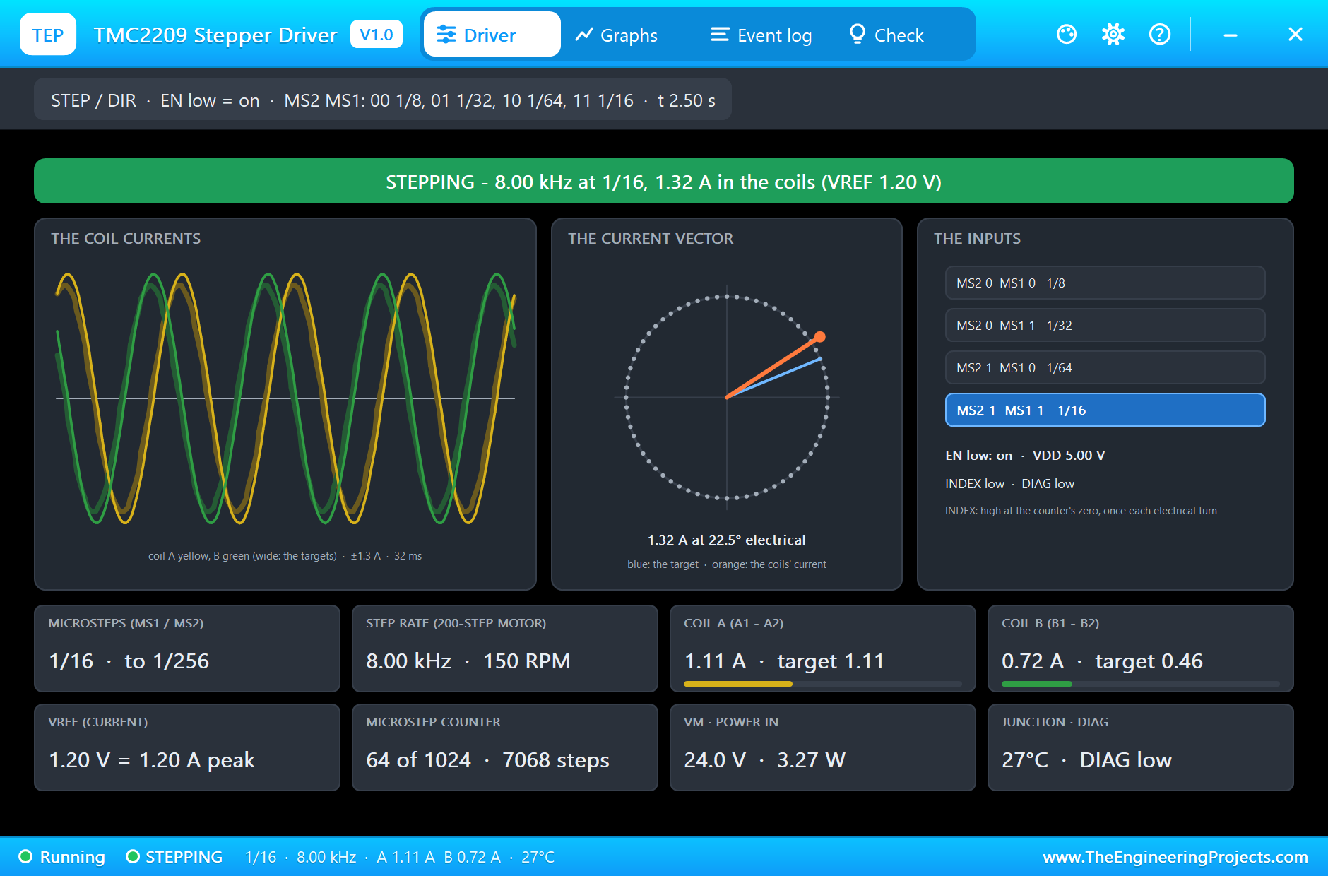
At 2 s the UNO sets both MS pins high, 1/16, and moves the carriage back 20 mm at the same 20 mm/s. At 2.5 s the step rate is 8.00 kHz, twice the rate at 1/8, and the motor still turns at 150 RPM. At 1/16 the target moves 16 counts a pulse, so the circle on the vector card has twice as many dots. Coil A follows its target exactly, 1.11 A; coil B, 0.72 A against 0.46, shows the loop catching up.
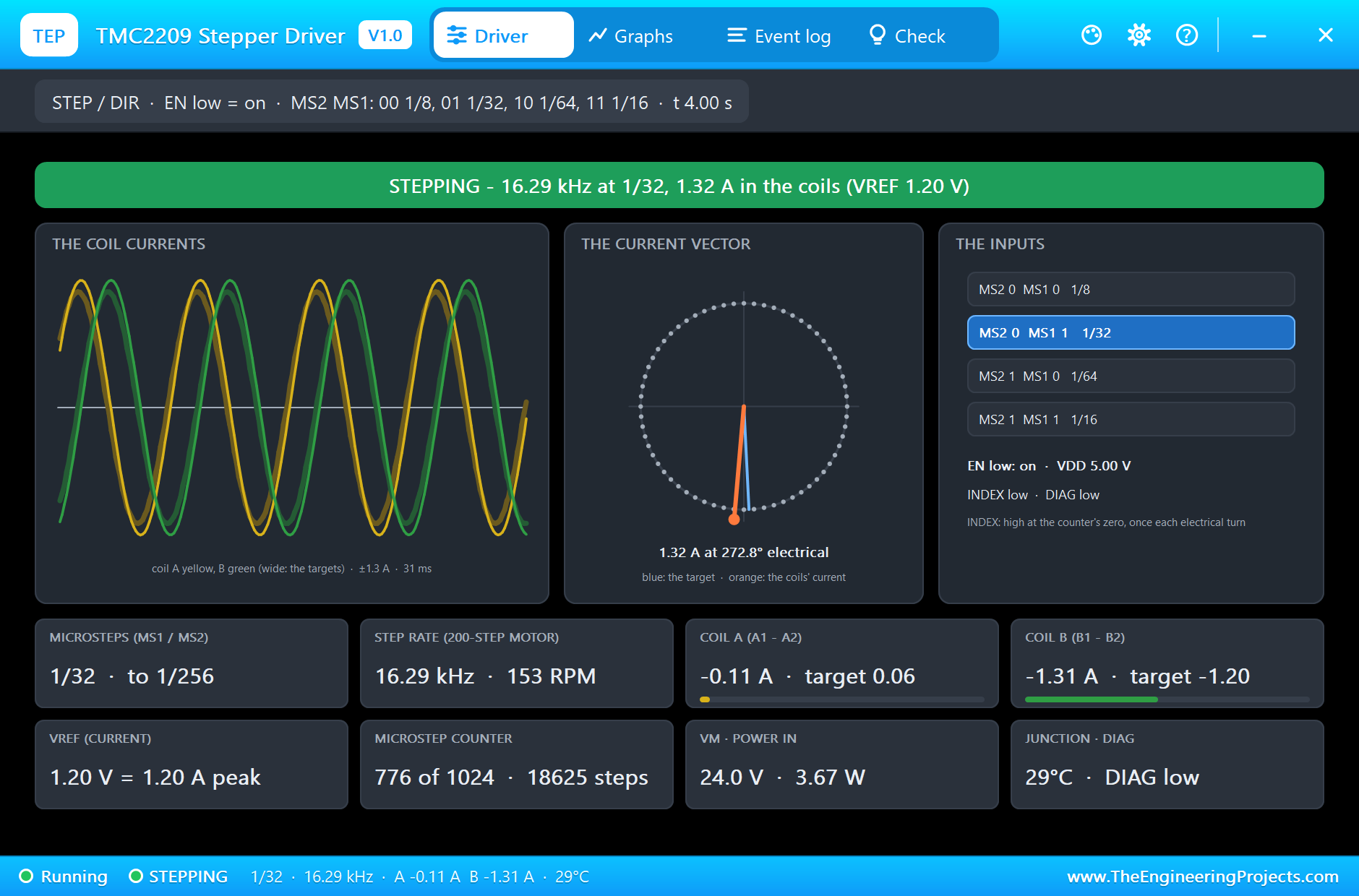
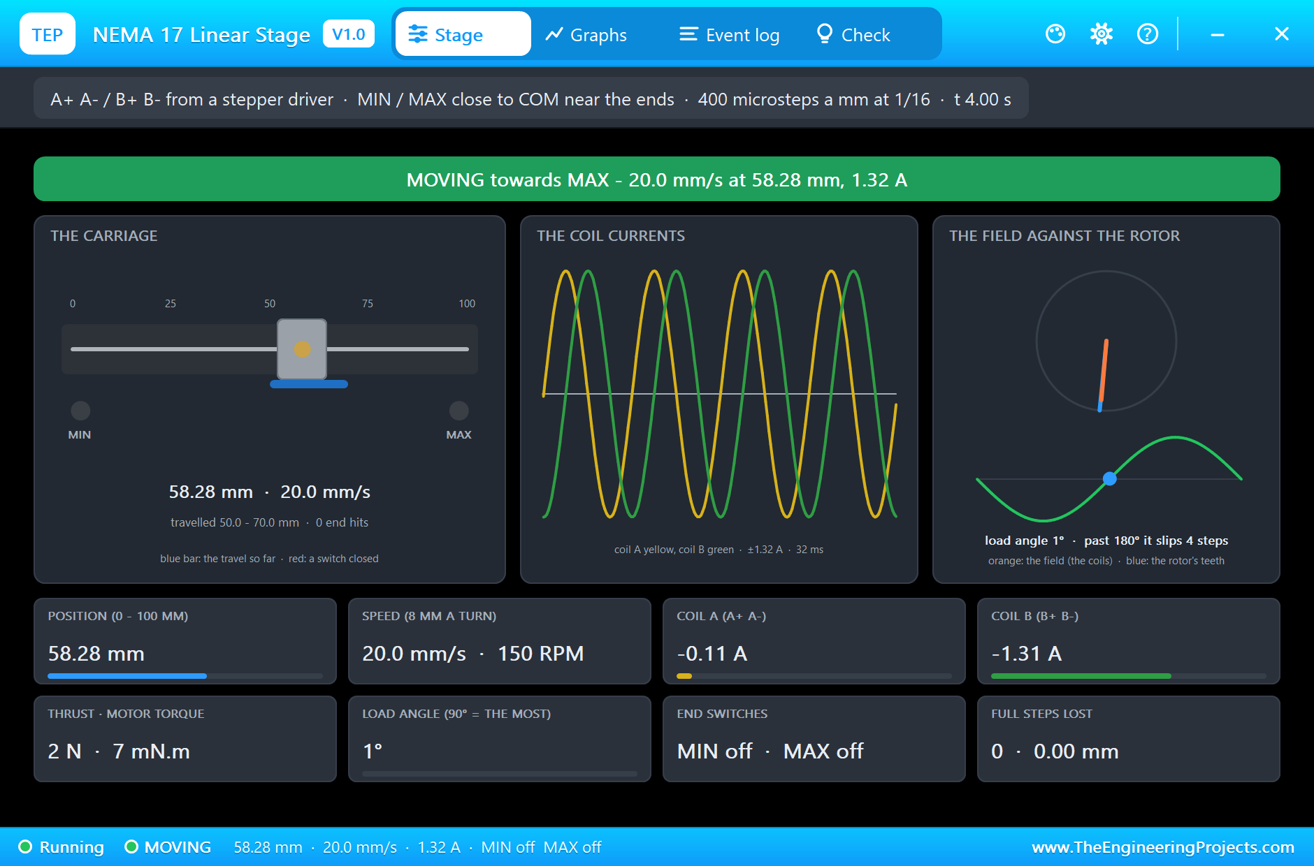
At 3.5 s it is 1/32 and 20 mm forward again. At 4 s the UNO sends 16.29 kHz, 153 RPM, and the stage's pop-up shows the carriage at 58.28 mm at 20.0 mm/s: the same point at the same speed as at 1 s, with four times the pulses. The motor cannot tell the difference; only the pulse rate and the smoothness change. Here coil B is -1.31 A against a target of -1.20, and the die has warmed to 29 C.
1/64 at 10 mm/s
At 5 s the UNO sets 1/64, 1600 pulses a millimetre. At 20 mm/s that would need 32 kHz, so the sketch runs this move at 10 mm/s to keep the UNO's pulse rate at 16 kHz: at 5.5 s, 16.10 kHz and 75 RPM with 1.25 A, coil A at -1.22 A against -1.18. At the lower speed the loop follows more closely. The die is at 30 C and the supply gives 3.41 W. This is the real cost of fine microsteps: the pulse rate climbs fast, and a small microcontroller runs out of pulses long before the motor runs out of speed.
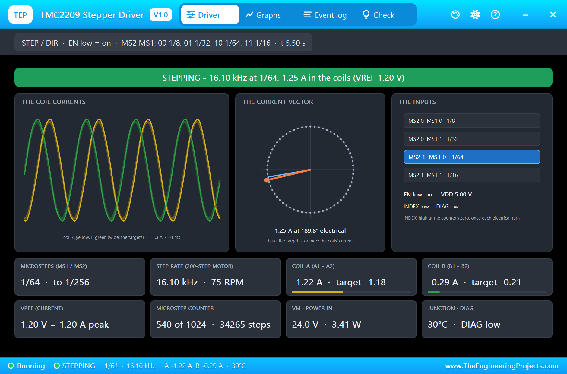
At 7.3 s the move is over and the driver holds again, the counter at 0 after 60000 steps in all: 4000, 8000, 16000 and 32000, the same 20 mm four times. The carriage is back at 50 mm, where it started. The sketch's own counter shows the trap: it adds up raw pulses, so after the four moves it reads -20000, although the carriage is home. A pulse is a different distance at each setting, so a sketch that changes the microsteps must scale its counts too.
EN High and Low
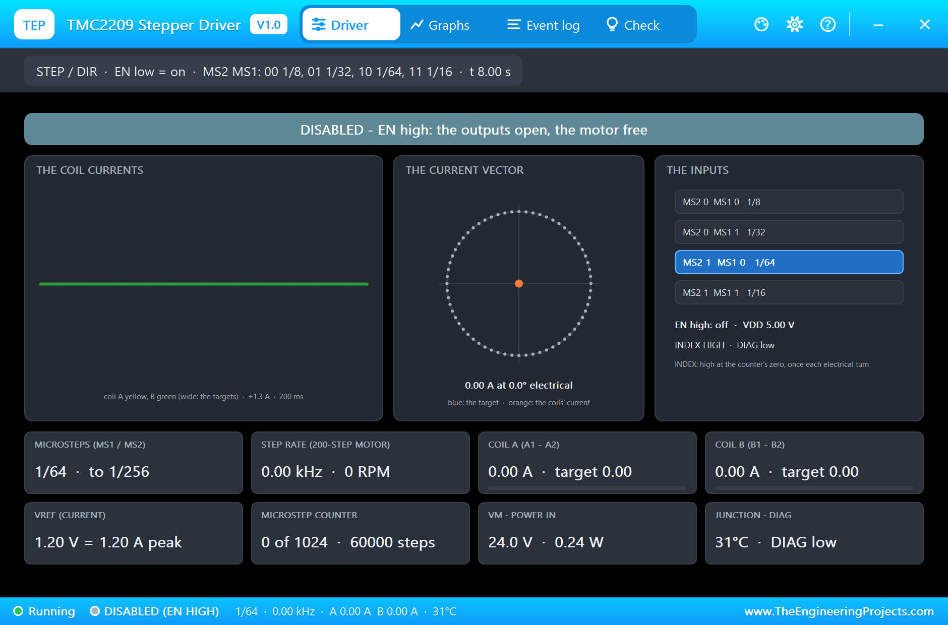
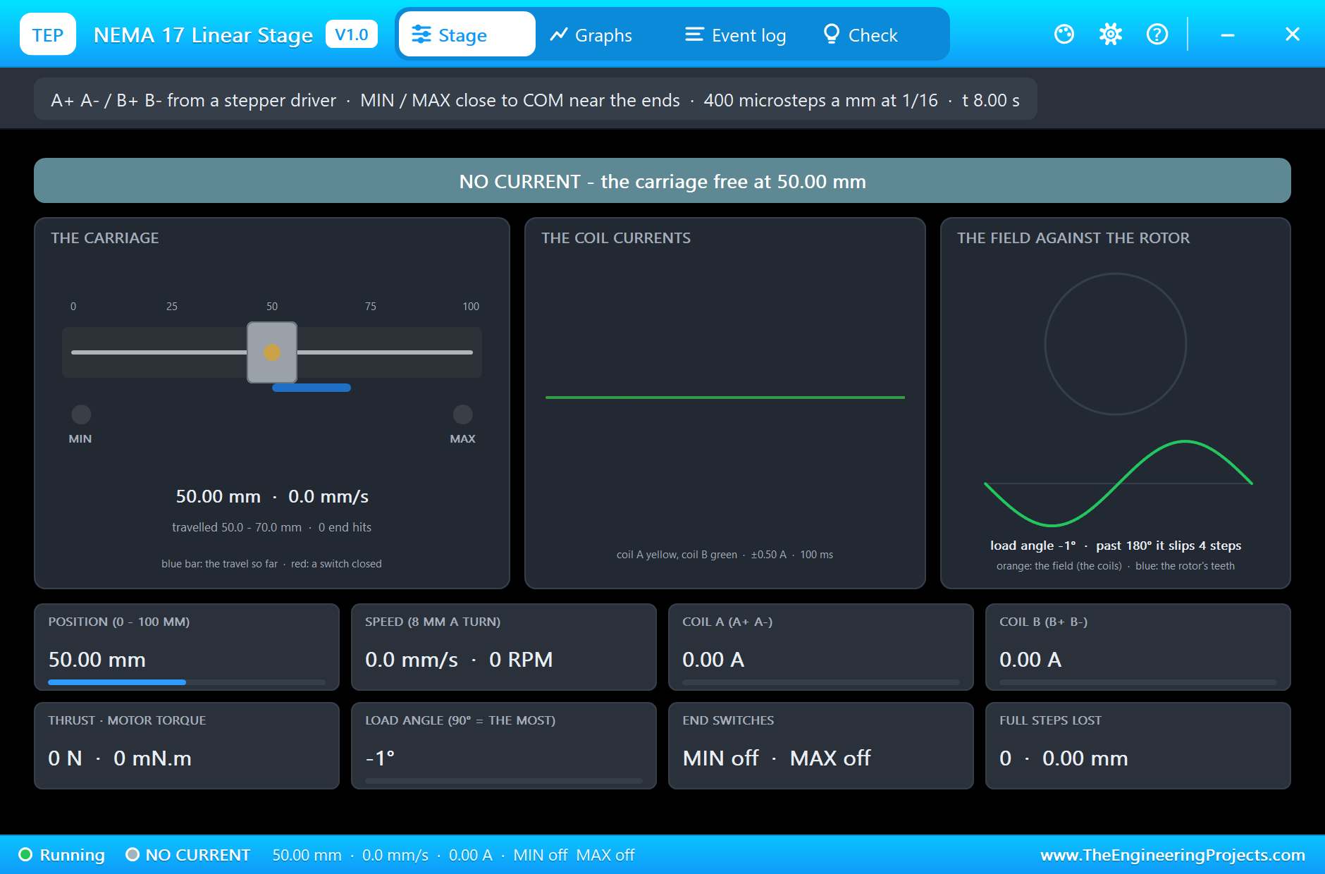
At 7.5 s the UNO sets EN high. The banner turns grey, DISABLED: all four outputs open, both coil currents 0.00 A, and the module draws 0.24 W. On the stage's pop-up the banner reads NO CURRENT: the carriage is free at 50.00 mm, and a push would move it. At 8.5 s EN goes low again and the driver holds 1.20 A on coil A, the counter still at 0: the TMC2209 keeps its counter while it is disabled.
The Graphs, the Event Log and the Check Page
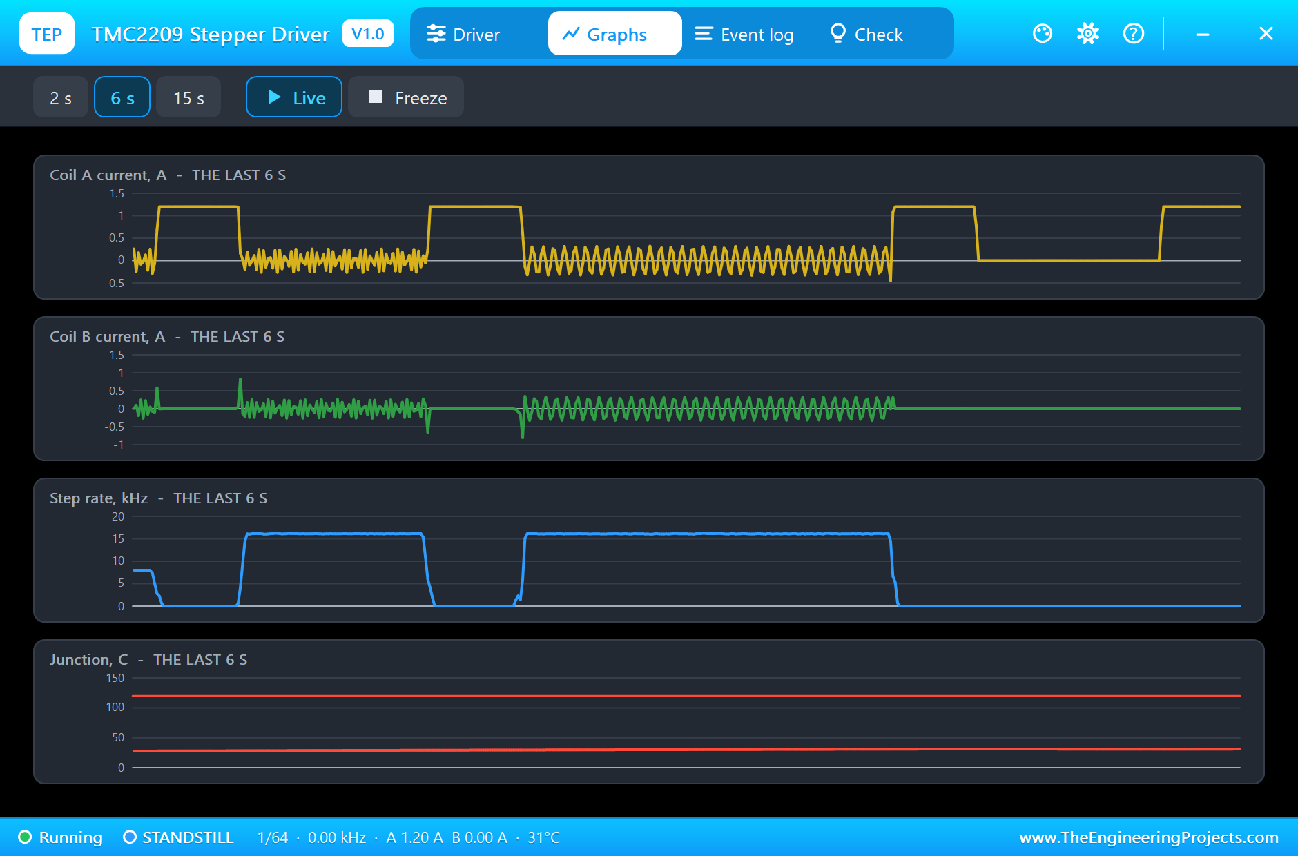
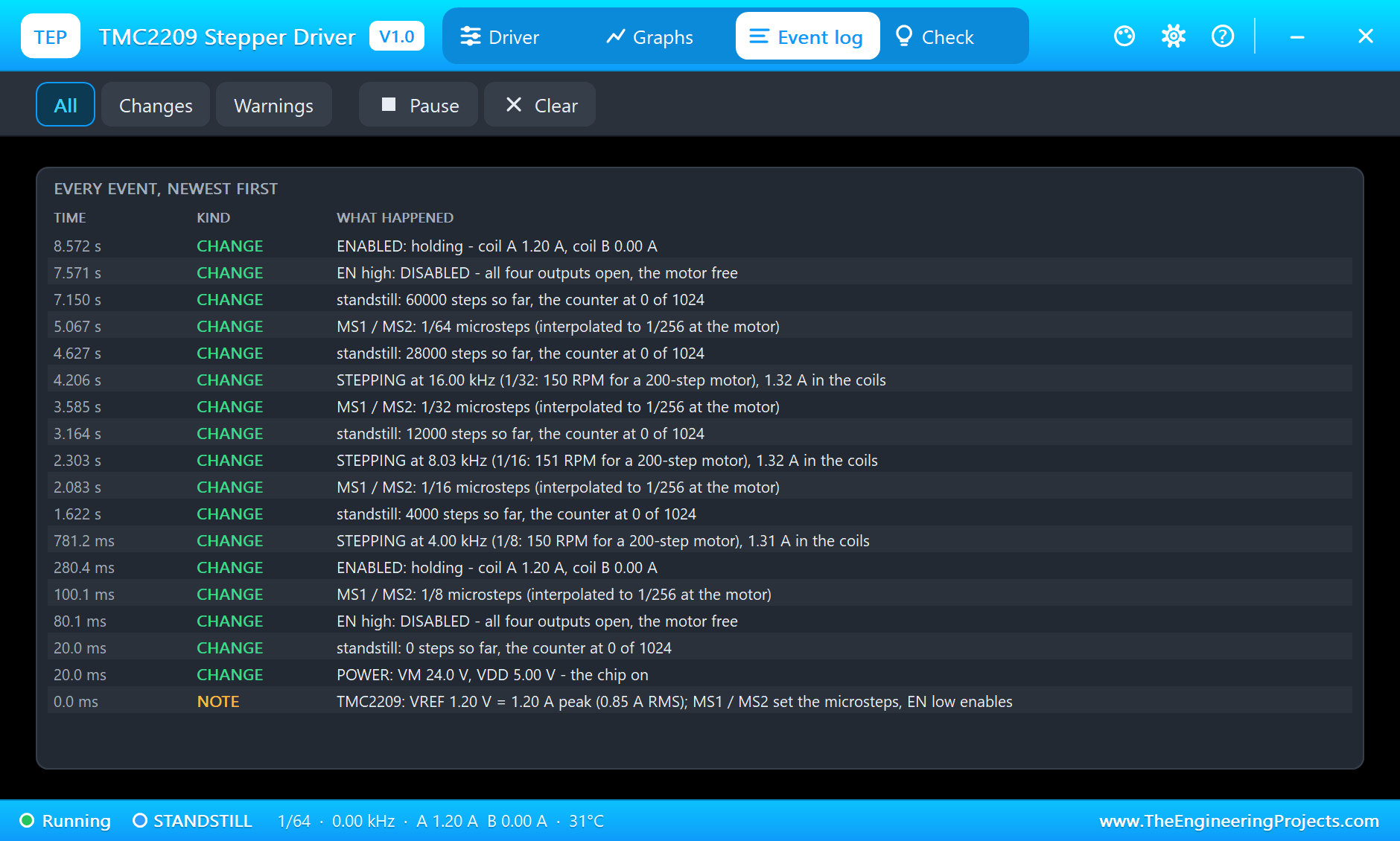
The Graphs page plots the two coil currents, the step rate and the junction temperature over the last 2, 6 or 15 simulated seconds: the moves show as bursts of sine waves, the standstills as flat lines at 1.20 A and 0 A, and EN high as both at zero. The Event log keeps every MS1 / MS2 change, each STEPPING rate and each standstill with its step count. The Check page sums up the run in green.
Try It Yourself
- Change VREF to 0.6: half the current everywhere; the holding torque and the thrust at the stage fall with it.
- Type
m 16and theng 10: 4000 pulses for 10 mm; typem 8andg -10: 2000 pulses back to the same place. - Type
e 0: EN high, the stage free;e 1holds it again. - Raise VREF to 2.2 and watch the junction climb on the Graphs page.
- Disconnect MS1: it reads low, so 1/16 becomes 1/64 and every move comes up four times short.
Ideas to Extend the Demo
- Use the INDEX output to check the step count after each move.
- Add a second TMC2209 and stage: two axes from one UNO.
- Choose the microsteps from the speed: 1/32 for slow, smooth moves and 1/8 for fast ones, scaling the counts.
Your Own Sketches
The demo sketch is in the zip file, and you can change it in the Arduino IDE. New to Arduino? Start with our Arduino Tutorial for Beginners. Export the compiled binary, and set the UNO's PROGRAM property to the new file. Our guide on How to get the HEX file from Arduino shows you where the file ends up.
Things to Know Before Using a Real TMC2209 Module
- Set VREF first: measure it between the trimmer and GND with the module powered; on the common module the volts are the peak amperes.
- Cool it: above about 1 A RMS the module needs its heatsink and some air.
- Mind the pin table: MS1 / MS2 on the TMC2209 do not follow the A4988 table; 00 is 1/8, not full steps.
- Never unplug the motor with VM on: the coil's current has nowhere to go and the driver can fail.
- Add a capacitor: 100 uF or more across VM and GND, close to the module.
Troubleshooting
- The motor does not move: EN is high, VM or VDD is missing, or STEP never changes.
- It moves the wrong distance: MS1 / MS2 do not match the microsteps the sketch assumes.
- It moves the wrong way: invert DIR in the sketch, or swap the two wires of one coil.
- DIAG high: over-temperature or a short; lower VREF and cool the module, and for a short set EN high and low again.
- The part is not simulated:
TEPTMC2209.DLLis missing from MODELS and from the project folder.
Limitations of the Simulation
- The coil currents are the averaged currents of the four half-bridges with a 1 kHz current loop, our tuning; the chopper's ripple and StealthChop's voltage mode are not modelled.
- The UART registers, StallGuard, CoolStep and the standstill current reduction are not modelled.
- The thermal figures (30 K/W, 0.5 J/K) are our estimates for the small module.
- Arduino is a name of Arduino; this library is not made or endorsed by Arduino, Labcenter or any chip or module maker.
- Tested in Proteus 8.5 in November 2026 (the demo as shipped). Proteus 7 is not supported.
So, that was all about the TMC2209 Stepper Driver Library for Proteus Simulation. I hope it helps you see in a simulation what a stepper driver really does with your pulses: the microstep counter, the two coil currents following their sine and cosine, the MS1 / MS2 table, VREF and EN, on a real lead-screw stage. If you have any questions, ask in the comments and I will help you out. Till the next tutorial, take care and have fun!