Hello friends, I hope you all are doing great. Today, I am going to share the new DC Motor Speed and Position Control Lab Library for Proteus, the second of our University Lab series. The DC servo is the workhorse of control courses: a small motor with a flywheel and an encoder, driven from a computer, on which students identify the motor with a bump test, design a PD controller for a given overshoot and peak time, and then watch the flywheel snap to an angle. The same skills drive robot joints, camera gimbals, printer heads and the feed axes of machine tools.
DC Motor Speed and Position Control Lab Library for Proteus
Latest version: V1.0 (November 2026, this tutorial)
Other component libraries: C945 Transistor · PC817 Optocoupler · Relay Module · Resistor · 5 mm LED · Designer Colour LED · Push Button · Active Buzzer · Electrolytic Capacitor · Ceramic Capacitor · Tantalum Capacitor · Film Capacitor · 1N4007 Diode · Zener Diode · Schottky Diode · Supercapacitor · Photodiode · RGB LED · Bridge Rectifier · Flashing LED · Bi-Colour LED · SMD LED · Slide Switch · Toggle Switch · Rocker Switch · Micro Limit Switch · Emergency Stop Switch · SMD Resistor · Power Resistor · Resistor Network · Potentiometer · Trimmer Potentiometer · Slide Potentiometer · NTC Thermistor · DIP Switch · Fuse · Passive Buzzer · Mini Speaker · 7-Segment Display · LED Bar Graph · IR / UV LED · Small Transistors · TIP122 Darlington · N-MOSFET · P-MOSFET · PC817 Optocoupler · Filament Bulb · Power LED · Voltage Regulator · SCR and TRIAC · Inductor · Toroid Inductor · Crystal · Temperature Control Lab · Ball and Beam · Magnetic Levitation · Rotary Pendulum · Coupled Tanks · AD8232 ECG · MyoWare EMG · GSR Sensor · MAX30205 · MCP4725 · MCP3008 · LM358 · NE555 Timer · INA128 · 74HC595
Helping Tools
- Serial Monitor Advance: a serial terminal window for the UART of your board
- Serial Monitor Expert: the serial monitor with extra debugging tools
- LCD Library for Proteus V3.0: 16x2, 20x4 and I2C LCDs to show your readings
Our library brings that lab into Proteus. It is our own servo lab, drawn at true scale: a coreless DC motor with the values of a real industrial motor, a brass flywheel on its shaft and a 100-line optical encoder under it, 400 counts per turn. The motor is a real circuit element that any driver can drive, and the encoder gives real quadrature edges that an Arduino counts in interrupts. The pop-up does the control engineer's homework live: it fits a bump test to a first-order model, turns the model into PD gains, and measures every move the flywheel makes. The demo runs a bump test, four PD moves and one move without the derivative, from an Arduino UNO through our L9110S driver.
NOTICE: Our team has put a lot of effort into these small parts: the bodies, the animation and the pop-ups are all our own design, and you get them free. Your feedback is the fuel that keeps us going, so please tell us what you think in the comments below or in the DC Servo Lab board of our forum. And if our free libraries help you, you can buy us a coffee. So, let's get started with the DC Motor Speed and Position Control Lab Library for Proteus:
What is a DC Servo Lab?
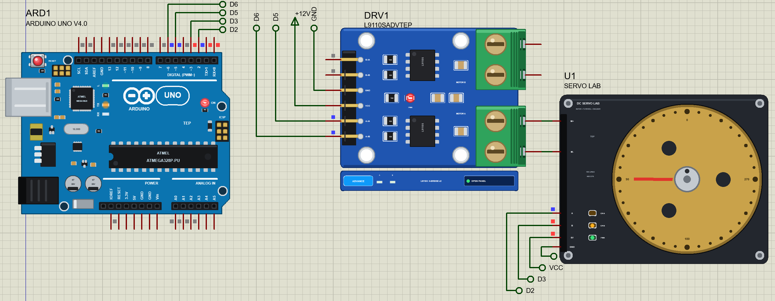
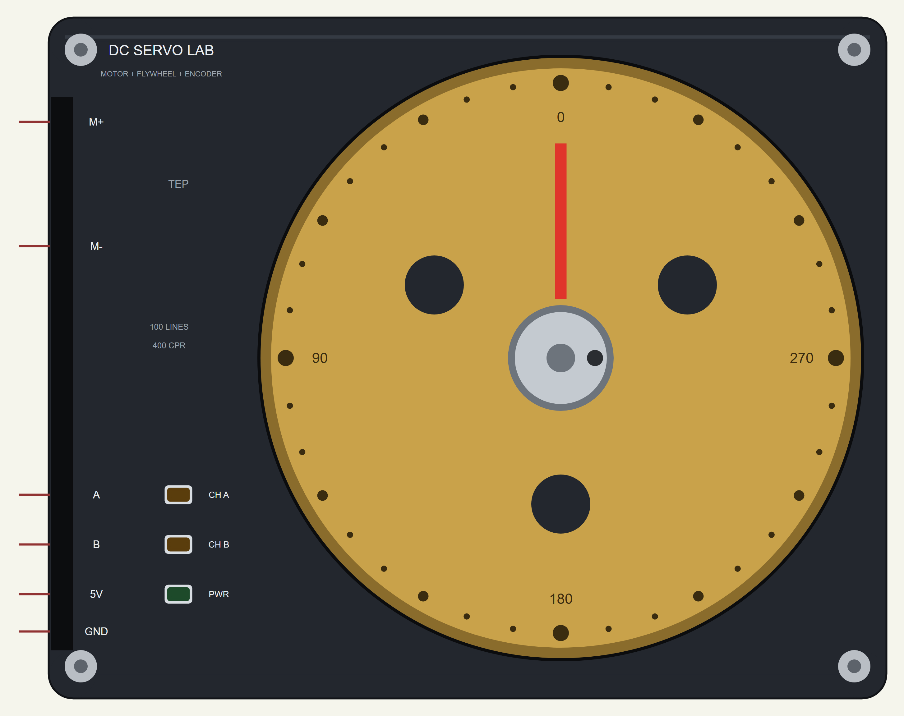
A servo is a motor that goes where it is told. The motor itself only knows voltage: more volts, more speed. To turn it into a servo you need a sensor that reports the shaft's position, here an optical encoder, and a controller, here an Arduino, that compares the position with the target and sets the voltage. A teaching servo adds a heavy flywheel so the motion is slow enough to see and the dynamics are clean: almost all the inertia is in one well-known disc. Our lab is a base 64 by 52 mm, smaller than the UNO, with the motor standing under a 46 mm brass flywheel, its scale marked every 10 degrees and a red index line, and the encoder board with its CH A, CH B and PWR LEDs.
| The servo lab | |
|---|---|
| Size | 64 x 52 mm base, 46 mm flywheel |
| Motor | coreless DC motor, the Allied Motion CL40 values (24 V winding), run here from 12 V |
| Flywheel | brass, 46 mm across, 7 mm thick: 99 g, 2.62 x 10⁻⁵ kg m² |
| Encoder | 100 lines, both edges of A and B: 400 counts per turn, 0.9° a count |
| Pins | M+ and M- from a motor driver; A and B to two interrupt pins; 5V and GND for the encoder |
| Speed at 12 V | about 2,000 RPM with no load |
The Motor
Coreless motors are the motors of choice for servo labs: the winding is a self-supporting basket of copper with no iron, so there is no cogging, the rotor is light and the torque is smooth. Our model uses the published values of the Allied Motion CL40, a 40 mm, 7 W coreless motor, in its 24 V winding. Run from 12 V it spins at about 2,000 RPM with no load and draws at most 0.77 A with the shaft held, within reach of a small driver. The torque constant and the back-EMF constant are the same number in SI units, which is what makes a DC motor so pleasant to model.
| Quantity | Value |
|---|---|
| Terminal resistance | 15.6 Ω |
| Torque constant / back-EMF constant | 57 mN m per A / 57 mV per rad/s |
| Rotor inertia | 4.0 x 10⁻⁶ kg m² |
| No load at 24 V | 3,980 RPM, 16 mA |
| Winding inductance | 2.14 mH (0.14 ms: far faster than anything here, so it is left out) |
| Friction in the model | 0.5 mN m Coulomb plus 1 x 10⁻⁶ N m s/rad viscous |
The Flywheel and the Encoder
The flywheel is a brass disc 46 mm across and 7 mm thick. Its mass is about 99 g and its inertia, half the mass times the radius squared, is 2.62 x 10⁻⁵ kg m², more than six times the rotor's. That is the point of a flywheel: the motor now drives a known load, and the motion is slow enough to see on a scope. The encoder under it has 100 slots. Its two channels, A and B, are a quarter of a slot apart, so the controller can tell the direction from which one changes first, and counting both edges of both channels gives 400 counts per turn, 0.9 degrees a count. On our lab, A leads B while the angle grows, counter-clockwise seen from above.
First Order: How the Speed Answers
Apply a voltage to a DC motor and the speed rises along an exponential to a final value. Two numbers describe it, a first-order model. The gain K is the final speed per volt, ideally one over the back-EMF constant, about 17.5 rad/s per volt for our motor. The time constant τ is how long the speed takes to cover 63 % of the way. For the motor and flywheel alone it is the resistance times the inertia divided by the square of the motor constant, about 0.14 s; the driver's own switch resistance adds to the motor's, so with a real driver it comes out longer. A model this simple is the starting point of every servo design.
The Bump Test
The way to find K and τ is a bump test. Run the motor at a steady voltage until the speed is steady, step the voltage to a new value and hold it, and record the speed. K is the change in speed divided by the change in voltage, and τ follows from the shape of the rise. Starting from a speed rather than from rest keeps the motor away from its static friction, which would bend the curve. The pop-up fits the whole record by least squares while the test runs, and draws the fitted curve over the measured one.
From Speed to Angle: PD Control
The angle is the speed added up over time, so from voltage to angle the motor is the first-order model followed by an integrator. A proportional-derivative (PD) controller sets the voltage from the position error, Kp times the error, minus Kd times the speed. With the motor's K and τ, the closed loop behaves like a mass on a spring with a damper: its natural frequency ωn and damping ζ follow from the gains, and the other way round, Kp = ωn²τ / K and Kd = (2ζωnτ - 1) / K. So a designer picks the response and computes the gains. The pop-up designs for 5 % overshoot, which needs ζ = 0.69, and the peak 0.15 s after the step, which gives ωn = 28.9 rad/s.
Why a Proportional Loop Alone Rings
Leave out the derivative and the only damping left is the motor's own back-EMF. With the same Kp, the damping ratio drops to about 0.1: the flywheel shoots past the target, swings back past it, and rings for a second before it settles. The derivative term is speed feedback, a brake that grows with the speed, and it is what turns a ringing loop into a crisp one. The demo shows both, one after the other.
Features of the DC Motor Speed and Position Control Lab Library for Proteus
- The real look, at true scale: a 64 x 52 mm base, a 46 mm brass flywheel with a scale and an index, the encoder's CH A, CH B and PWR LEDs; the flywheel turns on the sheet and blurs when it spins.
- A real motor model: the CL40's resistance, back-EMF and inertia, friction and the flywheel, as a circuit element any driver can drive.
- A real encoder: 400 counts per turn as true quadrature edges at their own times, the outputs floating without 5 V.
- Live system identification: any held voltage step is fitted to K and τ as the speed answers.
- PD gains from the model: for 5 % overshoot and the peak at 0.15 s, in volts per radian and in percent per count for a 12 V driver.
- Every move measured: rise time, overshoot, peak time and settling time of each positioning move.
- A pop-up: the flywheel, the speed, angle and voltage since the start, eight live values, graphs, an event log and a check page.
- A complete package: about 1.3 MB with the library, our Arduino UNO V4.0 and the demo, without the source code of the model.
The Servo Lab in Proteus
The device is DCSERVOLABTEP in TEPSERVOLAB.LIB, under Control Labs, with the prefix U and the model TEPSERVOLAB.DLL, a mixed model: the motor is analog, the encoder digital. Search SERVOLAB in Pick Devices. Its pins are on the left edge: M+ and M- for the motor, A and B for the encoder, and 5V and GND for the encoder's supply. The motor needs a driver between it and the Arduino; any H-bridge works.
The Properties
| Property | What it does |
|---|---|
| Encoder lines (LINES) | 100 for 400 counts per turn; anything from 10 to 2,500 |
| Extra friction (LOAD) | mN m added to the shaft's 0.5 mN m, a brake on the flywheel |
Download DC Motor Speed and Position Control Lab Library for Proteus
Click the button below to download DC-Motor-Speed-and-Position-Control-Lab-Library-for-Proteus-v1.0.zip (about 1.3 MB, without the source code of the models):
DC Servo Lab Library for Proteus V1.0- README.txt: installation, the demo, the wiring, troubleshooting and the limits.
- Proteus Library Files:
TEPSERVOLAB.LIBand ourArduinoV4TEP.LIB. - Proteus Model Files:
TEPSERVOLAB.DLLandTEPARDUINO.DLL. - Arduino Code: the demo sketch.
- Proteus Simulation: the demo project, its HEX file and copies of the DLLs.
No Proteus yet? Read How to Download and Install Proteus 7 and 8. New to libraries? Follow How to Install a New Library in Proteus.
How to Install DC Motor Speed and Position Control Lab Library for Proteus
- Close Proteus and extract the whole zip file, for example to your Desktop.
- Copy the files from Proteus Library Files into the LIBRARY folder of Proteus.
- Copy the files from Proteus Model Files into the MODELS folder.
- Delete
TEPSERVOLAB.IDXfrom the LIBRARY folder if it is there. - The demo's driver is our L9110S Motor Driver Library for Proteus, a separate download: install it the same way.
- Start Proteus, press P and search for SERVOLAB.
Demo: A Bump Test, PD Moves and a P-Only Move
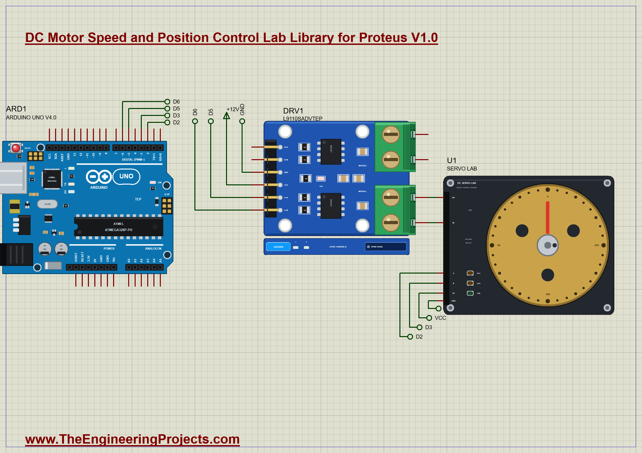
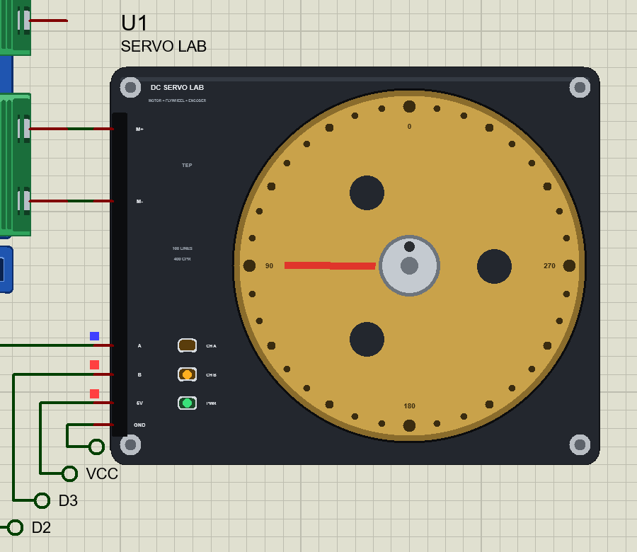
The demo has three parts: our Arduino UNO Library for Proteus V4.0, with its built-in monitor, the same window as our TEP Serial Monitor Advance for Proteus; our L9110S driver; and the servo lab. The UNO drives the L9110S's motor A inputs from D5 and D6, the L9110S runs from 12 V, and its A outputs go straight to the lab's M+ and M-. The encoder's A and B go to D2 and D3, the UNO's two interrupt pins, and the lab's 5V pin goes to the 5 V rail. Open ServoLab-PD-L9110S-ArduinoUnoV4.pdsprj after installing the L9110S library.
The Sketch
The encoder is read in interrupts, on every edge of both channels. The interrupt reads both pins at once and looks up the step in a table of the sixteen possible changes, which counts up, down, or not at all:
void encoder() {                                  // both pins, every edge: x4 decoding
  byte s = (PIND >> 2) & 3;                       // D2 = A (bit 0), D3 = B (bit 1)
  count += QDEC[(ab << 2) | s];
  ab = s;
}
The sketch first runs the bump test: 20 % of the driver's 12 V from 0.2 s, 40 % at 1.2 s, and a stop at 2.4 s. At 3.2 s the PD loop takes over. It runs every 2 ms, takes the speed from the count 10 ms earlier, and switches the motor off within one count of the target, a dead band that stops it hunting about the target against static friction:
    long e = target - c;
    float u = KP * e - (useD ? KD * speed : 0);
    if (labs(e) <= 1) u = 0;                      // within a count of the target: off (static friction would leave it hunting a count or two)
    motor(u);
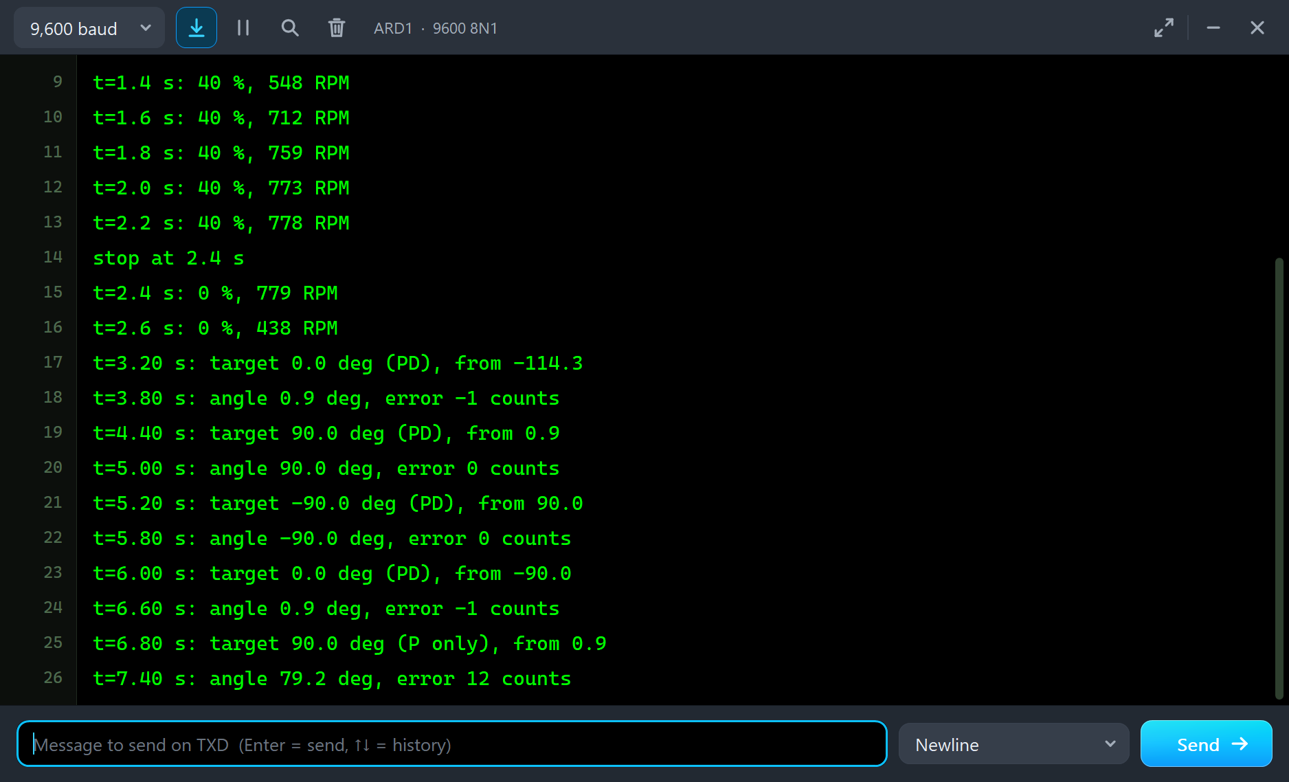
The loop first homes the flywheel to the dial's 0, the nearest whole turn after the bump test's spin, then moves it to +90 degrees at 4.4 s, to -90 at 5.2 s and back to 0 at 6.0 s. At 6.8 s it makes the same move to +90 degrees with the derivative switched off. The gains, 1.13 % of the supply per count and 0.046 % per count per second, are the ones the pop-up suggests from the bump test.
Run the Demo
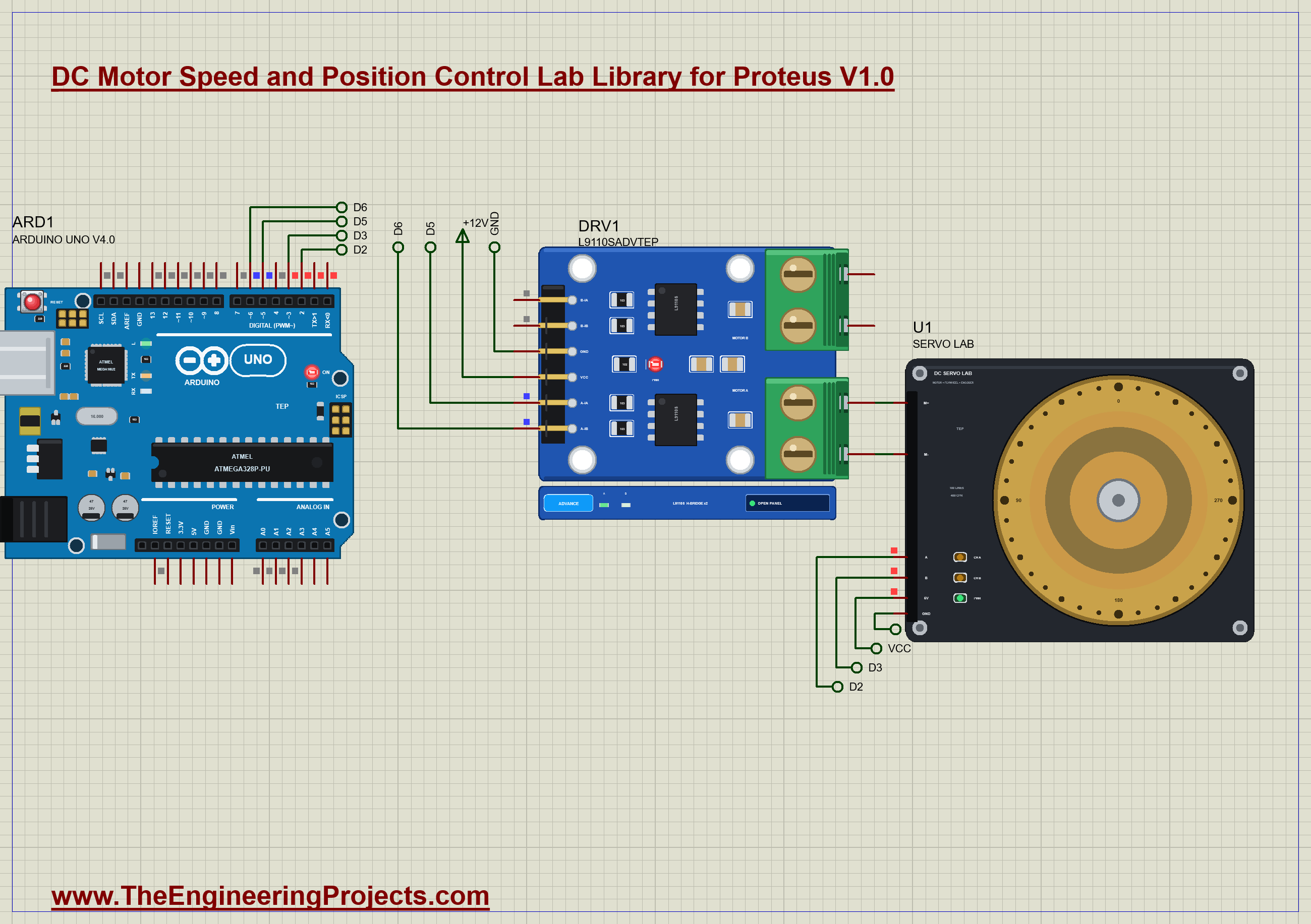
Install the L9110S library, open the project and press Run. The UNO prints its banner, the speed every 0.2 s during the bump test, and a line for every target and every result. The whole demo takes 8.6 simulated seconds, which Proteus ran in under two minutes on our PC. On the sheet the flywheel turns: its holes and index sweep round during the bump test, blurred at speed, the PWR LED is lit, and the CH A and CH B LEDs flicker with the encoder's edges. Click the lab to open its pop-up; everything below is from that one run, the demo exactly as it ships.
The Bump Test
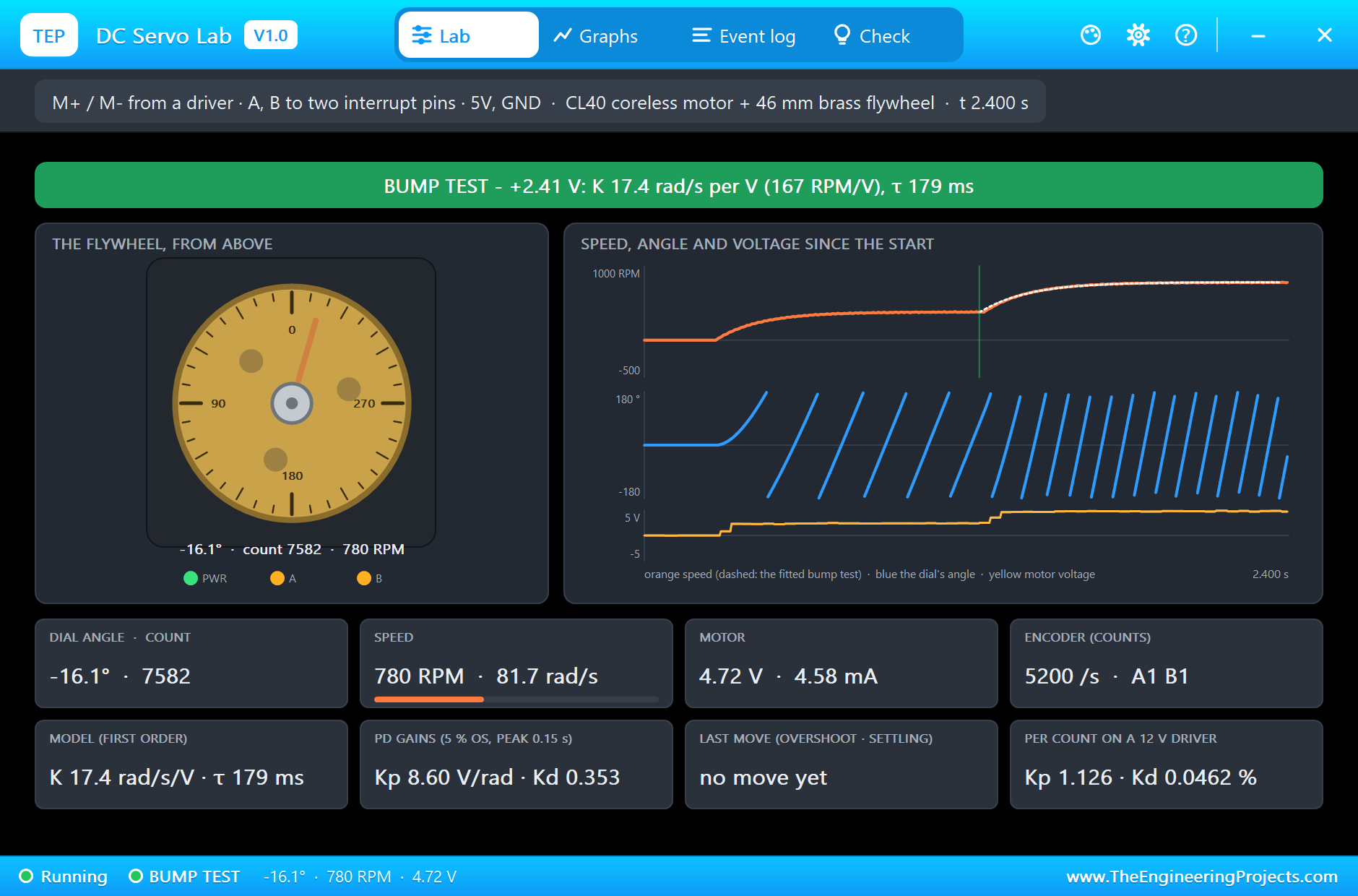
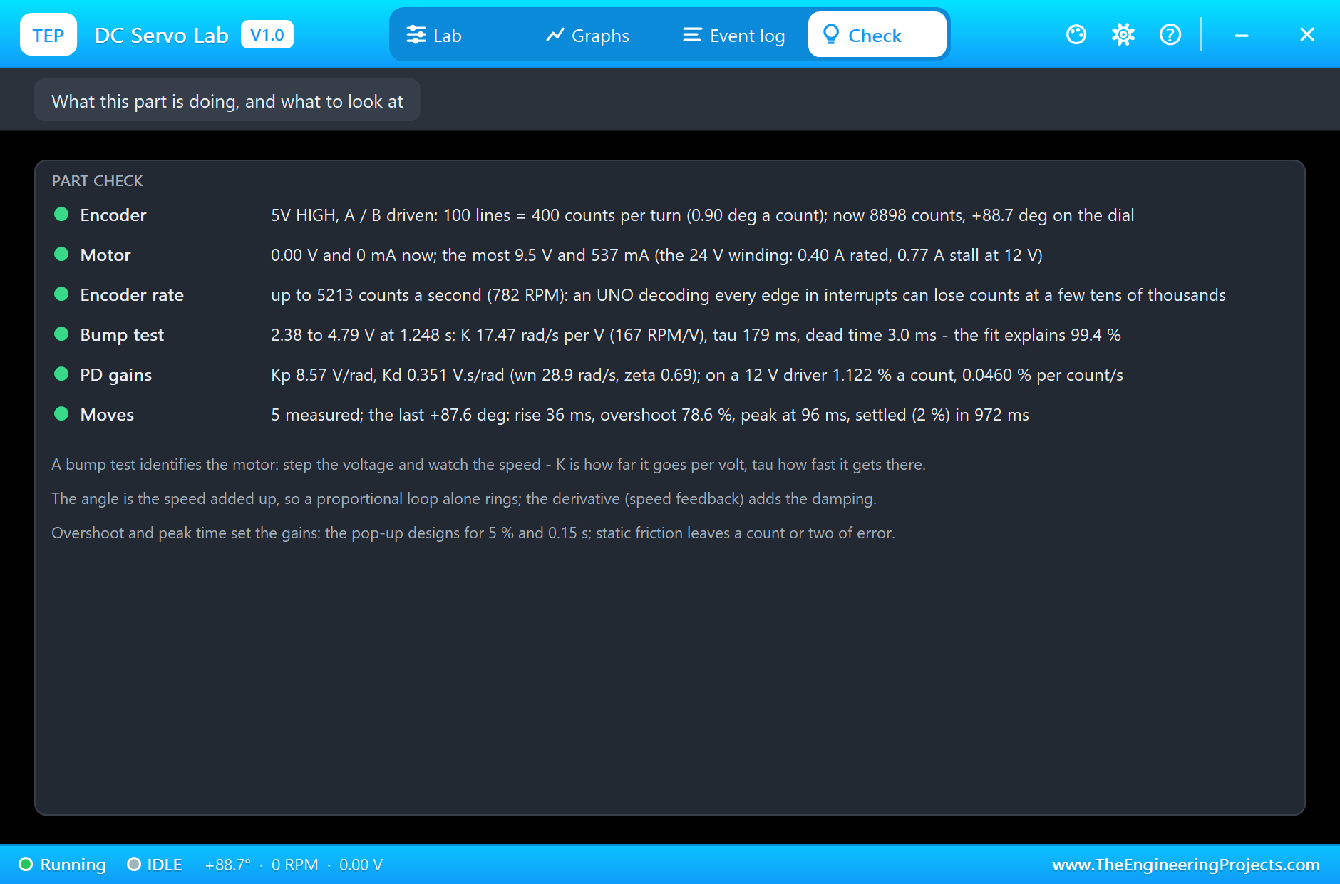
The first step, 0 to 2.31 V from rest, is logged as a bump test too, but the shaft starts against its static friction, and the pop-up's K for it, 16.71 rad/s per volt, is a little low. The second step is the real test: 2.38 to 4.79 V at 1.25 s, from a steady 380 RPM. The speed rises to 548 RPM at 1.4 s, 712 at 1.6 s and 778 at 2.2 s on the UNO's monitor. While it rises the pop-up fits it, and just before the stop its banner reads BUMP TEST - +2.41 V: K 17.4 rad/s per V (167 RPM/V), τ 179 ms, the dashed model lying on the orange speed. The Check page gives the final fit: K 17.47 rad/s per volt, τ 179 ms and a dead time of 3 ms, the fit explaining 99.4 % of the response. K is the motor's own one over 57 mV per rad/s, almost exactly; τ is longer than the motor's 144 ms because the driver's switches add their resistance to the winding's. From the model the pop-up gives Kp 8.57 V/rad and Kd 0.351 V s/rad, which on the 12 V driver are 1.122 % of the supply per count and 0.0460 % per count per second. The sketch's 1.13 and 0.046 come from an earlier run of the same test: the fit moves in its third digit from run to run, and the moves do not notice.
The PD Moves
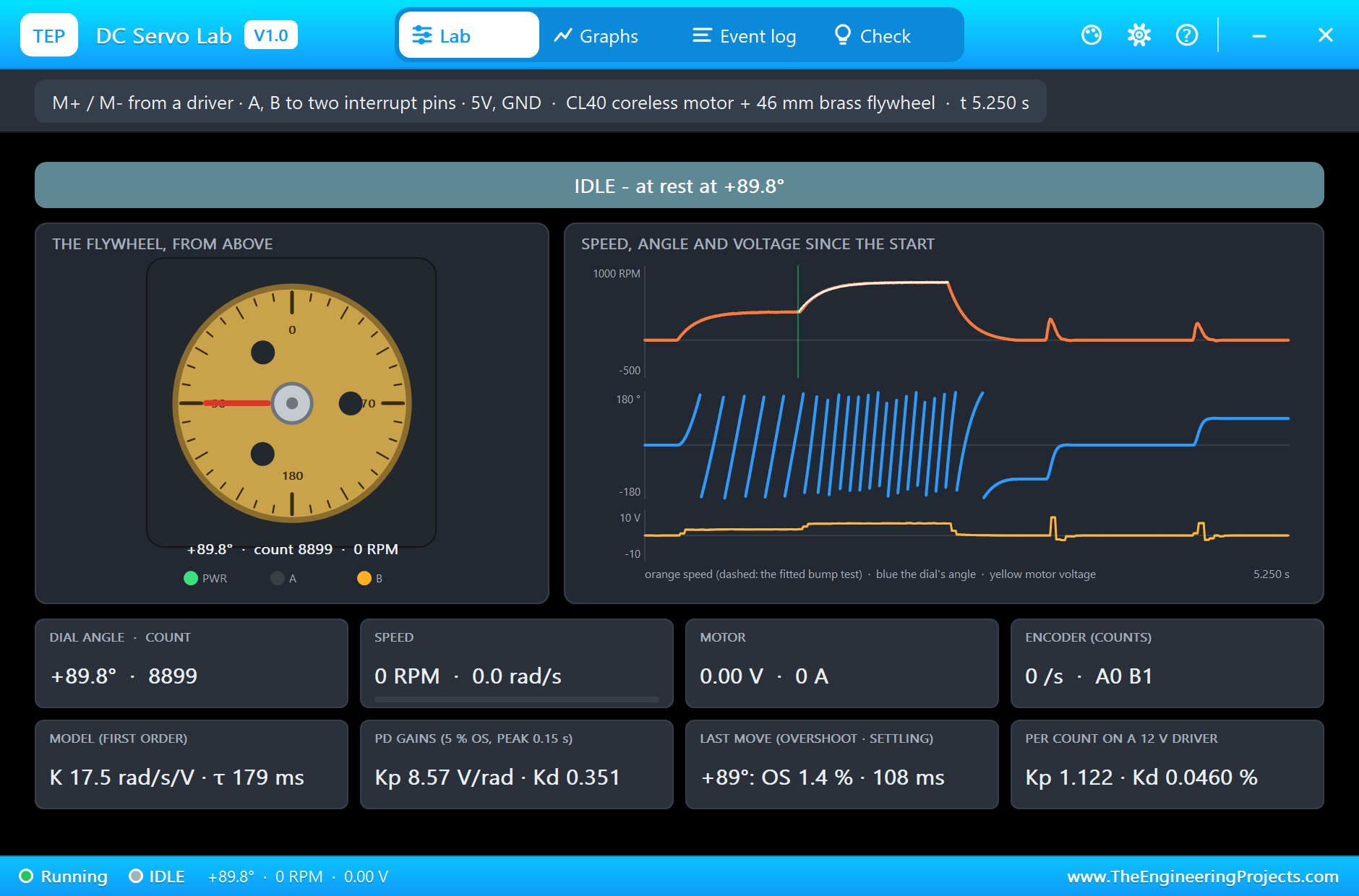
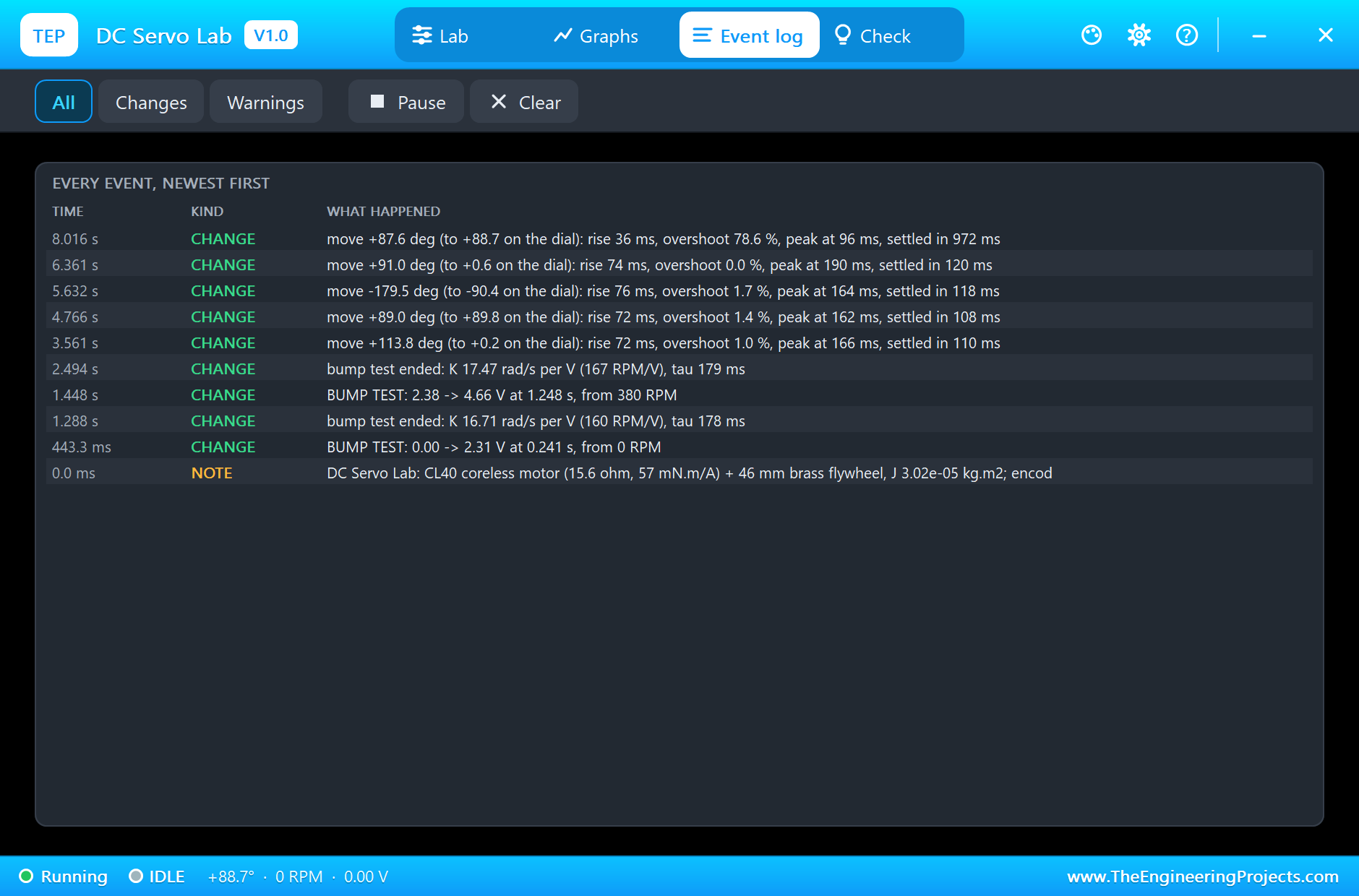
At 3.2 s the flywheel is at -114.3 degrees, where the bump test's stop left it, and the loop homes it to 0. It gets there with 1.0 % overshoot, the peak 166 ms after the step, settled within 2 % in 110 ms, and the UNO reads 0.9 degrees, one count short. Then the move to +90 degrees: 1.4 % overshoot, the peak at 162 ms, settled in 108 ms, and the UNO reads exactly 90.0. The swing from +90 to -90 degrees, twice as far, gives 1.7 % and 118 ms, and the move back to 0 gives no overshoot at all and 120 ms. The design asked for 5 % overshoot and the peak at 0.15 s: the moves come out a little better damped, because the motor's friction and the driver's resistance add damping the first-order model does not include, and the peaks arrive between 0.16 and 0.19 s. Each move's rise time, from 10 % to 90 % of the way, is 72 to 76 ms.
The P-Only Move
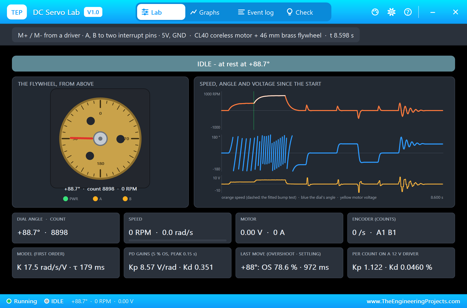
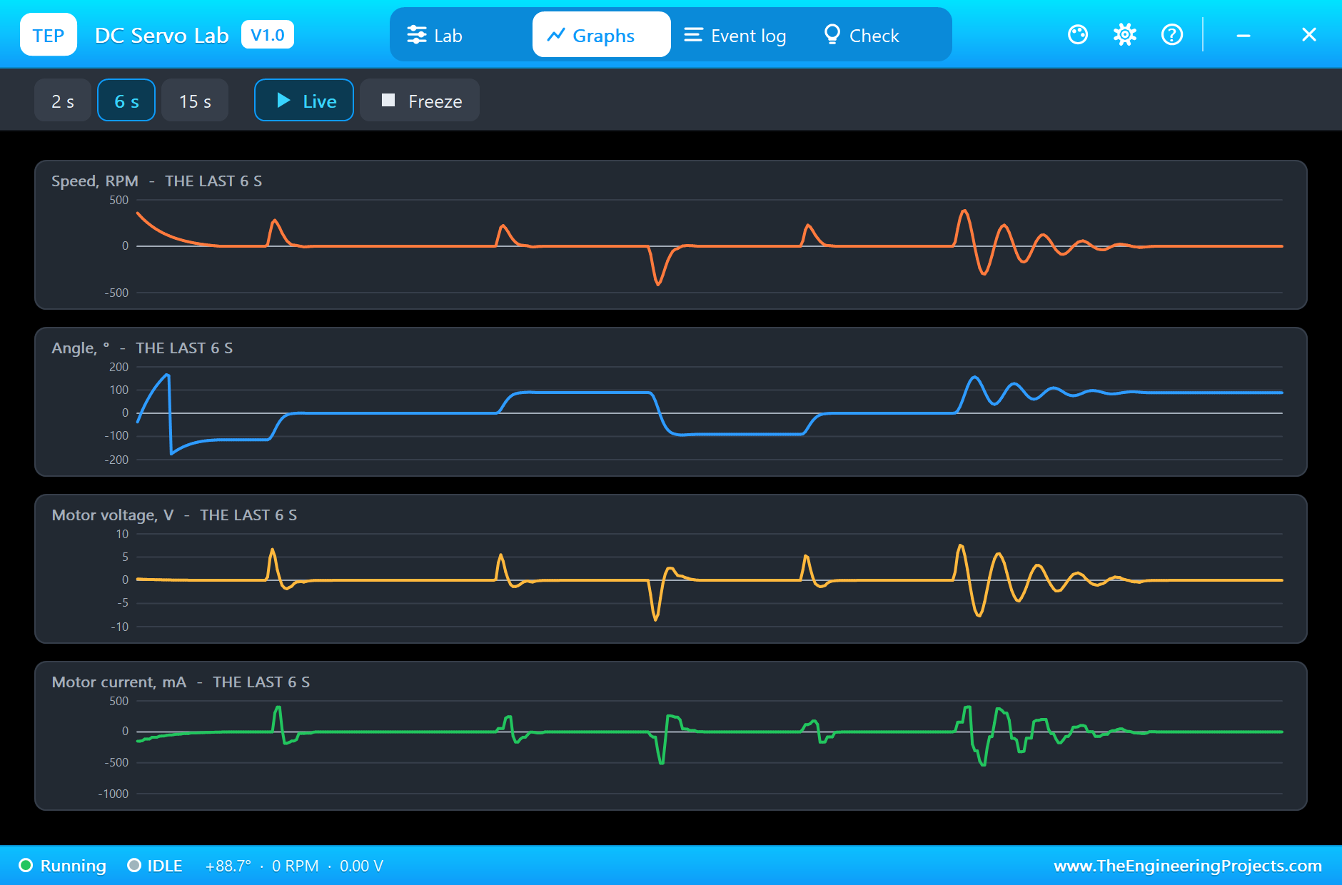
At 6.8 s the sketch makes the same move to +90 degrees with the derivative off. The flywheel rises much faster, 36 ms from 10 % to 90 %, but it shoots to 78.6 % past the target 96 ms after the step, swings back past it, and rings for almost a second; the pop-up measures 972 ms to settle within 2 %. At 7.4 s, 0.6 s after the step, the UNO still reads 79.2 degrees, 12 counts short, on one of the swings. The trend on the main page shows the difference at a glance: four clean steps of the blue angle, then a decaying oscillation.
The Monitor
The UNO's monitor shows the sketch's side of the same run. During the bump test it prints the speed every 0.2 s from its own count; then, for every move, the target and where it started, and 0.6 s later the angle and the error in counts: 0.9 degrees and -1 count after homing, 90.0 and -90.0 degrees with no error, 0.9 degrees and -1 count back at 0, and 79.2 degrees with 12 counts to go on the P-only move. The UNO's count and the lab's agree within a count all the way.
The Graphs, the Log and the Check Page
The Graphs page plots the speed, the dial's angle, the motor voltage and the motor current over the last 2, 6 or 15 simulated seconds; the 6-second window holds every move of the demo. Each PD move is one hump of speed and one short burst of voltage; the P-only move is a train of them. The current peaks at 537 mA, below the motor's 0.77 A stall current at 12 V. The Event log lists both bump tests with their fits, and each move with its size, the dial angle it ended on, its rise time, overshoot, peak time and settling time.
The Check page sums up the part. The encoder is green: 5V is high, 400 counts per turn, 0.9 degrees a count, and the count and the dial angle now. The motor row gives the voltage and current now and the most of the run, 9.5 V and 537 mA. The encoder rate peaked at 5,213 counts a second at 782 RPM, comfortable for an UNO. The bump test, the PD gains and the moves repeat the numbers above.
The Driver's View
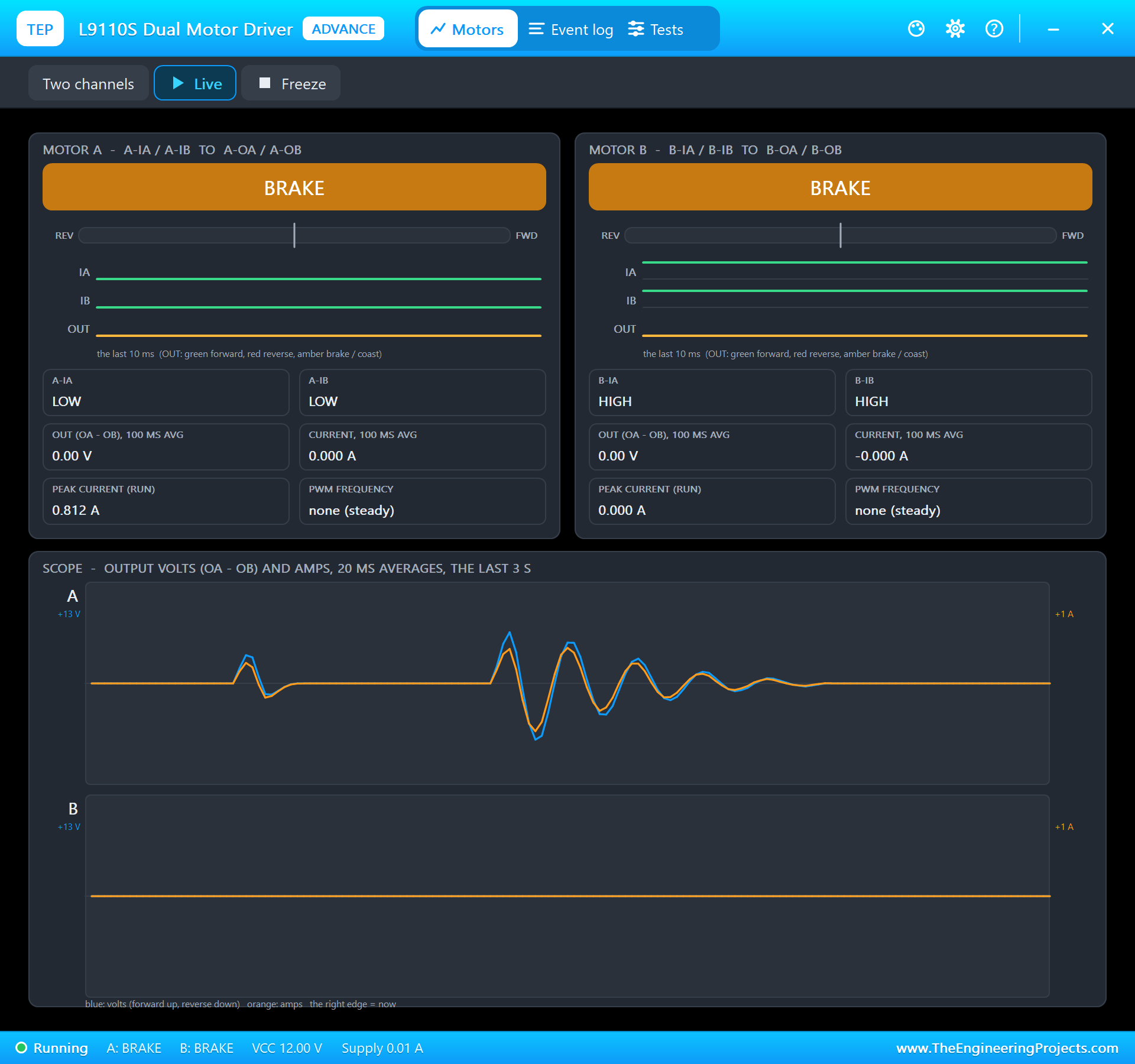
The L9110S has its own pop-up. Its scope shows the voltage and current on motor A over the last 3 seconds: the short bursts of the PD moves and the long ring of the P-only move. Its peak current for the run, 0.812 A, is an instant at the start of a move, when the motor is still and only the winding's resistance limits the current.
Try It Yourself
- Double KD and watch the moves get sluggish; halve it and watch the overshoot grow towards the P-only move.
- Set LOAD to 2 mN m: K stays, but the flywheel stops further from the target, the friction a P term has to beat.
- Change LINES to 500: 2,000 counts per turn, a finer angle, and four times the interrupts at the same speed.
- Run a speed loop instead: a PI controller that holds 600 RPM, with the gains from the same K and τ.
- Remove the dead band and watch the loop hunt a count or two about the target.
Ideas to Extend the Demo
- Add an integral term and a load, and see the steady error vanish.
- Send the count to a PC over serial and fit the model yourself in Python or MATLAB.
- Make the target follow a potentiometer, or a sine wave, and measure the tracking error.
- Try a different overshoot and peak time and compare the measured moves with the design.
Your Own Sketches
The demo sketch is in the zip file, and you can change it in the Arduino IDE. New to Arduino? Start with our Arduino Tutorial for Beginners. Export the compiled binary, and set the UNO's PROGRAM property to the new file. Our guide on How to get the HEX file from Arduino shows you where the file ends up.
Things to Know Before Using a Real Lab
- Keep clear of the flywheel: at 2,000 RPM a 99 g disc carries real energy; keep fingers and cables away.
- Decode both edges of both channels: that is 400 counts per turn; above a few tens of thousands a second an UNO falls behind.
- Identify first, then tune: a bump test gives K and τ; the gains follow from the overshoot and the peak time you want.
- Mind the friction: it leaves a count or two of error, and a one-count dead band stops the hunting.
- Watch the current: a step from rest draws the stall current for an instant; size the driver for it.
Troubleshooting
- NO ENCODER SUPPLY: the shaft turns but the 5V pin is LOW, so A and B float; connect 5V.
- The count drifts from the dial: the sketch must decode both edges of A and B, with two CHANGE interrupts.
- The bump test is not fitted: hold a voltage for 0.15 s, then step it by 1 V or more, not to 0 V, and hold it until the speed settles.
- STALLED: volts on the motor and the shaft does not turn; check LOAD and the driver's wiring.
- The part is not simulated:
TEPSERVOLAB.DLLis missing from MODELS and from the project folder.
Limitations of the Simulation
- The winding's inductance is left out; at 0.14 ms it is far faster than the mechanics.
- The encoder is perfect: no jitter, no missing slots; the brushes make no noise.
- The friction values are our own choice, set to match the motor's 16 mA no-load current.
- Arduino is a name of Arduino, and the CL40 is a motor of Allied Motion; this library is not made or endorsed by Arduino, Allied Motion or Labcenter.
- Tested in Proteus 8.5 in November 2026 (the demo as shipped). Proteus 7 is not supported.
So, that was all about the DC Motor Speed and Position Control Lab Library for Proteus. I hope it helps you run a real servo lab on your own PC: a bump test, a model, a designed PD loop and the flywheel snapping to its angle, the way the course does it. If you have any questions, ask in the comments and I will help you out. Till the next tutorial, take care and have fun!