Hello friends, I hope you all are doing great. Today, I am going to share the new DRV8833 Motor Driver Library for Proteus Simulation, the 47th library of our motor series. If you have searched for a Proteus simulation of the DRV8833, the small dual H-bridge that runs the two wheels of so many robot cars, this library brings the module into Proteus with both of its bridges, its input table, the slow and fast decay of its PWM, the sleep pin and the fault pin.
DRV8833 Motor Driver Library for Proteus Simulation
Latest version: V1.0 (November 2026, this tutorial)
Other motor drivers: L298 · L9110S · TB6612FNG · BTS7960 · A4988 / DRV8825 · 28BYJ-48 + ULN2003 · PCA9685 Servo · Relay Module · 30A Brushless ESC · TB6600 Stepper Driver · 60A Brushed ESC · DRV2605L Haptic Driver · ZS-X11H BLDC Driver · SimpleFOC Mini Driver · AC Dimmer Module · TMC2209 Stepper Driver · L293D Motor Shield
Motors: SG90 Servo · TT Gear Motor · 28BYJ-48 Stepper · NEMA 17 Stepper · MG996R Servo · N20 Encoder Motor · JGA25-370 Encoder Motor · FS90R 360 Servo · 130 DC Motor · A2212 Brushless · X27.168 Gauge · Analog Panel Meter · DC Tachogenerator · LM393 Speed Sensor · MG90S Servo · DS3218 Servo · L12 Linear Servo · JGB37-520 Motor · RS-775 Motor · JGY-370 Worm Motor · 12V Linear Actuator · Coin Vibration Motor · Mini Submersible Water Pump · 12V Peristaltic Pump · 4-Pin PC Fan · 12V Push-Pull Solenoid · NEMA 23 Stepper Motor · Micro Linear Stepper · TYJ50 Synchronous Motor · Quartz Clock Movement · Air-Core Gauge · Electromechanical Counter · Split-Flap Display · Electric Bell · Wind Turbine · 8520 Coreless Motor · Car Wiper Motor · Car Door Lock Actuator · 12V Solenoid Water Valve · 12V Holding Electromagnet · Mini Air Pump · Planetary Gear Motor · 540 RC Motor · LRA Vibration Motor · 42BLF Hall BLDC Motor · 2204 Gimbal Motor · 120mm 230V AC Fan · NEMA 17 Closed-Loop Stepper · NEMA 17 Linear Stage · Pan-Tilt Bracket · 4-DOF Robot Arm
Helping Tools
- Serial Monitor Advance: a serial terminal window for the UART of your board
- Serial Monitor Expert: the serial monitor with extra debugging tools
- LCD Library for Proteus V3.0: 16x2, 20x4 and I2C LCDs to show your readings
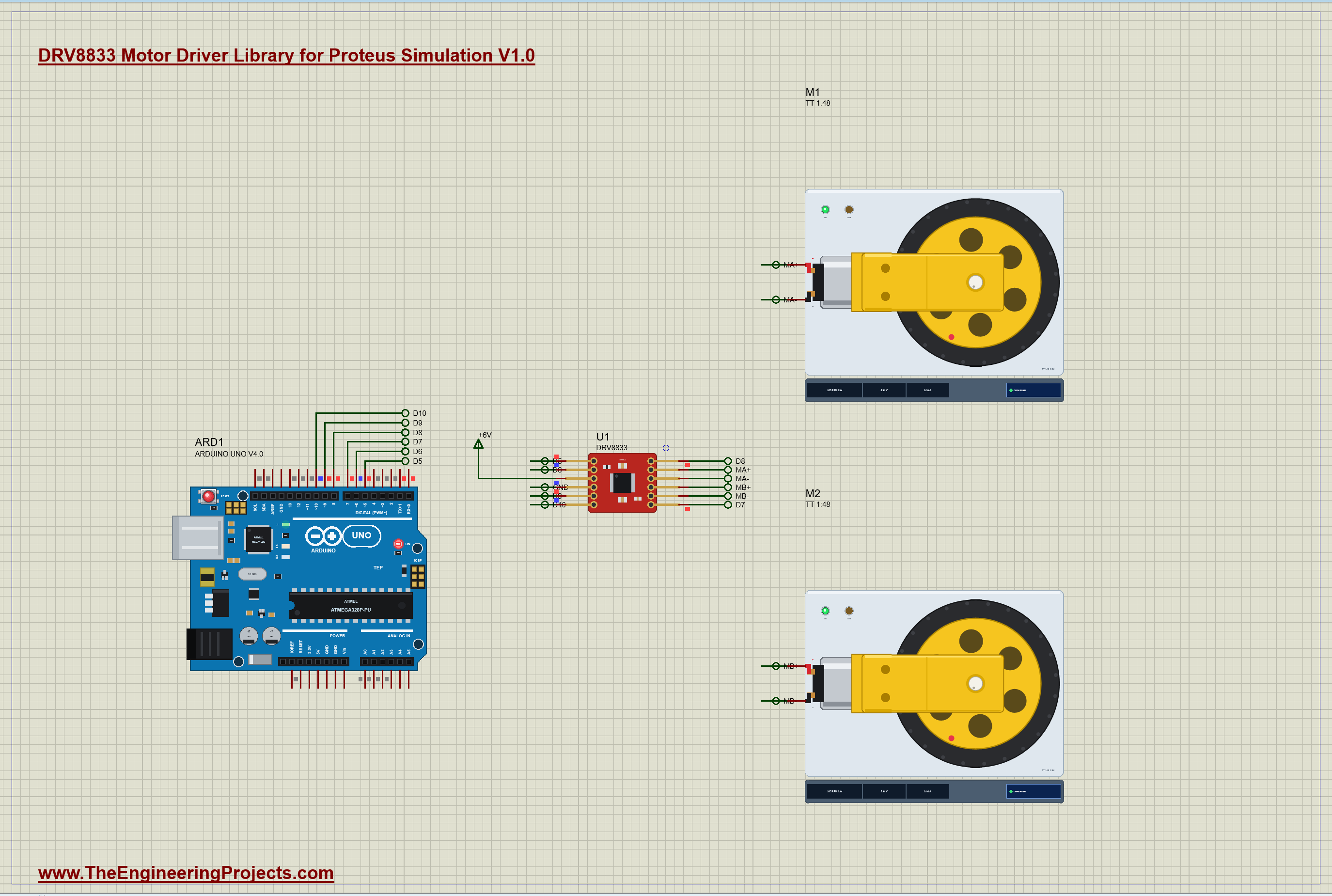
The module is drawn at its true size, the little 18.5 x 16 mm red board with the DRV8833 chip in the middle and its two rows of six pins. The simulation model drives each motor through an H-bridge of four switches, solved together with the motor, so you can see what the input table really does to a motor: forward, reverse, brake and coast, and the two different ways the same PWM can slow a motor down. In the demo an Arduino drives two of our TT gear motors and puts the two bridges side by side, so every difference shows on the wheels.
NOTICE: Our team has put a lot of effort into these small parts: the bodies, the animation and the pop-ups are all our own design, and you get them free. Your feedback is the fuel that keeps us going, so please tell us what you think in the comments below or in the Motor Driver board of our forum. And if our free libraries help you, you can buy us a coffee. So, let's get started with the DRV8833 Motor Driver Library for Proteus Simulation:
What is the DRV8833 Motor Driver?
A microcontroller pin can give a few milliamperes; a small DC motor needs a few hundred, and it needs them in both directions. An H-bridge solves both problems: four switches around the motor, two on each side, so that either end of the motor can be connected to the supply or to ground. The DRV8833 from Texas Instruments has two complete H-bridges in one small chip, so one module drives two DC motors, the left and right wheels of a robot, or the two coils of one small stepper motor.
It is popular for battery robots because it works from a very low voltage, 2.7 V, which suits two AA cells, a single Li-ion cell or a 6 V pack, and because its switches are MOSFETs with a low resistance, so it wastes far less of the battery than the old L298N with its bipolar transistors. The module needs no logic supply of its own; the chip makes its own from the motor supply, and its inputs accept 3.3 V or 5 V logic.
| The DRV8833 module (the common 12-pin board) | |
|---|---|
| Motor supply (VCC) | 2.7 to 10.8 V (11.8 V absolute maximum) |
| Current | 1.5 A RMS, 2 A peak a bridge; 3 A RMS with the two bridges in parallel |
| Switches | 0.36 ohm a bridge, high side plus low side (0.20 + 0.16 ohm at 5 V) |
| Inputs | IN1 IN2 for OUT1 OUT2 (bridge A), IN3 IN4 for OUT3 OUT4 (bridge B), with pull-downs |
| EEP | the chip's nSLEEP: high = on, low = sleep (1.6 uA), 1 ms to wake |
| ULT | the chip's nFAULT: open drain, low on over-current, over-temperature or under-voltage |
| Board | about 18.5 x 16 mm, two rows of six pins on a 0.1 inch pitch |
The Input Table: Forward, Reverse, Brake and Coast
Each bridge has two inputs, and the four combinations of their levels are the whole interface. With xIN1 high and xIN2 low, xOUT1 is driven high and xOUT2 low: the motor turns forward. The other way round it turns in reverse. With both inputs high, both outputs are driven low: the motor's two wires are shorted together through the low-side switches, and its own back-EMF drives a current that brakes it hard. With both inputs low, all four switches open: the motor is disconnected and coasts to a stop on its own friction.
| xIN1 | xIN2 | xOUT1 xOUT2 | The motor |
|---|---|---|---|
| 1 | 0 | H L | forward |
| 0 | 1 | L H | reverse |
| 1 | 1 | L L | brake (slow decay) |
| 0 | 0 | open | coast (fast decay) |
The difference between brake and coast matters more than it looks. A braked motor stops in a fraction of the time, which a robot needs to stop where it should. A coasting motor rolls on, which saves energy and is gentler on a gearbox. The demo stops one wheel each way at the same moment, so you can see both.
Slow Decay and Fast Decay PWM
For the speed, the Arduino puts a PWM signal on one input. The other input decides what happens in the off part of every PWM period, and that is the meaning of the two names in the datasheet. With the other input LOW, the off time is coast: all four switches open and the motor's current dies away through the switches' body diodes, quickly, which is why it is called fast decay. With the other input HIGH, the off time is brake: both low sides on, the motor shorted, and its current decays slowly, which is slow decay.
Slow decay gives the better speed control. In every off time the motor is braked, so if it runs faster than the duty asks for, it is pulled back at once, and its speed follows the duty closely in both directions. In fast decay the motor cannot be braked down: it can only be pushed, so when the duty drops it coasts down to the new speed on its own friction. There is one trap: in slow decay with xIN1 high, the PWM goes on xIN2, so a larger duty on xIN2 means more braking time and a SLOWER motor; the sketch has to invert the value.
Features of the DRV8833 Motor Driver Library for Proteus Simulation
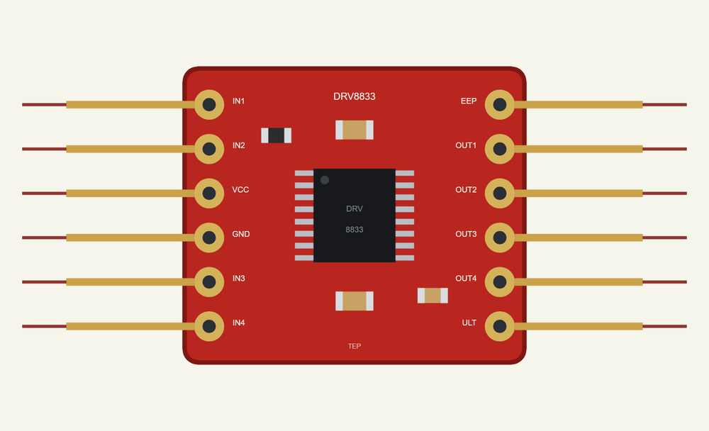
- The module at true scale: the 18.5 x 16 mm red board with the DRV8833 and its two rows of six pins, IN1 IN2 VCC GND IN3 IN4 and EEP OUT1 OUT2 OUT3 OUT4 ULT.
- Two H-bridges: 0.36 ohm each, averaged and solved with the motors; every output has its two body diodes.
- The input table: forward, reverse, brake and coast, and a PWM on either input with slow or fast decay, each input's PWM measured period by period.
- EEP and ULT: sleep with its 1 ms wake-up; ULT low on an over-current (2.6 A in the model, 2 to 3.3 A in the datasheet, the bridge retried every 1.35 ms), over-temperature or under-voltage.
- A pop-up: the two bridges with their switches lit by their share of the time, each motor's voltage and current, the input table with each bridge's row lit, the sleep and fault flags, eight live values, graphs, an event log and a check page.
- A complete package: about 1.2 MB with the library, our Arduino UNO V4.0 and the demo, without the source code of the model.
The DRV8833 in Proteus
The device is DRV8833TEP in TEPDRV8833.LIB, under Electromechanical > Motor Drivers, with the prefix U and the mixed model TEPDRV8833.DLL. Search DRV8833 in Pick Devices. The pins follow the module: IN1, IN2, VCC, GND, IN3 and IN4 on the left; EEP, OUT1, OUT2, OUT3, OUT4 and ULT on the right. It has no properties: like the real module, the inputs set everything.
Download DRV8833 Motor Driver Library for Proteus Simulation
Click the button below to download DRV8833-Motor-Driver-Library-for-Proteus-v1.0.zip (about 1.2 MB, without the source code of the models):
DRV8833 Motor Driver Library for Proteus V1.0- README.txt: installation, the demo, the wiring, troubleshooting and the limits of the simulation.
- Proteus Library Files:
TEPDRV8833.LIBandArduinoV4TEP.LIB. - Proteus Model Files:
TEPDRV8833.DLLandTEPARDUINO.DLL. - Arduino Code: the demo sketch.
- Proteus Simulation: the demo project, its HEX file and copies of the DLLs.
No Proteus yet? Read How to Download and Install Proteus 7 and 8. New to libraries? Follow How to Install a New Library in Proteus.
How to Install DRV8833 Motor Driver Library for Proteus Simulation
- Close Proteus and extract the whole zip file, for example to your Desktop.
- Copy the files from Proteus Library Files into the LIBRARY folder of Proteus.
- Copy the files from Proteus Model Files into the MODELS folder.
- Delete
TEPDRV8833.IDXfrom the LIBRARY folder if it is there. - The demo's motors are our separate TT Gear Motor Library for Proteus: install its LIB and DLL too.
- Start Proteus, press P and search for DRV8833.
Proteus Simulation of the DRV8833 with Arduino
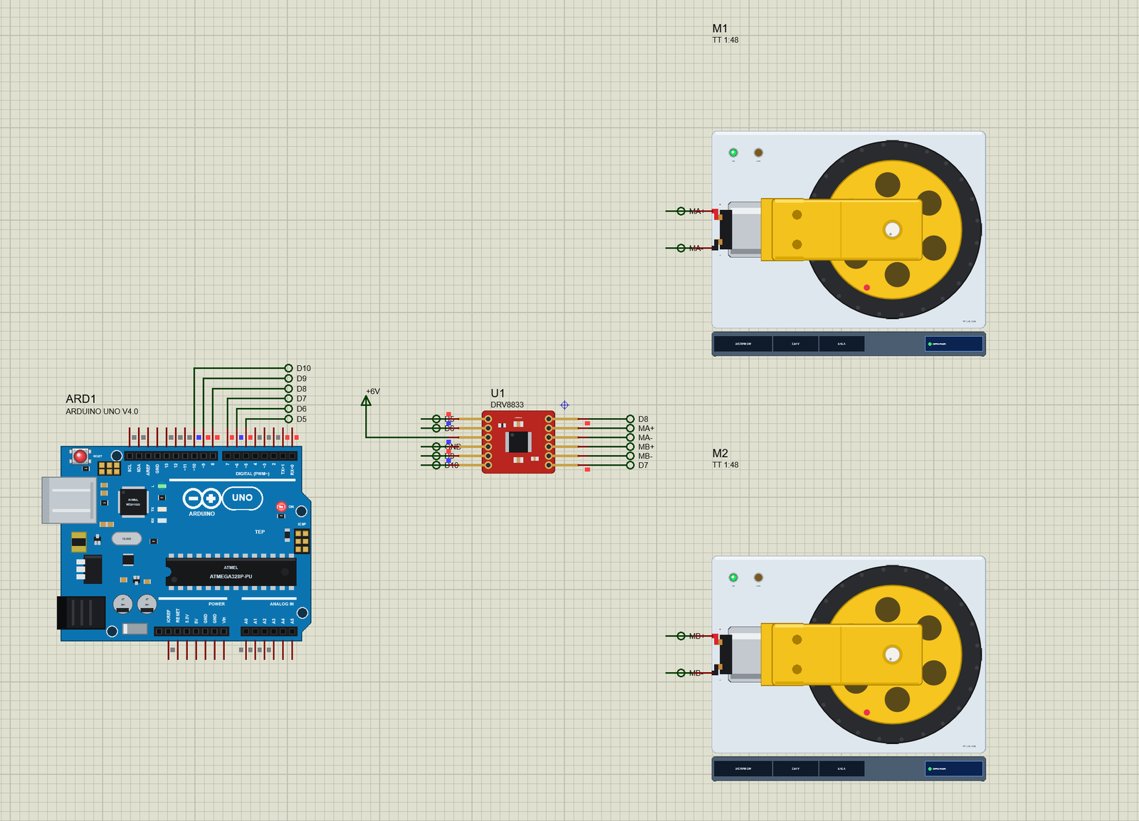
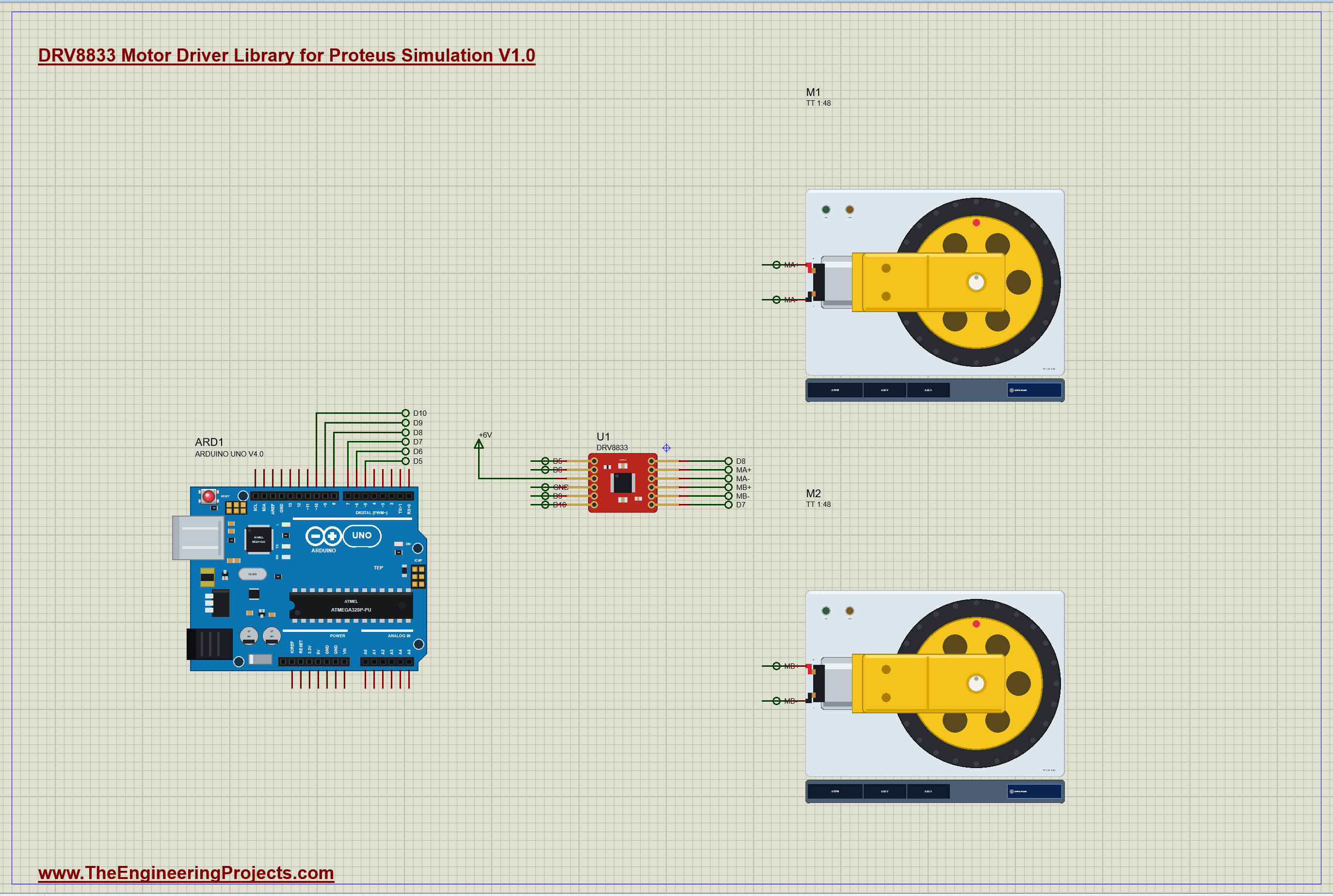
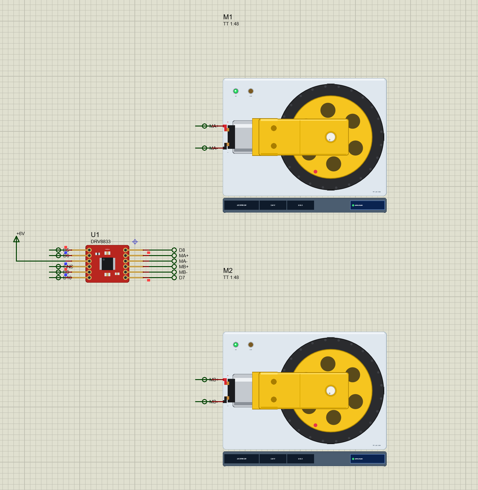
The demo has our Arduino UNO Library for Proteus V4.0 with its built-in monitor, the same window as our TEP Serial Monitor Advance for Proteus. U1 is the DRV8833 with VCC on a 6 V terminal. The UNO drives IN1 from D5, IN2 from D6, IN3 from D9 and IN4 from D10, all four PWM pins, EEP from D8, and reads ULT on D7 with its internal pull-up. The motors are two of our TT gear motors from our separate TT Gear Motor library (TEPTTGEAR.LIB and TEPTTGEAR.DLL), so install it first: M1 on OUT1 and OUT2 is motor A, M2 on OUT3 and OUT4 is motor B. Open DRV8833-TTGEAR-ArduinoUnoV4.pdsprj.
The Sketch
One small function turns a speed from -255 to 255 into the two input values of a bridge, with slow or fast decay. Note the inverted value in slow decay:
void drive(uint8_t p1, uint8_t p2, int speed, bool slow) {
  speed = constrain(speed, -255, 255);
  if (speed >= 0) { if (slow) bridge(p1, p2, 255, 255 - speed); else bridge(p1, p2, speed, 0); }
  else { if (slow) bridge(p1, p2, 255 + speed, 255); else bridge(p1, p2, 0, -speed); }
}
Brake and coast are just the two inputs both high or both low:
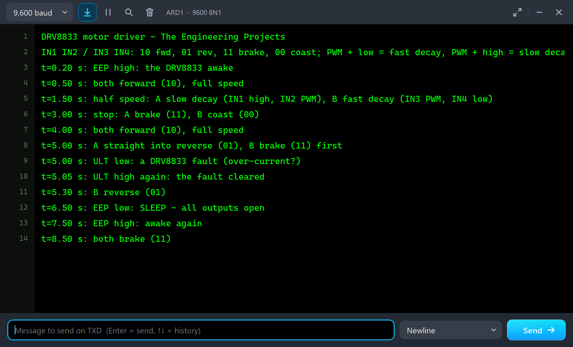
case 3: bridge(IN1, IN2, 255, 255); bridge(IN3, IN4, 0, 0); say(F("stop: A brake (11), B coast (00)")); break;ULT blinks during an over-current, because the DRV8833 retries every 1.35 ms, so the sketch reports it once and waits until it has stayed high for 50 ms:
if (low) { if (!ultLow) { ultLow = true; say(F("ULT low: a DRV8833 fault (over-current?)")); } ultSince = ms; }The program sets EEP high at 0.2 s, runs both motors forward at 0.5 s, halves the speed at 1.5 s with A in slow decay and B in fast decay, stops at 3 s with A braked and B coasting, runs both forward again at 4 s, sends A straight into reverse at 5 s while B is braked first and reversed at 5.3 s, sets EEP low at 6.5 s and high at 7.5 s, and brakes both at 8.5 s. Afterwards you can type a 150, b -200, x, c or e 0 in the monitor.
DRV8833 Simulation Results
Open the project and press Run. The program runs about 9 simulated seconds; with the three pop-ups open and the pictures being taken it took about three minutes on our PC. Click the DRV8833 for its pop-up and each motor for its own. Every number below comes from one simulation run, the demo exactly as it ships. One detail to know when you compare the times: the UNO's program starts about 66 ms after the simulation, so the monitor's times read a little earlier than the pop-ups'.
Both Motors Forward
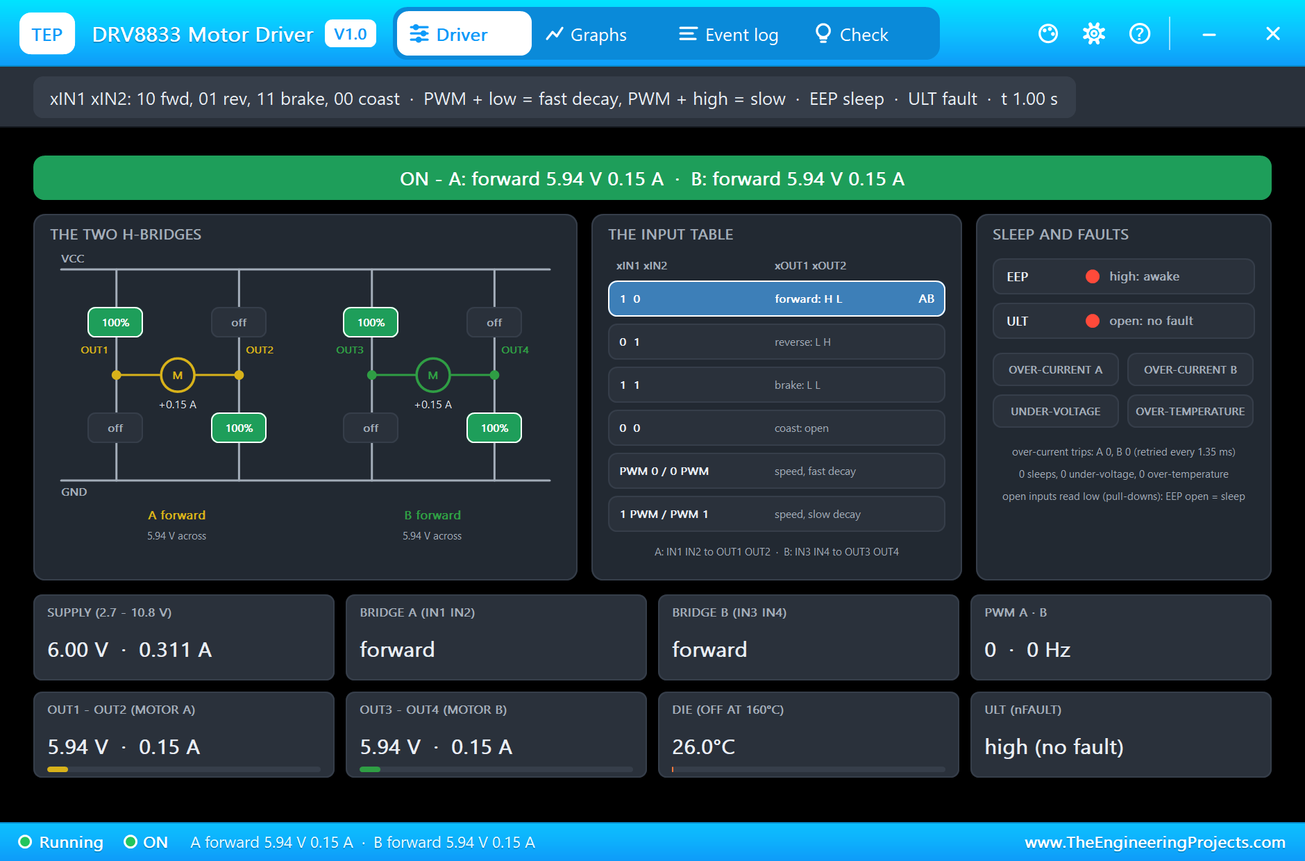
At 1 s both bridges are in the forward row of the table, lit for A and B. Each H-bridge has its upper left and lower right switch on, and each motor gets 5.94 V at 0.15 A: the 6 V supply less the drop across the 0.36 ohm bridge. In the simulation the module draws 0.311 A in all.
Half Speed: Slow Decay against Fast Decay
At 1.5 s the UNO asks both motors for half speed, 50 %: bridge A with IN1 high and a PWM on IN2 (slow decay, 977 Hz on D6), bridge B with a PWM on IN3 and IN4 low (fast decay, 490 Hz on D9). Look 0.1 s later. Bridge A is in its slow-decay row with 2.98 V across its motor: in every off time its motor is shorted, so it is braked down, and its pop-up already shows 128 RPM. Bridge B shows "open: coasting": its motor's back-EMF, 4.18 V, is above what half the duty can give, the bridge cannot push it down, and the motor still runs at 190 RPM on its own momentum.
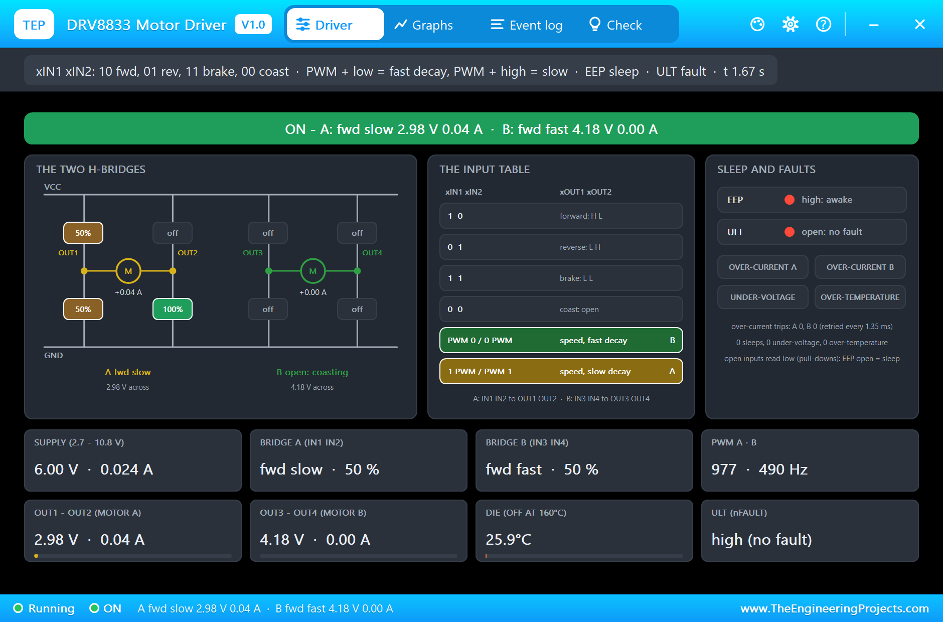
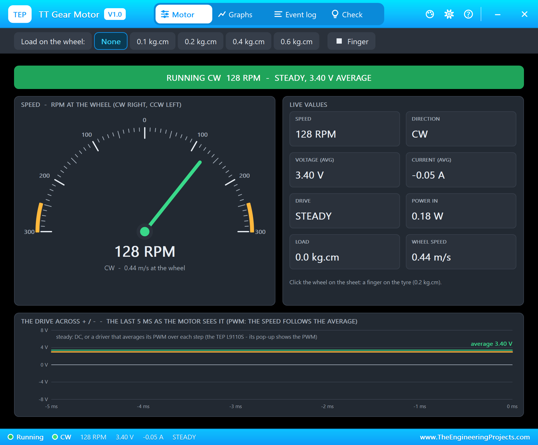
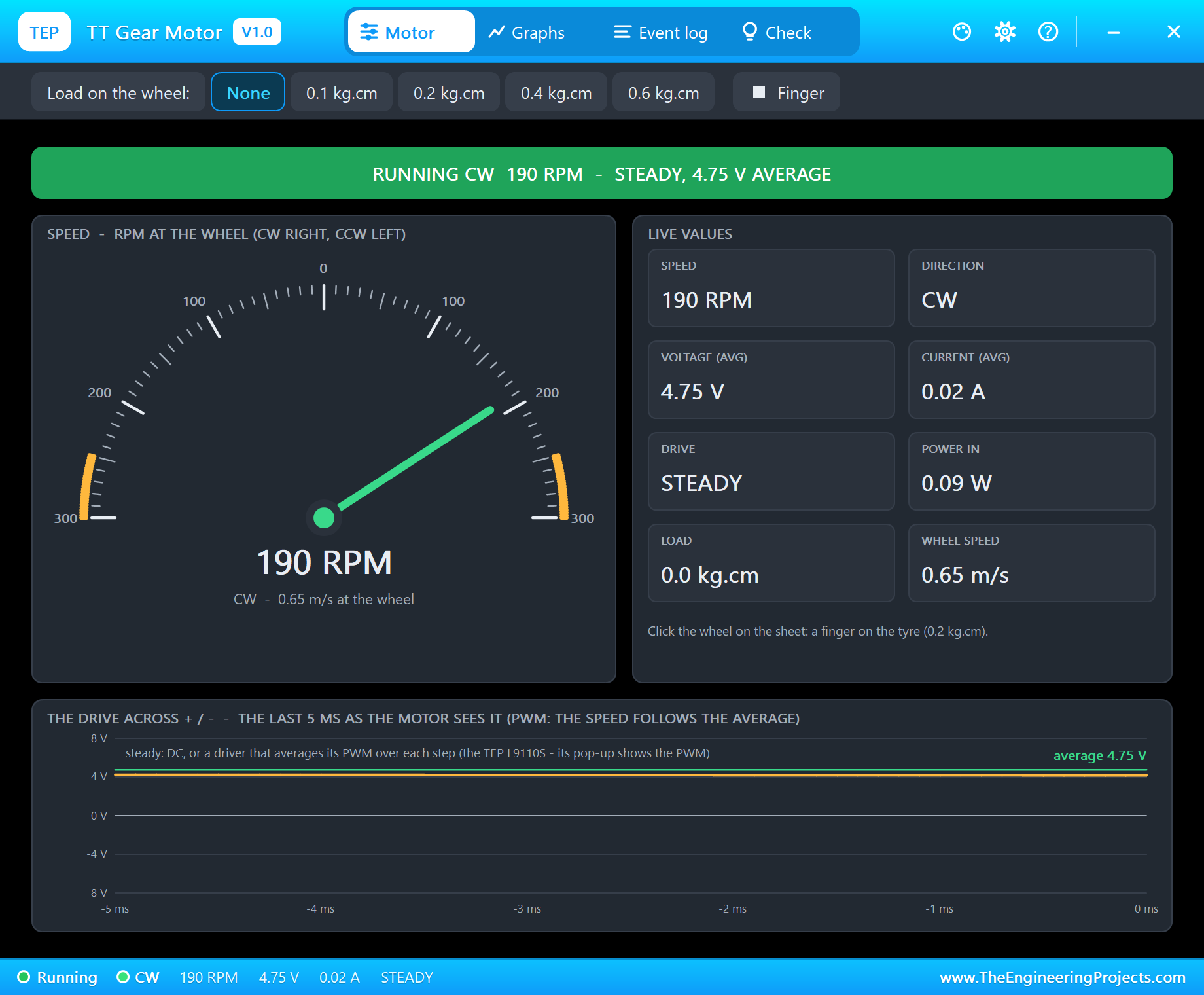
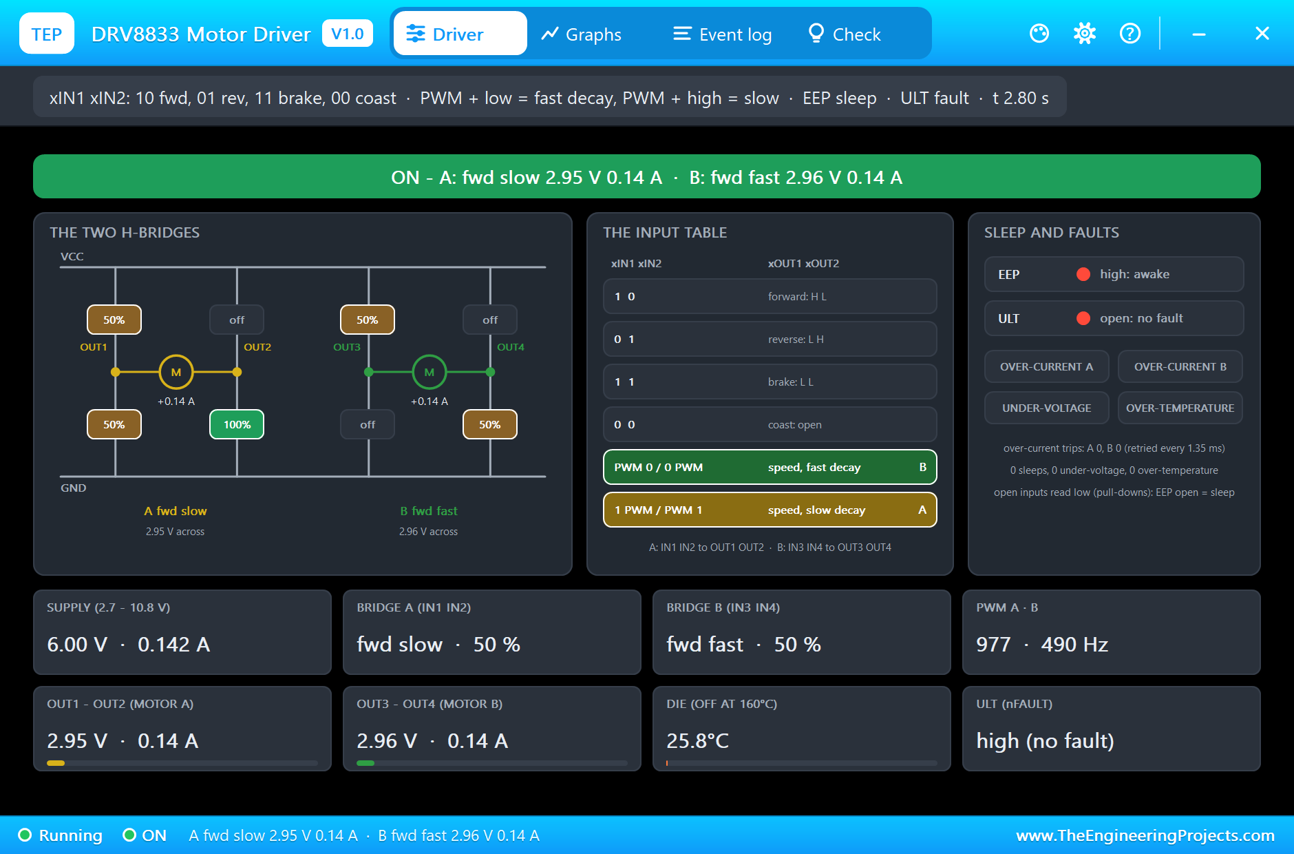
Once motor B has slowed to the speed its duty can hold, both bridges drive again, and at 2.8 s the two motors run the same: 2.95 V and 0.14 A each. In this simulation, as on the bench, the difference between the two decay modes shows when the speed has to come DOWN.
Brake against Coast
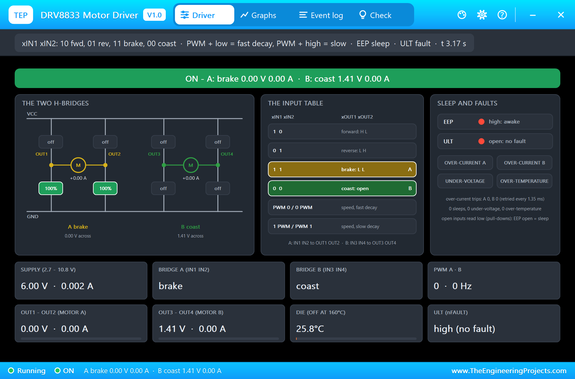
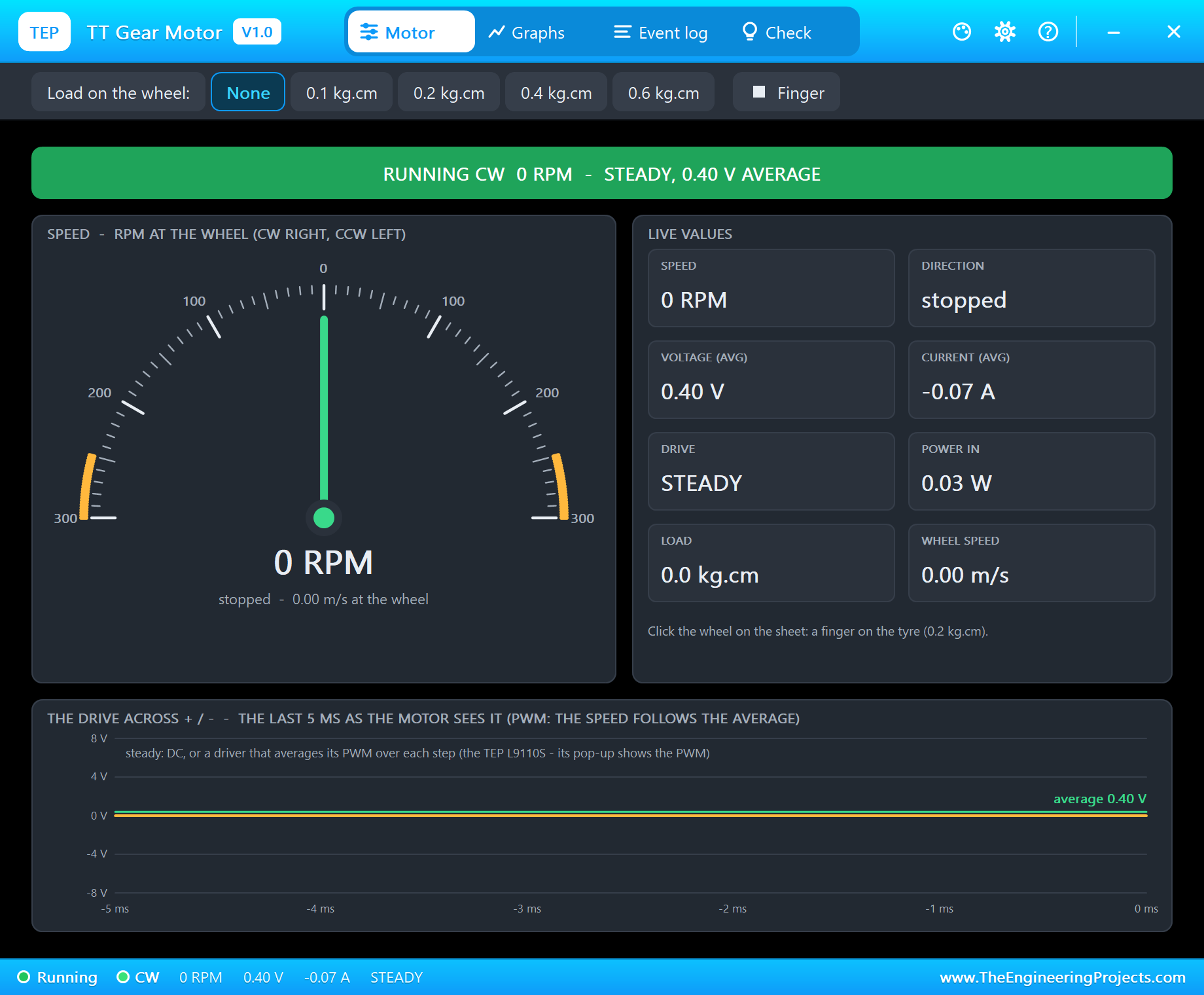
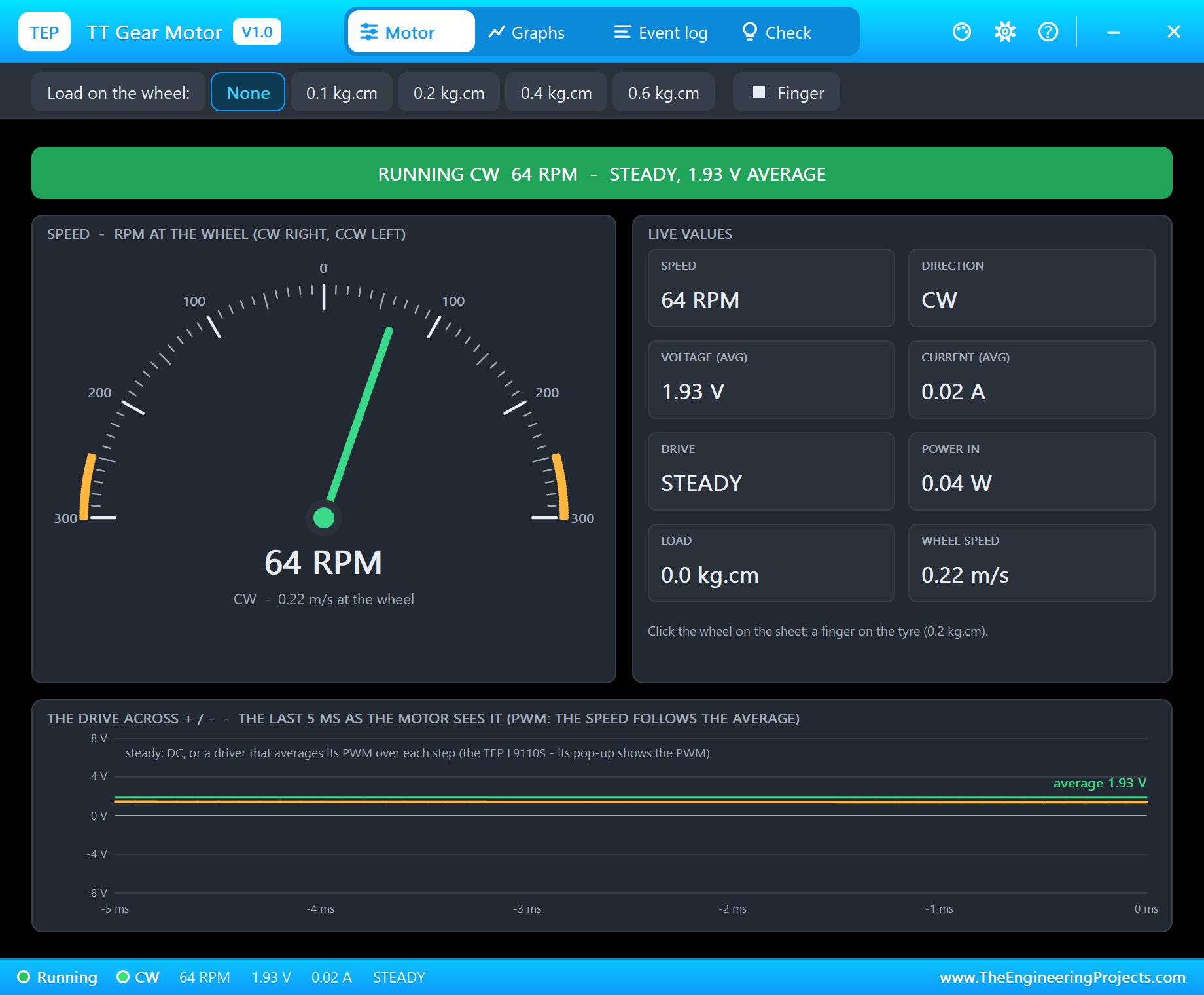
At 3 s the UNO stops both: bridge A with both inputs high (brake), bridge B with both low (coast). 0.1 s later motor A's pop-up reads 0 RPM: the motor, shorted through the low sides, braked itself to a stop in a tenth of a second. Motor B is still turning at 64 RPM, and its back-EMF, 1.41 V, shows across the open bridge. The Event log keeps both rows, BRAKE for A and COAST for B.
Straight into Reverse: the Over-Current Protection
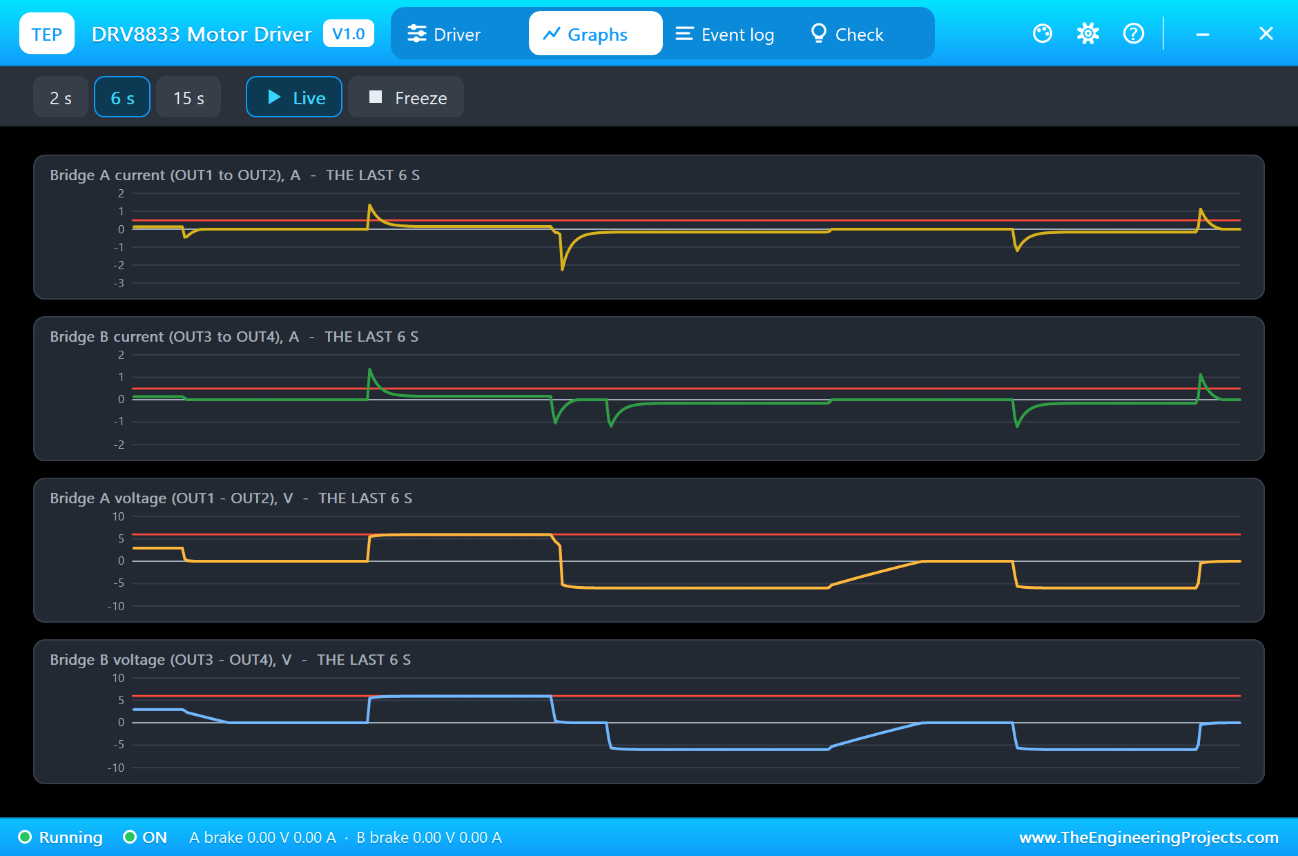
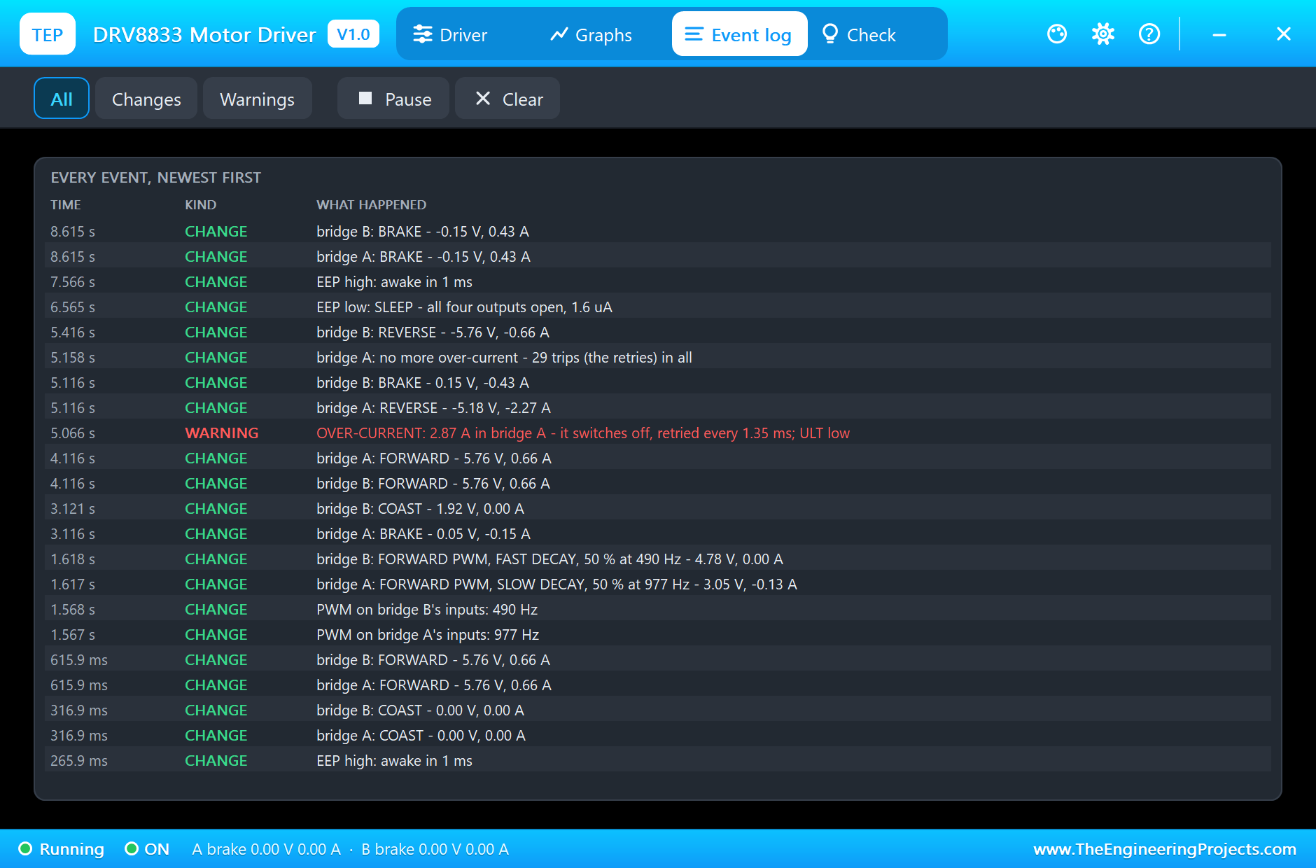
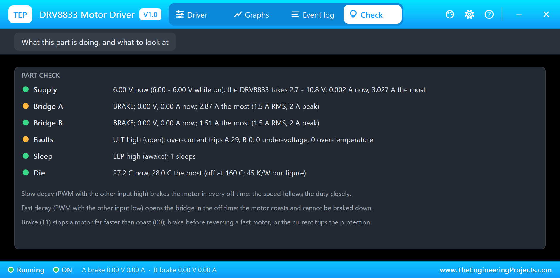
At 4 s both motors run forward at full speed again, and at 5 s the UNO does what a careless sketch does: it sends motor A straight into reverse. For an instant the motor's back-EMF adds to the supply, and the current jumps to 2.87 A, over the DRV8833's over-current threshold (2 to 3.3 A in the datasheet, 2.6 A in our model). The banner turns red, FAULT, the OVER-CURRENT A flag lights and ULT goes low. The chip switches the bridge off, waits 1.35 ms and tries again; at 5.08 s it has retried 10 times, and motor A is still turning forward at 227 RPM.
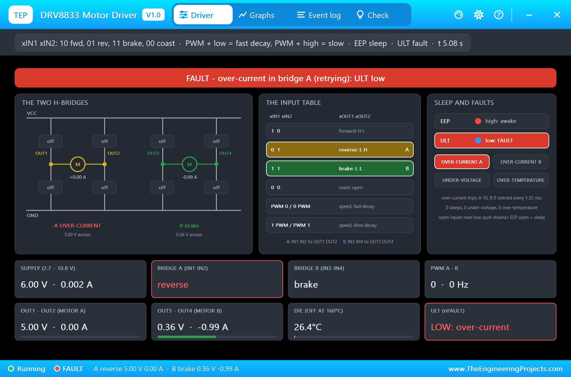
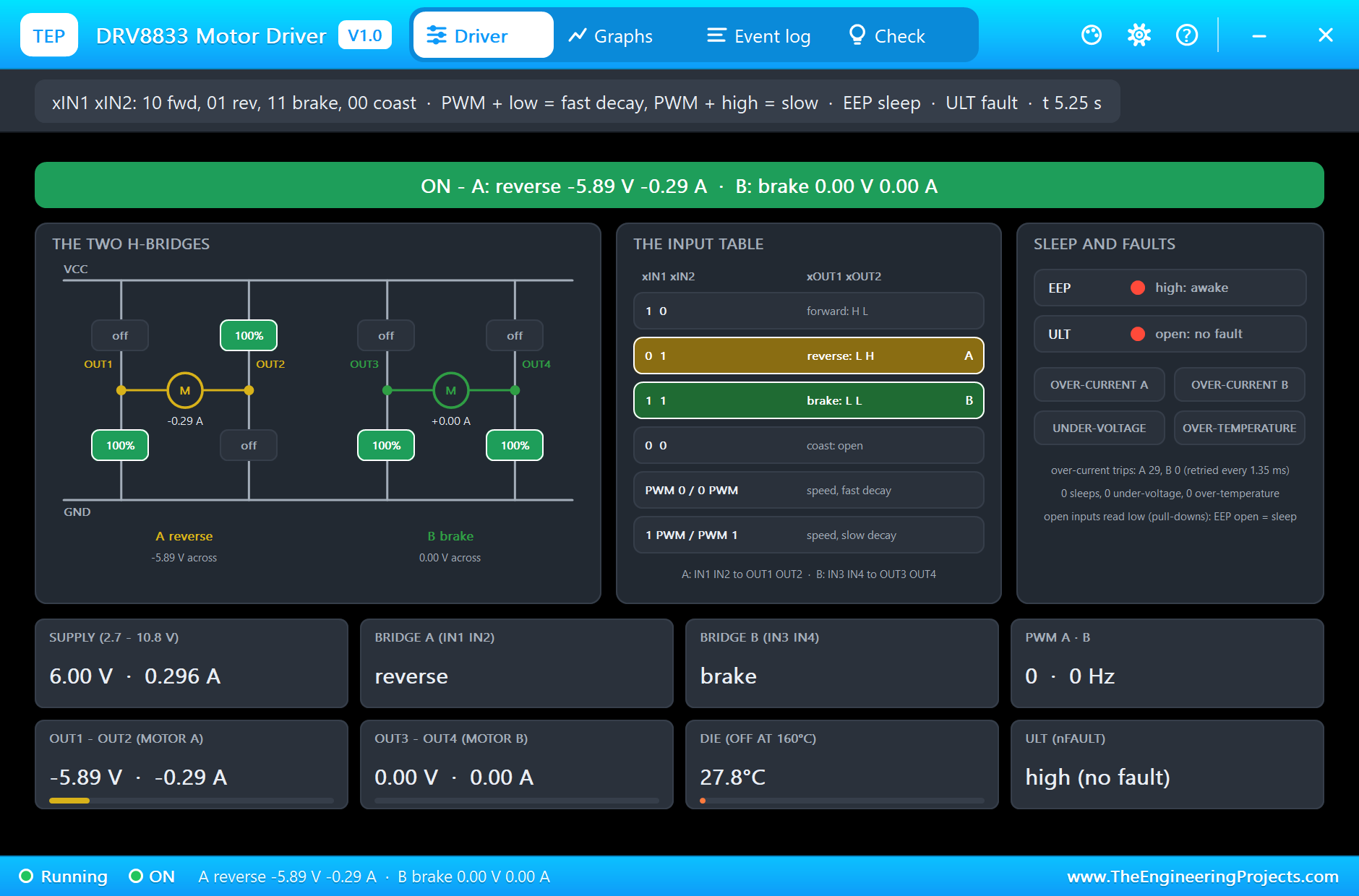
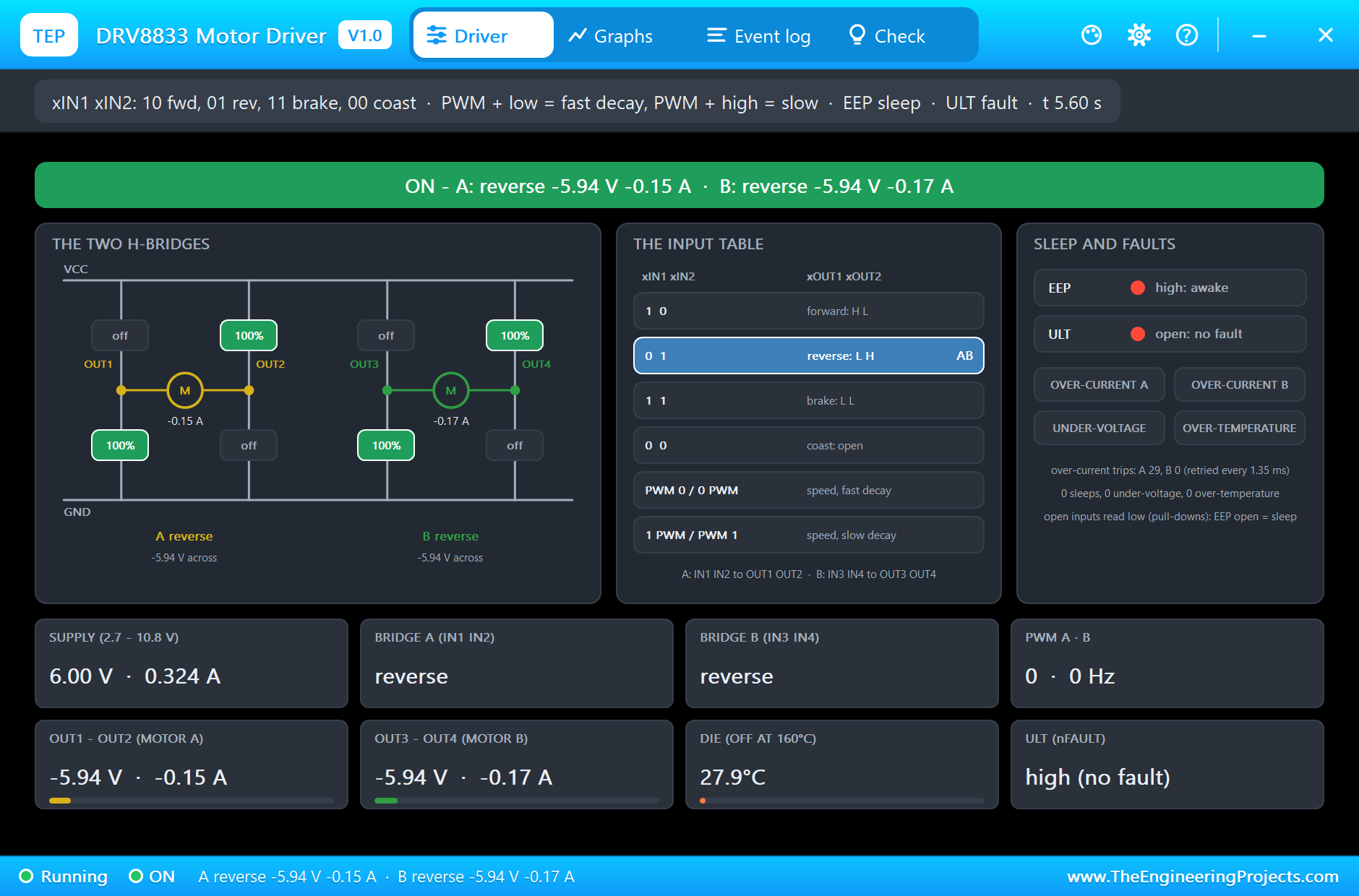
Motor B is handled the right way: braked first. In the same picture its bridge carries -0.99 A of braking current, well under the limit, with its motor at 178 RPM and slowing. Bridge A keeps retrying until its motor has slowed enough: 29 trips in about 50 ms, then it reverses, -2.27 A at first, and at 5.25 s it runs in reverse with -5.89 V and -0.29 A while B is stopped. At 5.3 s B reverses too, without a single trip, and at 5.6 s both motors run in reverse, 245 and 243 RPM. The sketch saw it as well: its monitor shows ULT low and then high again 50 ms later.
Sleep
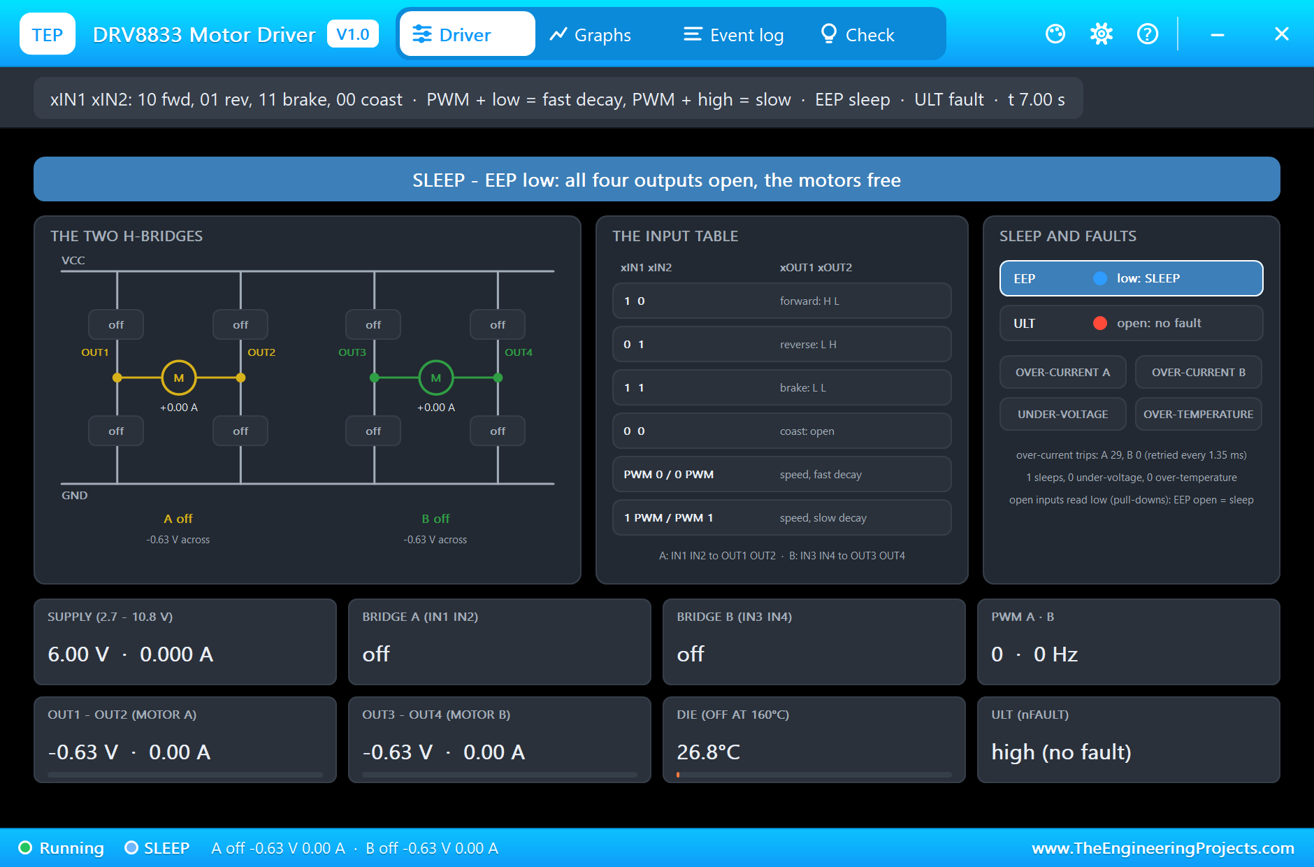
At 6.5 s EEP goes low. The banner turns blue, SLEEP: all four outputs open, both bridges off, the supply current down to the chip's microamperes, and at 7 s the two motors coast with -0.63 V of back-EMF left across them. At 7.5 s EEP goes high again; after its 1 ms wake-up the chip drives the reverse row again, and at 8.5 s both motors are braked.
The Graphs, the Event Log and the Check Page
The Graphs page plots both bridge currents and voltages over the last 2, 6 or 15 simulated seconds; the reversal shows as a spike in bridge A. The Event log keeps every mode with its voltage and current, the over-current warning at 2.87 A and the line that counts the 29 retries, and the sleep. The Check page marks the over-current trips and bridge A's peak in amber.
Try It Yourself
- Type
a 100andb 100: slow decay on both; then change the sketch's drive() call for B to fast decay and compare the slow-down again. - Type
xandcwhile both run: the brake and the coast, side by side. - Reverse motor B straight from full speed too: two bridges retrying at once.
- Raise VCC to 9 V: faster motors, and a bigger current on the reversal.
- Leave EEP unconnected: the chip sleeps and nothing turns.
Ideas to Extend the Demo
- Add a slow ramp to every reversal, so the current never reaches the limit.
- Use ULT to stop the robot and report the fault.
- Drive one small bipolar stepper from the two bridges instead of two DC motors.
Your Own Sketches
The demo sketch is in the zip file, and you can change it in the Arduino IDE. New to Arduino? Start with our Arduino Tutorial for Beginners. Export the compiled binary, and set the UNO's PROGRAM property to the new file. Our guide on How to get the HEX file from Arduino shows you where the file ends up.
Things to Know Before Using a Real DRV8833 Module
- Mind the voltage: 10.8 V is the limit; two Li-ion cells or four AA cells are fine, 12 V is not.
- Tie EEP high: or drive it from a pin; on many modules it is the chip's sleep input.
- Brake before reversing: a fast motor sent straight into reverse draws the supply plus its back-EMF.
- Invert the duty in slow decay: with xIN1 high, a larger PWM on xIN2 means a slower motor.
Troubleshooting
- SLEEP: EEP is low or not connected.
- A motor does not turn: both its inputs are low (coast) or high (brake), or the motor is not on its two outputs.
- ULT low: an over-current (it blinks while the chip retries), over-temperature or under-voltage.
- The speed is backwards: slow decay inverts the duty; see the drive() function above.
- The part is not simulated:
TEPDRV8833.DLLis missing from MODELS and from the project folder.
Limitations of the Simulation
- The PWM is averaged: in fast decay at the UNO's PWM frequencies a real motor's current also stops in each off time, so a lightly loaded motor runs faster than here.
- The current regulation through the sense pins (grounded on this module), the dead time and the switching ripple are not modelled.
- The thermal figures (45 K/W, 0.05 J/K) and the 2.6 A over-current threshold inside the datasheet's 2 to 3.3 A are our choices.
- Arduino is a name of Arduino; this library is not made or endorsed by Arduino, Labcenter, Texas Instruments or any module maker.
- Tested in Proteus 8.5 in November 2026 (the demo as shipped). Proteus 7 is not supported.
So, that was all about the DRV8833 Motor Driver Library for Proteus Simulation. I hope it helps you see in a simulation what the four rows of the input table really do to a motor: slow decay against fast decay, brake against coast, and why a reversal needs a brake first, with a pop-up that shows every switch, the input table and the fault pin. If you have any questions, ask in the comments and I will help you out. Till the next tutorial, take care and have fun!