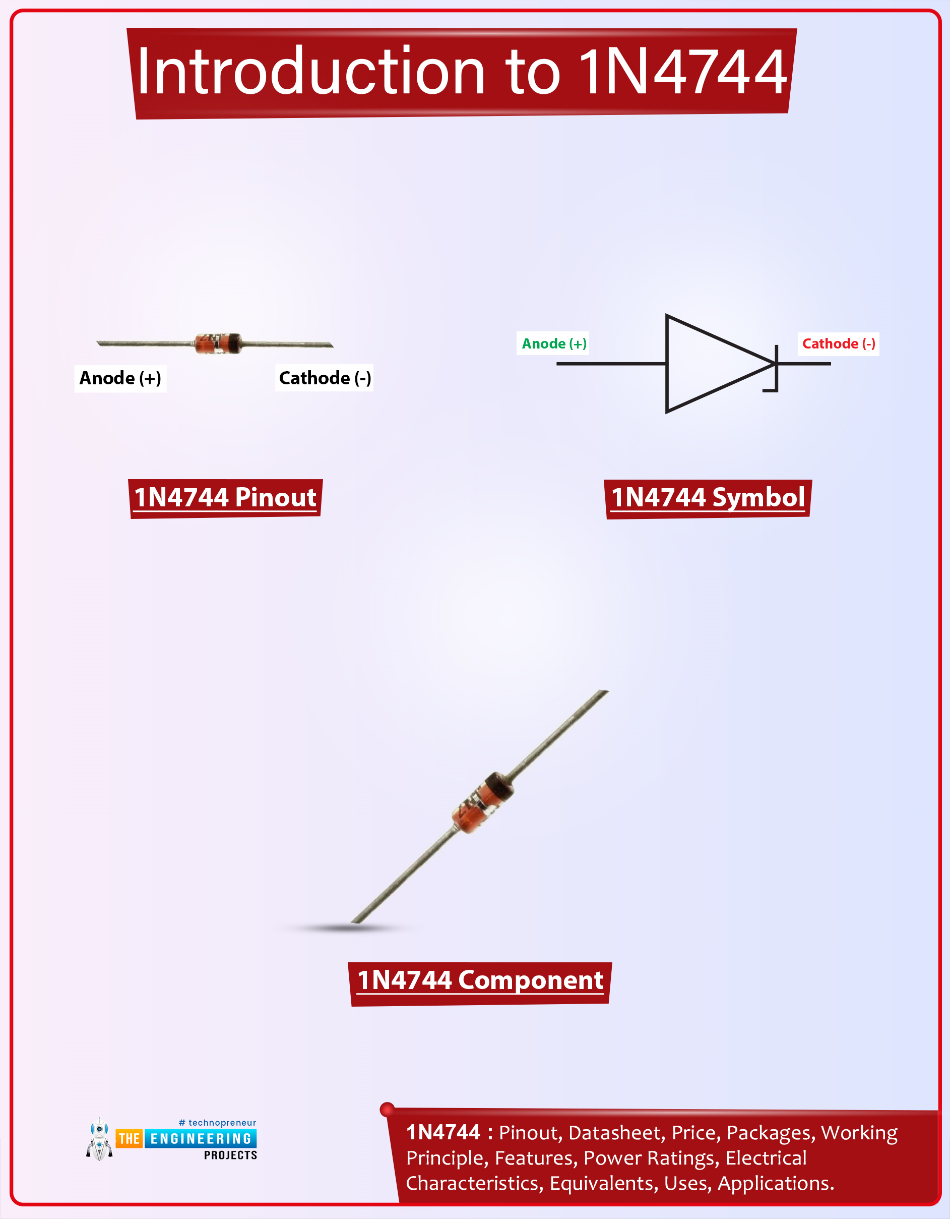
Hello Guys! I welcome you on board. In this post today, I’ll document the detailed Introduction to 1n4744.
The 1n4744 is a Zener diode that comes with a total power dissipation of 1W. It is used in high-power rating circuits for clipping purposes. This component is composed of silicon material and comes with a forward voltage drop of 1.2V. This Zener diode is a bit different than a regular diode in terms of current conduction. The 1n4744 conducts in both directions i.e. forward-biased and reverse-biased conditions. While the regular diode conducts in forward-biased condition only. Zener diodes are also employed to prevent the electrical circuits from overvoltage.
Read the entire post as I’ll detail the datasheet, pinout, features, and applications of 1n4744. Keep reading.
Introduc ...
Hello everyone! I hope you all will be absolutely fine and having fun. Today, I am going to share my knowledge about Introduction to TL072. TL 072 is basically a high speed Junction Field Effect Transistor (JFET). It is also known as the dual operational amplifier. It has a bipolar transistor and high voltage JFET in its case. TL-072's important features include low offset current, high slew rates, low input voltage, low offset temperature coefficient etc.
Some of the major features may include low power consumption, low noise, common mode input voltage range includes Vcc, latch-up free operation etc. TL 072 has a very wide range of applications including oscilloscope, solar inverters, AC inverters and VF drives, audio mixers, Un-interruptable Pow ...
Hey pals! I wish you are doing great. Welcome to a new lesson about the Digital Logic Circuits in The Engineering Projects. In the past tutorials, we Designed the Basic JK Flip Flop. Today, we'll talk about the following Points:
What are JK Flip Flops?
What are the Master Slave Flip Flops?
How does the Circuit of Master Slave Flip Flop looks?
How types of JK Flip Flop different from each other?
How does the simulation of Master JK Flip Flip take place in Proteus ISIS?
Moreover, we'll also learn some key concepts in DID YOU KNOW portions. Yet Let's recall some points about the topic. Flip Flops are the building block of a huge number of electronic systems and devices. A Flip Flop is a Digital circuit that can take the bits as input, wor ...
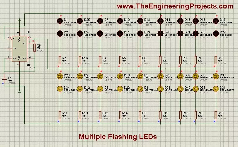
Hello friends, hope you all are enjoying and having fun. In today's tutorial, we are gonna see How to design a Multiple LED Flasher Project using 555 Timer in Proteus ISIS. In our previous tutorial we have seen How to design a LED Flasher Project with 555 Timer in Proteus ISIS, in which we have flashed single and double LEDs. In today's post, I am gonna extend that previous tutorial and will see How to flash multiple LEDs with 555 Timer in Proteus ISIS.
Its quite a quick tutorial, as I don't have much material on it and its also quite simple so no much explanation is required. The complete project is given at the end for download but again as I always mention, try to design it by yourself, so that you get some knowledge out of it.This type of proj ...
Hello readers, I hope you all are doing great. In this tutorial, we will learn how to interface the BMP280 sensor with the ES32 module to get temperature, pressure and altitude readings. Later, in this tutorial, we will also discuss how to upload these sensor readings to a web server.
BMP280
BMP280 or Barometric pressure sensor is a module used to measure temperature pressure and altitude. The small size and low power consumption feature of this sensor makes it feasible for battery-powered devices, GPS modules and mobile applications etc.
Fig. 1 BMP280 Sensor
The BMP280 is the product of BOSCH which is based on Bosch’s proven Piezo-resistive pressure sensor technology featured with high accuracy, long term stability, linearity and high EMC robus ...
In the previous post we have seen the project description of Voice Recognition Project using EasyVR shield. Today we will have a look at Getting started with EasyVR commander. EasyVR shield is a module which is used for voice recognition. First of all, we save our commands in the EasyVR shield and then we use these commands to control anything. In this project, I need to control the robot with voice commands like when someone says FORWARD then the robot start moving in forward direction.
Now first of all what I need to do is to save this FORWARD voice in the shield, which we will see today how to save the command in the shield and after that I will show you the Interfacing of EasyVR shield with Arduino UNO. So that when I say Forward the motor sta ...
Hello geeks, I hope you all are doing well and looking forward to making something new yet interesting. So, today we have come up with our new project which is a calculator using Arduino.
We all use calculators in our daily life, whether you are working in an office or counting money at the bank, you are buying your daily grocery or doing shopping online, you will find calculators in different forms everywhere. In fact, the computer was initially considered a giant calculator. So if it is that common, why do we not make our own calculator?
Before going into the details of the project, it is good to know some history of that, let’s know some facts about the calculator. So the first known device for calculation is Abacus. And the first digital calcu ...
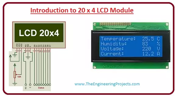
Hello friends, I hope you all are doing great. In today’s tutorial, we will have a look at the Introduction to 20x4 LCD Module. The LCD stands for liquid crystal display, which works on the light modulation features of liquid crystals. It is available in electronic visible display, video display and flat panel display. There are numerous categories and features are exist in markets of LCD and you can see it on your mobile, laptop, computer and television screen.
The invention of LCD gives new life to electronic industries and replaces lED and gas plasma techniques. It also replaces the CTR (cathode ray) tube that is used for visual display. The input power consumed by the liquid crystal display is less than the light-emitting diode and plasma display. In today's post, we will have a loo ...
Hello Pupils! I welcome you to the board. I hope you are fine. In today's tutorial, we will design a project Metal Detector using 555 Timer in Proteus ISIS. All of us perceive the situations when at the public places such as on airports or in shopping malls where sharp metallic objects such as a knife or illegal guns or even a nail cutter are not allowed, there are walkthrough gates at every entrance so that any person with the forbidden material when passes through the gate, the alarming buzzer automatically switched on. This happened because the walkthrough gates have the Metal Detector circuit in them that works immediately when such a situation occurs.
In this session, we'll learn:
What are Metal Detectors?
How does the 555 Timer collabor ...
Hello everyone! I hope you all will be absolutely fine and having fun. Today I am going to given elaboration on Introduction to L293D. L 293D is basically a high current dual motor driver/controller Integrated Circuit (IC). It is able to drive load having current up to 1A at the voltage ranging from 4.5V to 36V. Motor driver usually act as current amplifier because they receive a low current signal as an input and provides high current signal at the output.
Motors usually operates on this higher current. L-293D has to builtin H-Bridge driver circuits and is able to control two DC motors at a time in both clockwise and counter clockwise direction. It has two enable pins and they should be kept high in order to control the motor. By changing the p ...