… it with LCD in the Proteus workspace. Arduino Nano LCD Interfacing I’ll interface 20x4 LCD with the Arduino Nano. Design the circuit below to interface LCD with Arduino Nano: Pins 8,9,10 & 11 of Arduino Nano are connected to the data pins of LCD, while Enable …
… the BUZZER, which is an output component. LCD 20×4 is used and lcd.begin is used to initiate the LCD. lcd.setCursor is used to cursor position on LCD and the name of the project is displayed on LCD Screen using lcd.print command. Now, let's run our simulation …
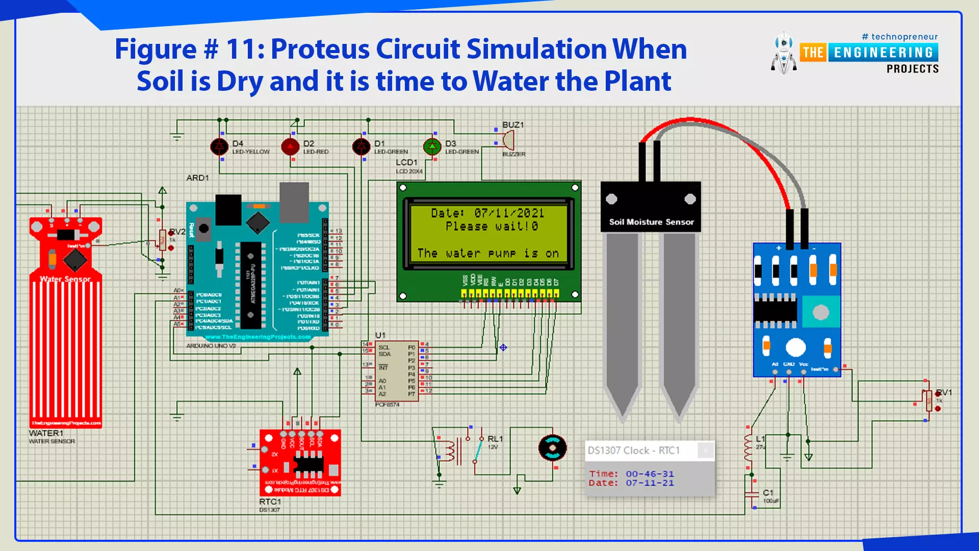
… objects being defined are the RTC module and LCD. In the syntax below we used 20x0 in the argument for the LCD, that is because there are no libraries for I2C LCDs and we had to turn a simple LCD into an I2C LCD by the means of PCF8574. Figure # 16: Arduino …
… LCD with the Arduino board. You’ll get the following circuit as you interface LCD with the Arduino Nano board: Data pins of LCD are attached with 8,9,10 & 11 pins of Arduino Nano, while 12 & 13 Pins of Arduino board are attached to Enable and reset of LCD. …
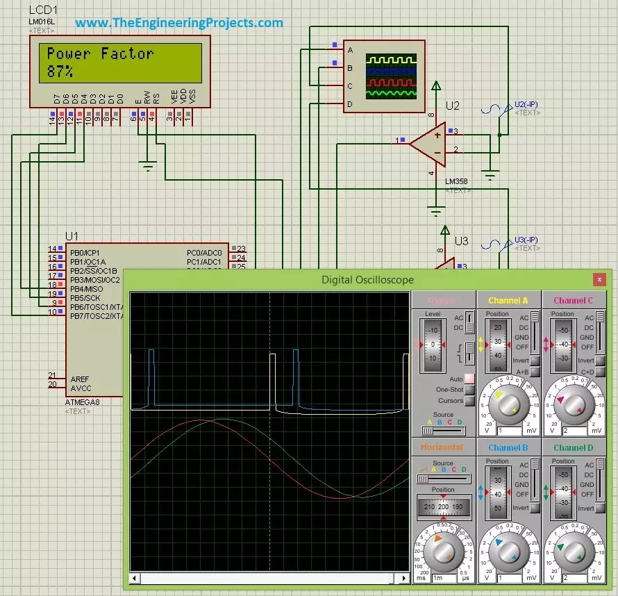
… timing difference between voltage and current can be converted into a phase angle, and then into a power factor reading on an LCD. I will start with the electrical meaning of power factor, because a correct calculation is useful only when we understand what it …
… with a 20x4 LCD. Design the circuit given below and interface LCD with the Arduino Mini board: Data pins of LCD are connected with 8,9,10 & 11 pins of Arduino Mini, while Pin 12 & 13 of Arduino board are connected to Enable & Reset of LCD. To upload the code, …
… a 20x4 LCD with the Arduino Pro Mini board. Design the circuit as shown below to interface the LCD with the Arduino Pro Mini: The data pins of the LCD are attached with pins 8,9,10 & 11 of Arduino Pro Mini while Enable & Reset of LCD are attached to Pin 12 & …