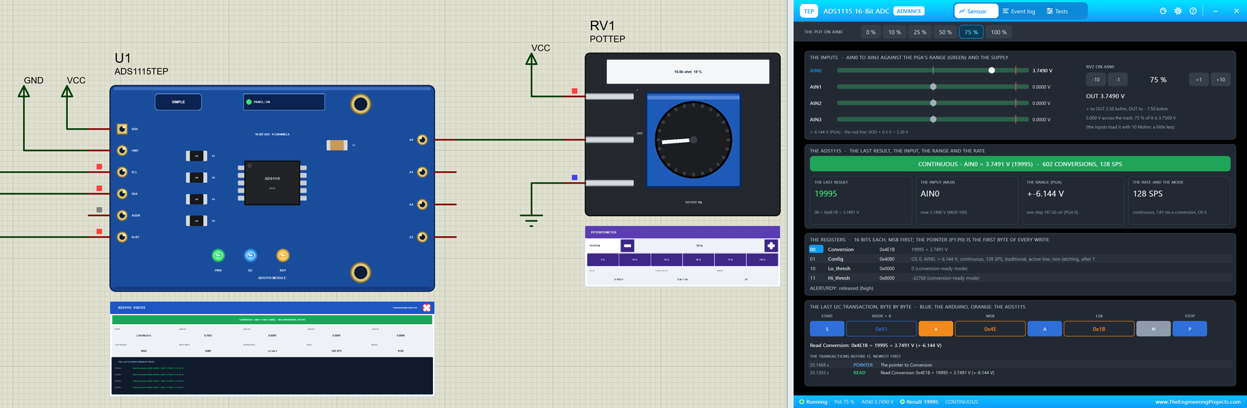
Hello friends, I hope you all are doing great. Today, I am going to share the new ADS1115 ADC Library for Proteus V1.0 . The ADS1115 is the 16-bit analog-to-digital converter that Arduino makers add when the UNO's own 10-bit ADC is not enough: four inputs, a programmable gain amplifier that can read a few millivolts, and an I2C bus. It sits in weighing scales, battery testers, soil and gas sensor boards, heart-rate monitors and data loggers. Now you can build and test those projects in Proteus, with the blue ADS1115 module and a 10 kohm potentiometer to turn. Updates ADS1115 ADC Library for Proteus Latest version: V1.0 (October 2026, this tutorial) Other measurement modules: INA219 · Current Sensor WCS1600 · HX711 Load Cell Helping Tools Serial Monitor Advance : a serial terminal window fo ...
A lot of engineering students know this feeling. The code uploads without any error, the laptop says everything is fine, and then the actual project does almost nothing. The motor does not spin. The sensor value jumps around. The board resets for no clear reason. That is usually when the real lesson starts. Good engineering is not only about writing code. It is also important to know what the circuit is doing when the code reaches the board. Code Can Look Right While the Hardware Fails Most small engineering projects need code now. Arduino, Raspberry Pi, ESP32, and STM32 boards all depend on it. But the code is only one part of the project. Once it reaches the board, the wiring, power, and parts all have a say too. A student may spend an hour changing a program when the real issue is a wea ...
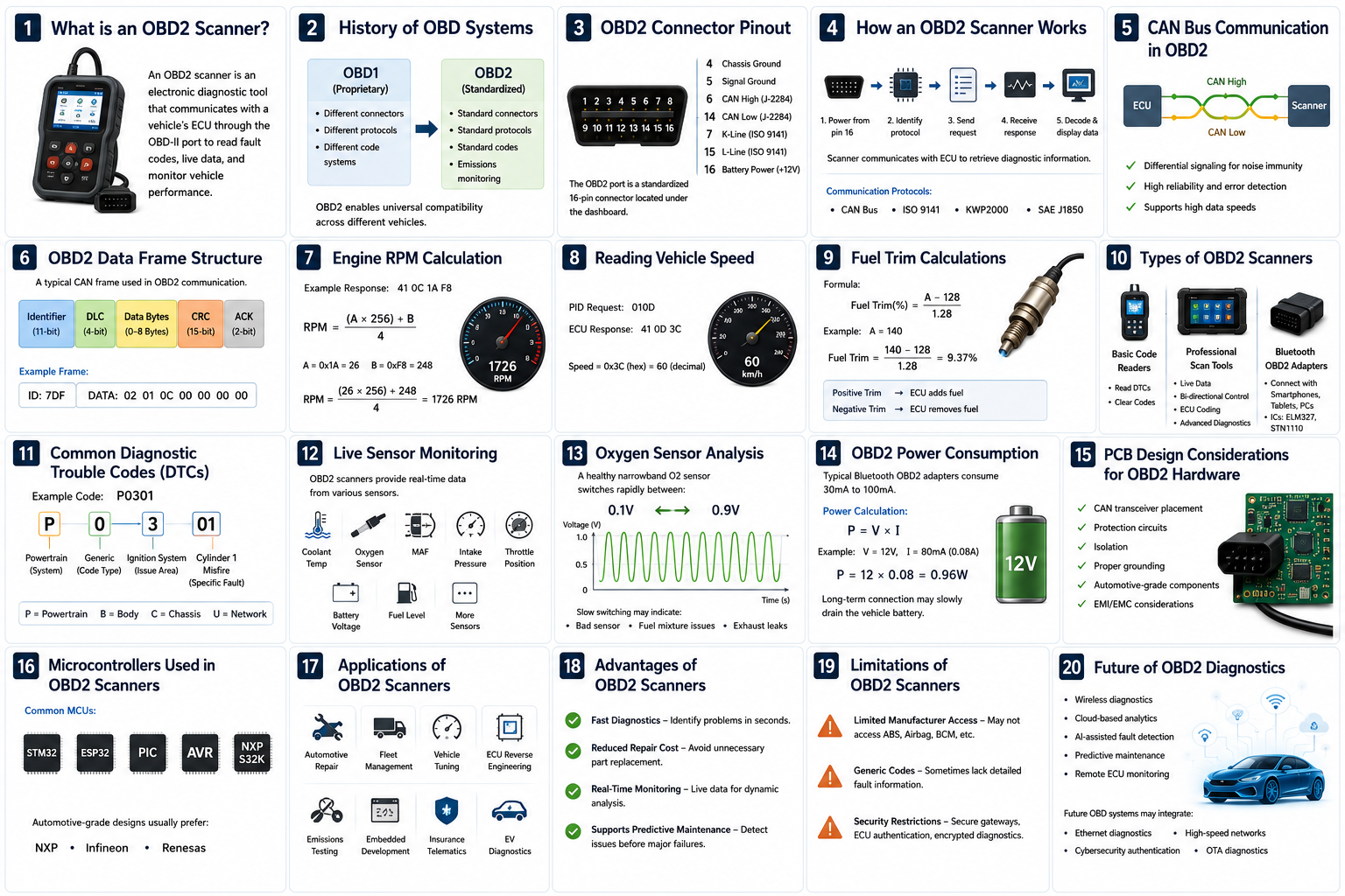
Modern vehicles are no longer just mechanical machines. Today’s cars contain dozens of Electronic Control Units (ECUs), sensors, communication buses, and embedded systems working together in real time. Whenever a fault occurs, these systems generate Diagnostic Trouble Codes (DTCs), and this is where an OBD2 scanner becomes an essential tool. Whether you are an automotive engineer, embedded developer, mechanic, or electronics hobbyist, understanding how OBD2 scanners work gives you deep insight into vehicle diagnostics, CAN communication, and automotive electronics. What is an OBD2 Scanner? An OBD2 scanner is an electronic diagnostic tool used to communicate with a vehicle’s onboard computer system through the OBD-II (On-Board Diagnostics) port. It allows us to: Read Diagnostic Trouble Code ...
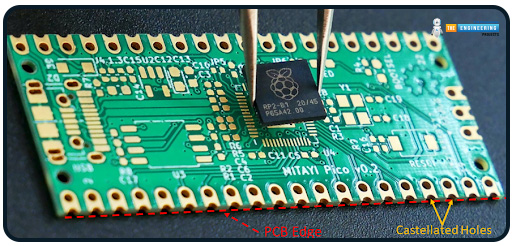
Hi readers! I hope you are having a great day and finding something new to learn. Today, the topic of our discourse is PCB Castellation and Castellated Holes. Printed Circuit Boards (PCBs) are the core of nearly all electronic devices and are a structured platform on which components are mounted and interconnected. As electronics are moving toward more miniaturization, modularization, and mass production, PCB technologies must advance to be able to support these new requirements. Part of this advancement is the use of PCB castellations or castellated holes, a technology that supports small, modular board-to-board connections. Castellated holes are tiny, plated half-holes on the border of a PCB. They allow one PCB, a module, or daughterboard, to be soldered onto another directly, much like ...
Hi learners! I hope you are doing great. Today, I am going to share the second version(V2.0) of the LCD library for Proteus. We have already shared the LCD V1.0 Library on our blog. Along with appreciation, we also get some complaints/suggestions about that library. So, we have designed a better version of the LCD library by keeping the suggestions in mind. Updates LCD Library for Proteus Latest version: LCD Library for Proteus V3.0 (October 2026): LCD 16x2, LCD 20x4 and both I2C LCDs in one library, with our own HD44780 model and an Arduino demo Earlier versions: V2.0 (2023, this tutorial) · V1.0 (2016) One LCD only? LCD 16x2 · LCD 20x4 · I2C LCD 16x2 · I2C LCD 20x4 Helping Tools Serial Monitor Advance : a serial terminal window for the UART of your board Serial Monitor Expert : the seria ...
PWM stands for P ulse- W idth M odulation. Once the switching frequency (f sw ) has been chosen, the ratio between the switch-on time (T ON ) and the switch-off time (T OFF ) is varied. This is commonly called duty-cycle (D). The duty cycle can be between 0 and 1 and is generally expressed as a percentage (%). D = T ON / (T ON + T OFF ) = T ON x f sw The variation of the pulse width, made at a high frequency (kHz), is perceived as continuous and can be translated into a variation of the rotation speed of a motor, dimming a LED, driving an encoder, driving power conversion, and etc. The use of PWM is also widely used in the automotive sector in electronic control units (ECU - Electronic Control Unit) to manage the energy to be supplied to some actuators, both fixed and variable frequency. A ...
A D igital to A nalog C onverter( DAC ) performs the task of converting digital words of n bits into voltages whose amplitude will be proportional to the value of the code expressed by the words themselves. Since the input binary words represent a succession of finite codes, the voltage coming out of a DAC cannot be continuous over time but is made up of as many levels as the converted codes are. This means that the devices to which the analog signal produced by a DAC is sent must filter it with a low-pass characteristic (integrating action). The operating criterion of a DAC is simple: in fact, it is sufficient to have a succession of as many voltages as there are convertible codes, obtained for example by means of a weighted resistance network (i.e. the value proportional to the code impl ...
An A nalog to D igital C onverter ( ADC ) converts a continuous signal (usually a voltage) into a series of discrete values ??(sequences of bits). The main features are: Resolution (in analog terms): It is the minimum variation of the analog input voltage that can determine the variation of the LSB, that is of the least significant bit of the output code. Since the quantization step Q corresponds to the LSB, it can be said that the resolution coincides with the quantization step Q (and therefore is measured in Volts). We can say that the quantization step Q corresponds to the LSB because two contiguous quantization bands, each of amplitude Q, are identified by codes that differ only for the least significant bit. Resolution (in digital terms): It is the number n of bits present at the conv ...
The SPI ( S erial P eripheral I nterface) protocol, or rather the SPI interface, was originally devised by Motorola (now Freescale) to support their microprocessors and microcontrollers. Unlike the I2C standard designed by Philips, the SPI interface has never been standardized; nevertheless, it has become a de-facto standard. National Semiconductor has developed a variant of the SPI under the name Microwire bus. The lack of official rules has led to the addition of many features and options that must be appropriately selected and set in order to allow proper communication between the various interconnected devices. The SPI interface describes a single Master single Slave communication and is of the synchronous and full-duplex type. The clock is transmitted with a dedicated line (not necess ...
EEPROMs ( E lectrically E rasable P rogrammable R ead- O nly M emories) allow the non-volatile storage of application data or the storage of small amounts of data in the event of a power failure. Using external memories that allow you to add storage capacity for all those applications that require data recording. We can choose many types of memories depending on the type of interface and their capacity. EEPROMs are generally classified and identified based on the type of serial bus they use. The first two digits of the code identify the serial bus used: Parallel: 28 (for example 28C512) much used in the past but now too large due to having many dedicated pins for parallel transmission Serial I2C: 24 (for example 24LC256) Serial SPI: 25 (for example 25AA080A) Serial - Microwire: 93 (for exa ...