Hello friends, I hope you all are doing great. Today, I am going to share the new MAX30205 Body Temperature Sensor Library for Proteus, the fourth of the biomedical set in our University Lab series. The MAX30205 is a small digital temperature sensor made for the human body: it reads 0.1 °C accurate between 37 and 39 °C, gives 16-bit results over I2C and has its own alarm output. It is the chip inside many wearable thermometers, fever patches and fitness bands, and it is a favourite in biomedical student projects because it turns a body temperature into a clean number with only two wires.
MAX30205 Body Temperature Sensor Library for Proteus
Latest version: V1.0 (November 2026, this tutorial)
Other component libraries: C945 Transistor · PC817 Optocoupler · Relay Module · Resistor · 5 mm LED · Designer Colour LED · Push Button · Active Buzzer · Electrolytic Capacitor · Ceramic Capacitor · Tantalum Capacitor · Film Capacitor · 1N4007 Diode · Zener Diode · Schottky Diode · Supercapacitor · Photodiode · RGB LED · Bridge Rectifier · Flashing LED · Bi-Colour LED · SMD LED · Slide Switch · Toggle Switch · Rocker Switch · Micro Limit Switch · Emergency Stop Switch · SMD Resistor · Power Resistor · Resistor Network · Potentiometer · Trimmer Potentiometer · Slide Potentiometer · NTC Thermistor · DIP Switch · Fuse · Passive Buzzer · Mini Speaker · 7-Segment Display · LED Bar Graph · IR / UV LED · Small Transistors · TIP122 Darlington · N-MOSFET · P-MOSFET · PC817 Optocoupler · Filament Bulb · Power LED · Voltage Regulator · SCR and TRIAC · Inductor · Toroid Inductor · Crystal · Temperature Control Lab · DC Servo Lab · Ball and Beam · Magnetic Levitation · Rotary Pendulum · Coupled Tanks · AD8232 ECG · MyoWare EMG · GSR Sensor · MCP4725 · MCP3008 · LM358 · NE555 Timer · INA128 · 74HC595
Helping Tools
- Serial Monitor Advance: a serial terminal window for the UART of your board
- Serial Monitor Expert: the serial monitor with extra debugging tools
- LCD Library for Proteus V3.0: 16x2, 20x4 and I2C LCDs to show your readings
Our library brings it into Proteus on a small breakout board drawn at its true size, 20 x 15 mm. Every register, every bit of the configuration, the conversion timing, both data formats and the alarm output in both of its modes follow the datasheet, so the code you write in Proteus is the code that runs on the real chip. The skin under the sensor follows a temperature profile you write in a property, and the chip warms up to it the way a real one does, through its pad. The pop-up shows the sensor on a forearm, a thermometer with the alarm limits and the whole run. The demo is an Arduino that sets a fever alarm over I2C and watches it trip and clear.
NOTICE: Our team has put a lot of effort into these small parts: the bodies, the animation and the pop-ups are all our own design, and you get them free. Your feedback is the fuel that keeps us going, so please tell us what you think in the comments below or in the MAX30205 board of our forum. And if our free libraries help you, you can buy us a coffee. So, let's get started with the MAX30205 Body Temperature Sensor Library for Proteus:
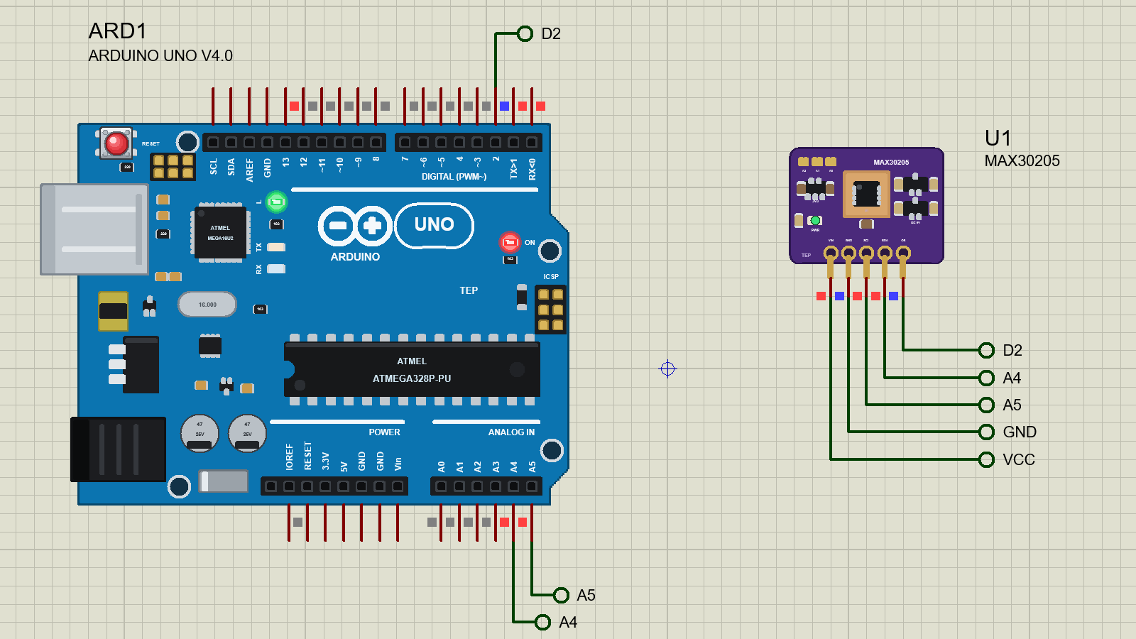
What is the MAX30205?
The MAX30205 is a human body temperature sensor from Maxim Integrated, now part of Analog Devices. Inside its 3 x 3 mm TDFN package there is a temperature sensor, a high-resolution sigma-delta converter, an I2C interface and a digital comparator that drives an open-drain alarm pin called OS. Its datasheet says it meets the clinical thermometry specification ASTM E1112 when it is soldered on its final board.
| MAX30205 | |
|---|---|
| Accuracy | 0.1 °C from 37 to 39 °C; 0.2 to 0.5 °C outside that, over 0 to 50 °C |
| Resolution | 16 bits, 0.00390625 °C (1/256 °C) |
| Conversion | 44 ms typical, 50 ms maximum; the first result 50 ms after power-on |
| Supply | 2.7 V to 3.3 V, 600 uA typical, 3.5 uA maximum in shutdown |
| Interface | I2C up to 400 kHz, 32 addresses, a 50 ms bus timeout |
| Alarm | OS, open-drain: comparator or interrupt, active low or high, fault queue 1, 2, 4 or 6 |
| Package | 8-pin TDFN, 3 x 3 mm, with an exposed pad |
The Accuracy Bands
The datasheet does not give one accuracy for the whole range. It is best where a body lives: plus or minus 0.1 °C from 37 to 39 °C, 0.2 °C just below and above that band, 0.3 °C from 15 to 35.8 °C and from 41 to 45 °C, and 0.5 °C at the ends of the 0 to 50 °C range. That is exactly what a fever thermometer needs: the most precise readings right around the line between normal and fever. The ADC is also very repeatable, 0.009 °C (one sigma) from one reading to the next.
It Measures Its Own Die
This is the most important thing to understand about any contact temperature sensor. The MAX30205 measures the temperature of its own silicon die. Heat reaches the die mainly through the leads and the exposed pad, so the chip really measures the board it is soldered on. To measure the body, the side with the pad goes against the skin, the rest is insulated from the air, and then you wait for the heat to come through. On a real patch that takes minutes. In our model the die starts at the air temperature and, once the sensor is worn, follows the skin with a time constant you choose; the demo uses 2 seconds so the whole story fits in a short run.
This is not a medical device. The library is for learning how body temperature sensors work and for building projects; never use it for diagnosis.
The Registers
The chip has four 16-bit registers, chosen by a pointer byte that the master writes after the address. The pointer moves on by itself after every two data bytes, but it does not wrap from the last register back to the first.
| Pointer | Register | At power-on | Access |
|---|---|---|---|
| 00h | Temperature | 0000h | read-only |
| 01h | Configuration | 00h | read / write |
| 02h | THYST | 4B00h = 75 °C | read / write |
| 03h | TOS | 5000h = 80 °C | read / write |
The temperature, TOS and THYST registers share one format: a 16-bit two's complement number sent most significant byte first, where one step is 0.00390625 °C. In other words, divide the number by 256. 36.6 °C is about 249Ah, 38.0 °C is exactly 2600h and 37.5 °C is 2580h. The configuration register holds a single byte; read it as two bytes and you get the same byte twice. While a read is in progress, the chip holds the temperature register still, so the two bytes always belong together.
The Configuration Byte
| Bit | Name | What it does |
|---|---|---|
| D7 | ONE-SHOT | in shutdown, 1 starts a single conversion; it returns to 0 when the conversion is done |
| D6 | TIMEOUT | 0: the interface resets if SDA is held low for about 50 ms; 1: no timeout |
| D5 | DATA FORMAT | 0: normal; 1: extended, the value plus 64 °C (from the next completed conversion) |
| D4, D3 | FAULT QUEUE | 1, 2, 4 or 6 conversions in a row needed to change OS |
| D2 | OS POLARITY | 0: OS active low; 1: active high |
| D1 | COMPARATOR / INTERRUPT | 0: comparator (a thermostat); 1: interrupt (latched) |
| D0 | SHUTDOWN | 1: stop converting (a conversion in progress completes first) |
The OS Alarm
OS compares every conversion with two limits. In comparator mode it works like a thermostat: it turns on when the temperature rises above TOS and turns off only when it falls below THYST. The gap between the two, the hysteresis, stops it from chattering when the temperature hovers near the limit. In interrupt mode it turns on when the temperature crosses TOS and then stays on until the master reads any register; after that it waits for the temperature to fall below THYST, turns on again, and so on. That suits a microcontroller that wants an interrupt for each crossing. The fault queue adds a filter on top: with 2, OS changes only after two conversions in a row agree.
OS is an open-drain output, so it can only pull low; a pull-up resistor gives the high level. Our board has that pull-up, and the demo also turns on the UNO's own.
Features of the MAX30205 Body Temperature Sensor Library for Proteus
- A real breakout at true scale: 20 x 15 mm with the chip on its thermal pad, a 3.3 V regulator, BSS138 level shifters, address jumpers and a PWR LED.
- The datasheet's registers: pointer rules, power-on values, the 16-bit two's complement format and the extended format.
- Real timing: 44 ms conversions, the first 50 ms after power-on, and the 0.009 °C repeatability.
- The OS alarm: comparator or interrupt, active low or high, with the fault queue.
- Shutdown and one-shot, the 50 ms bus timeout and all 32 I2C addresses.
- Thermal behaviour: the die warms from the air to the skin, and lags a changing temperature.
- A pop-up: the sensor on a forearm, a thermometer with the limits, the whole run with OS shaded, eight live values, graphs, an event log and a check page.
- A complete package: about 1.2 MB with the library, our Arduino UNO V4.0 and the demo, without the source code of the model.
The MAX30205 in Proteus
The device is MAX30205TEP in TEPMAX30205.LIB, under Biomedical, with the prefix U and the model TEPMAX30205.DLL, a mixed model: VIN and GND are analog, SCL, SDA and OS digital. Search MAX30205 in Pick Devices. The header along the bottom edge has VIN, GND, SCL, SDA and OS on the 2.54 mm pitch.
The bare chip runs from 2.7 to 3.3 V and its SDA and SCL pins must never see more than 4 V, so it cannot sit directly on a 5 V UNO. That is why our board, like most real breakouts, carries a 3.3 V regulator and two BSS138 level shifters with their pull-ups: VIN takes 3.3 to 5 V and the bus works at the host's level.
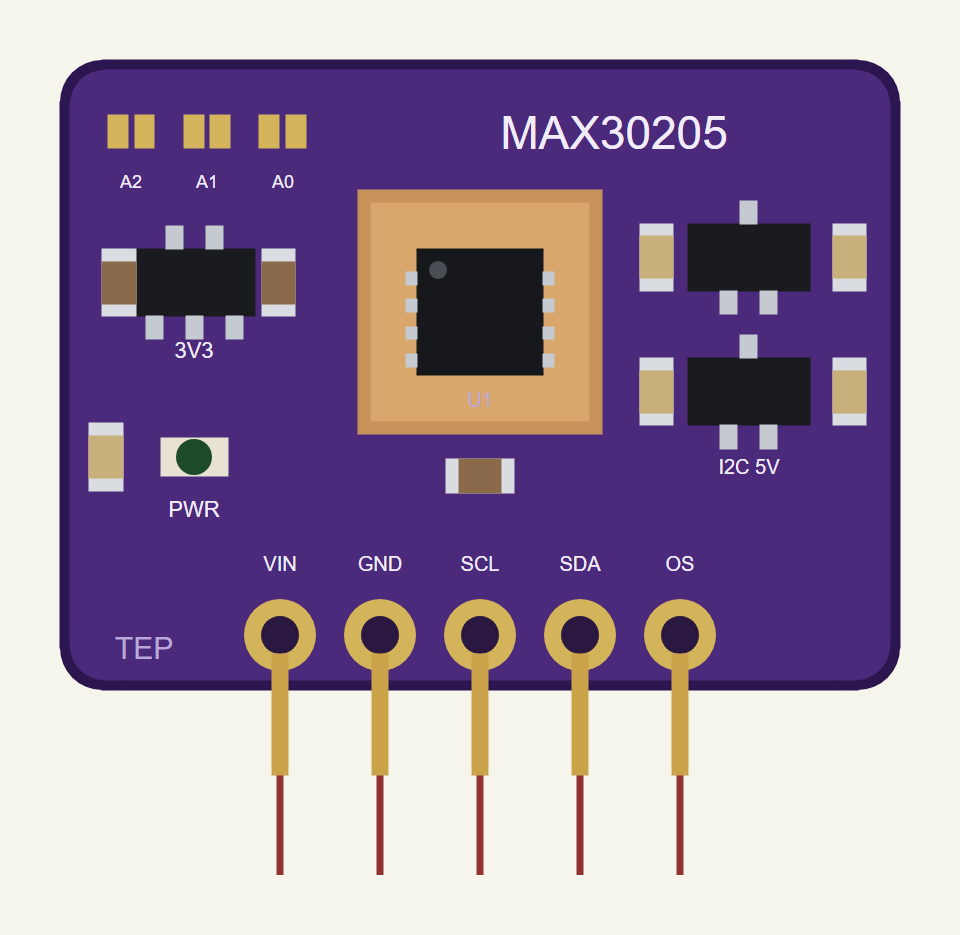
The Properties
| Property | What it does |
|---|---|
| Skin (BODY) | "time:C, ..." - the skin under the sensor, straight lines between the points |
| Air (AMB) | the temperature before the sensor is worn; 24 °C by default |
| On the skin (WEAR) | the time the sensor goes on the skin; 2 s by default |
| Time constant (TAU) | how fast the die follows the skin; 2 s by default (minutes on a real patch) |
| Address (ADDR) | the I2C address, 0x40 to 0x5F, as the A2 / A1 / A0 jumpers set it; 0x48 by default |
Download MAX30205 Body Temperature Sensor Library for Proteus
Click the button below to download MAX30205-Body-Temperature-Sensor-Library-for-Proteus-v1.0.zip (about 1.2 MB, without the source code of the models):
MAX30205 Library for Proteus V1.0- README.txt: installation, the demo, the wiring, troubleshooting and the limits.
- Proteus Library Files:
TEPMAX30205.LIBand ourArduinoV4TEP.LIB. - Proteus Model Files:
TEPMAX30205.DLLandTEPARDUINO.DLL. - Arduino Code: the demo sketch.
- Proteus Simulation: the demo project, its HEX file and copies of the DLLs.
No Proteus yet? Read How to Download and Install Proteus 7 and 8. New to libraries? Follow How to Install a New Library in Proteus.
How to Install MAX30205 Body Temperature Sensor Library for Proteus
- Close Proteus and extract the whole zip file, for example to your Desktop.
- Copy the files from Proteus Library Files into the LIBRARY folder of Proteus.
- Copy the files from Proteus Model Files into the MODELS folder.
- Delete
TEPMAX30205.IDXfrom the LIBRARY folder if it is there. - Start Proteus, press P and search for MAX30205.
Demo: A Fever Alarm over I2C
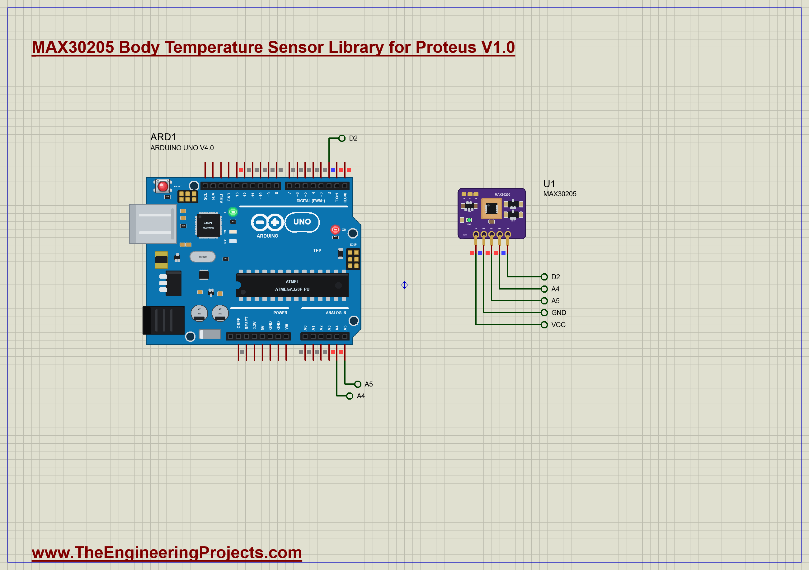
The demo is just the board and our Arduino UNO Library for Proteus V4.0, with its built-in monitor, the same window as our TEP Serial Monitor Advance for Proteus. VIN goes to the 5 V rail, SDA to A4, SCL to A5 and OS to D2. The sensor goes on the skin at 2 s. The skin is at 36.6 °C, climbs to a fever of 38.4 °C between 16 and 26 s, stays there until 32 s and falls to 37.2 °C by 42 s. Open MAX30205-Temperature-ArduinoUnoV4.pdsprj.
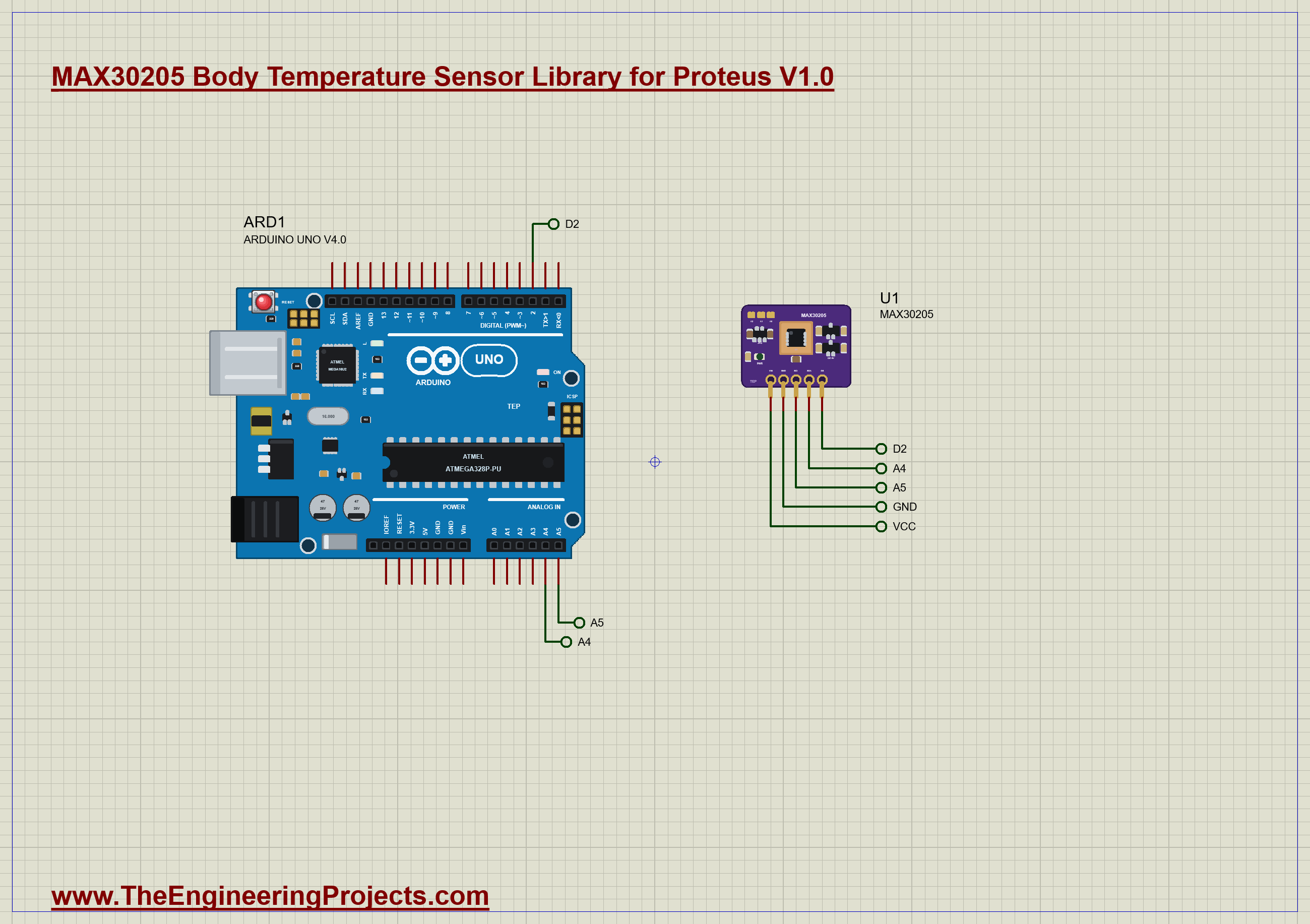
The Sketch
The sketch uses only the Wire library, with no MAX30205 library, so every byte on the bus is visible. Reading a register follows the datasheet's read sequence: the address, the pointer byte, a repeated START, the address again for reading, then two data bytes, most significant first:
int readReg16(byte reg) {
  Wire.beginTransmission(ADDR); Wire.write(reg); Wire.endTransmission(false);   // the pointer, then a repeated START
  Wire.requestFrom(ADDR, (byte)2);
  int value = Wire.read() << 8;                                                // MSB first
  value |= Wire.read();
  return value;
}
Because the register is a signed 16-bit number in 1/256 °C, turning it into degrees is a single division by 256. In setup the sketch checks that something answers at 0x48 and writes the configuration and the two limits: comparator mode, OS active low, two faults in a row, THYST at 37.5 °C and TOS at 38.0 °C. It then reads all three back to prove they arrived:
  writeReg8(REG_CONFIG, 0x08);                                                 // comparator, OS active low, 2 faults, normal format
  writeReg16(REG_THYST, fromC(37.5));
  writeReg16(REG_TOS, fromC(38.0));
Every half second it reads the temperature and prints it with its raw hex value and the state of OS. It notes when the reading passes 30 °C (the sensor is on the skin) and when it is steady: three changes in a row under 0.03 °C. It watches D2 all the time; when OS changes, it reads the temperature at once and prints it, and the UNO's LED follows the alarm.
Run the Demo
Open the project and press Run. The demo runs 46 simulated seconds, which Proteus ran in a little over four minutes on our PC. Click the board to open its pop-up; everything below is from that one run, the demo exactly as it ships.
Power-On and the Setup
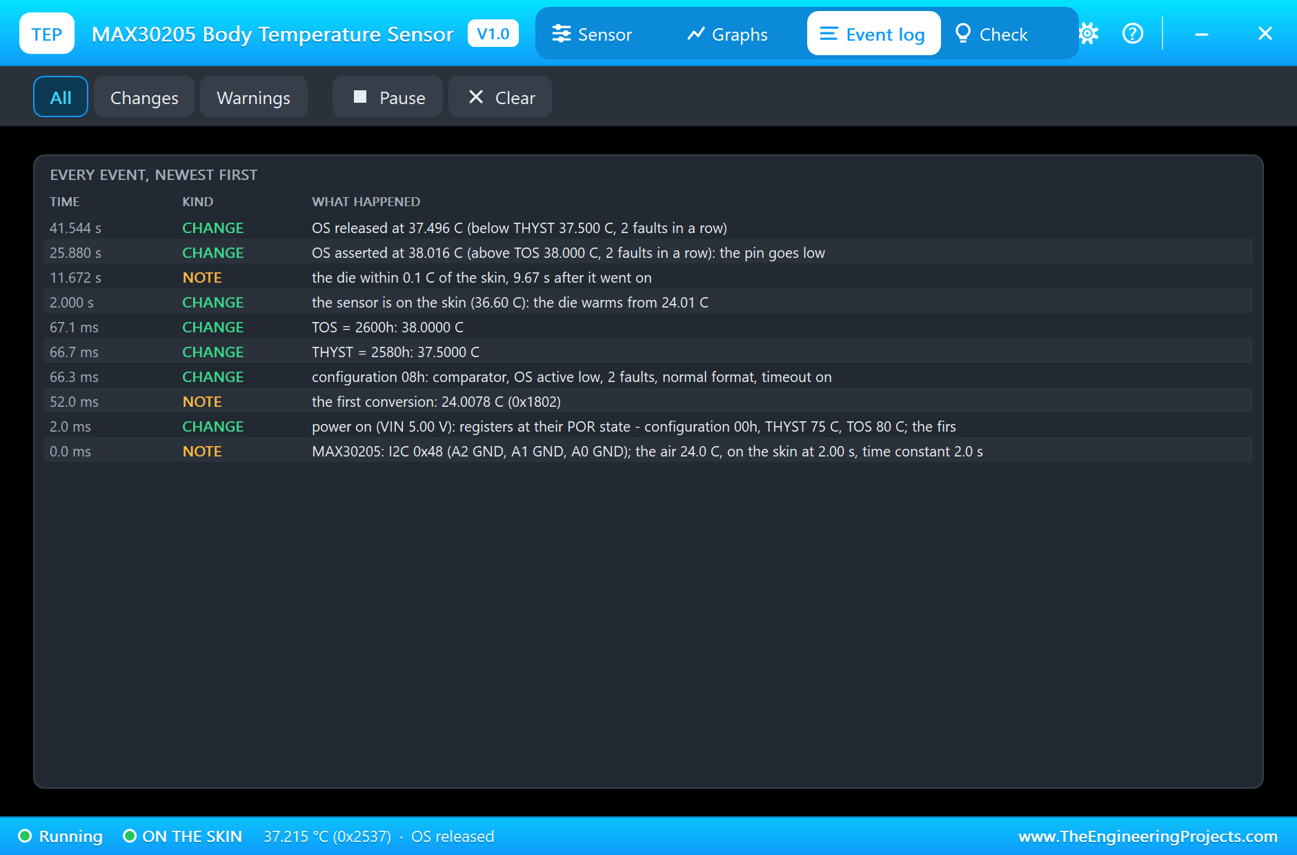
The board powers on at 2 ms with every register at its power-on state: configuration 00h, THYST 75 °C and TOS 80 °C. The first conversion is ready 50 ms later and reads 24.0078 °C (1802h), the air. A few milliseconds after that the sketch writes configuration 08h, THYST 2580h and TOS 2600h, and the event log decodes each one: comparator, OS active low, 2 faults, normal format; 37.5000 °C; 38.0000 °C. The sketch reads them back as config 0x8, THYST 37.50 C and TOS 38.00 C. In the air the readings sit at 24.00 °C, the raw value moving between 17FEh and 1800h, a step or two of the 0.009 °C repeatability.
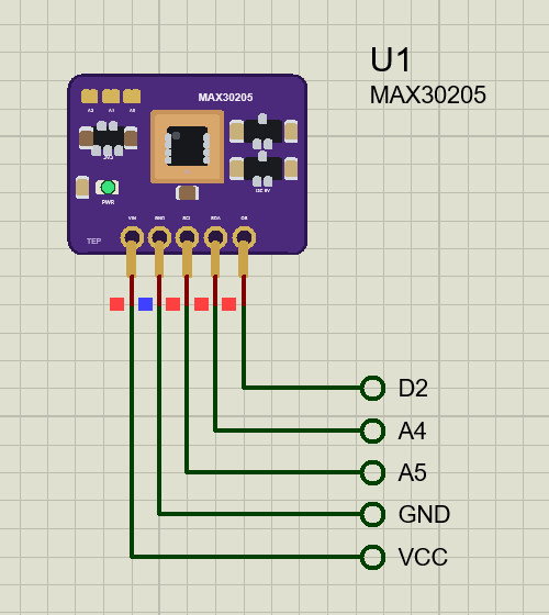
On the Skin
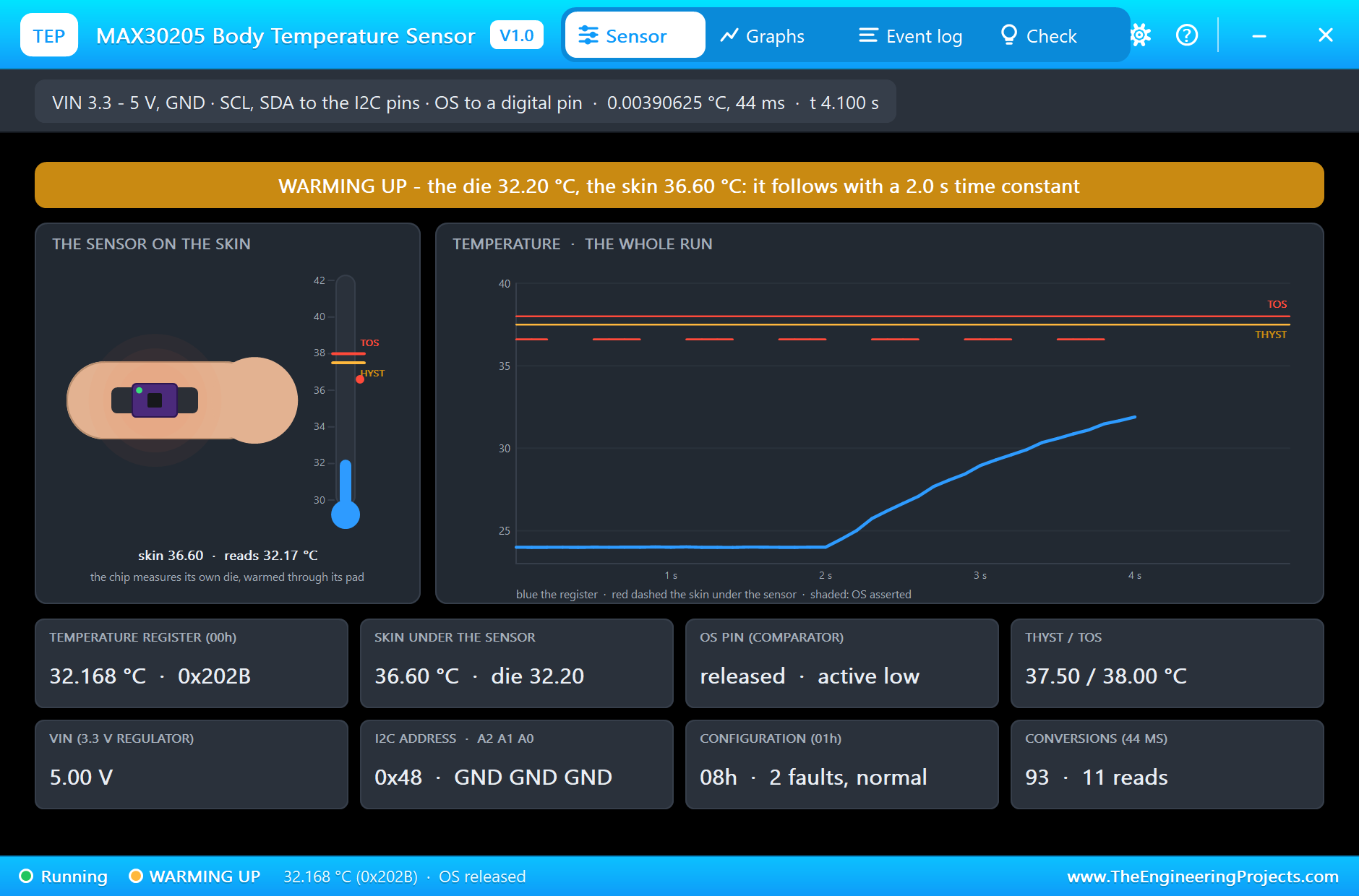
At 2 s the sensor goes on the skin. In the pop-up it drops onto the forearm, the banner turns orange for WARMING UP, and the blue line on the graph starts its climb. The die warms like a capacitor charging: fast at first, then slower and slower as it nears the skin's 36.6 °C. The sketch sees it pass 30 °C at 3.65 s, reading 31.24 °C.
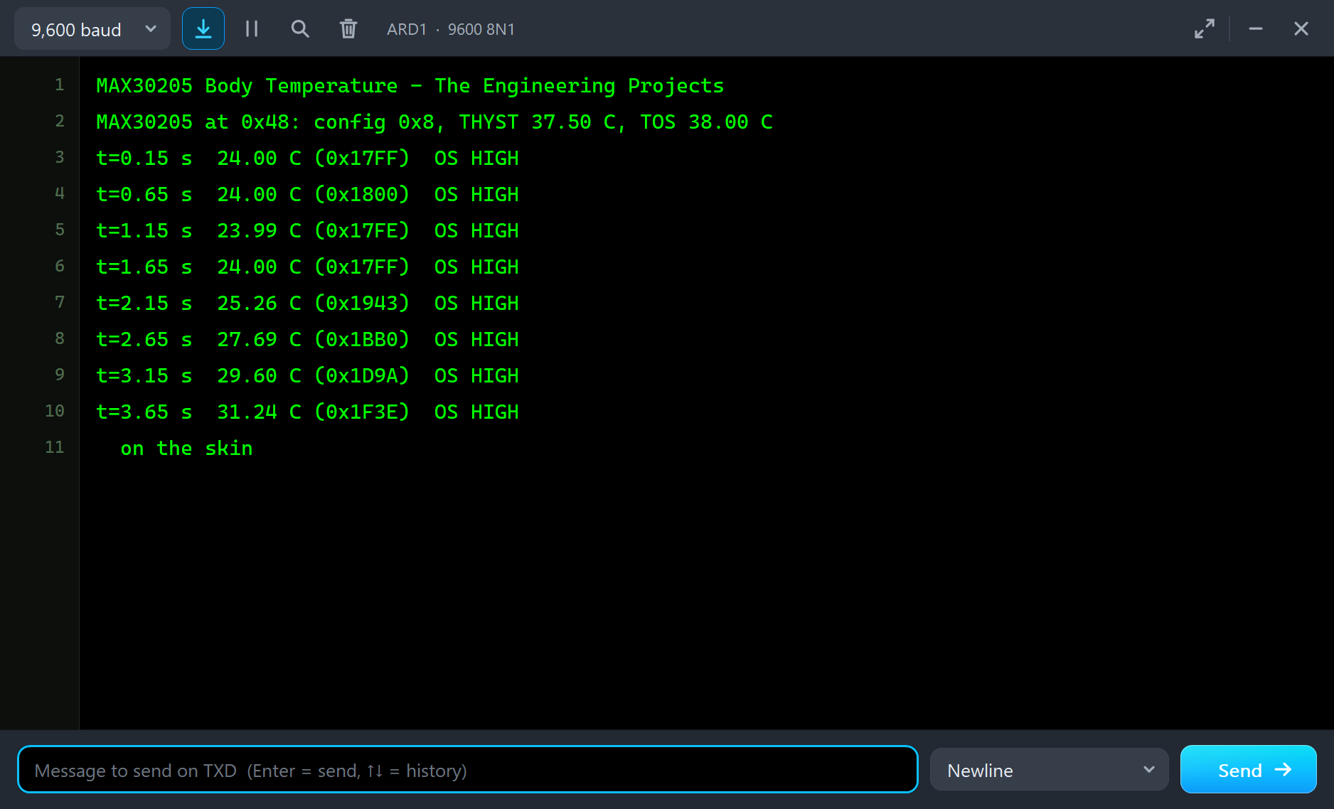
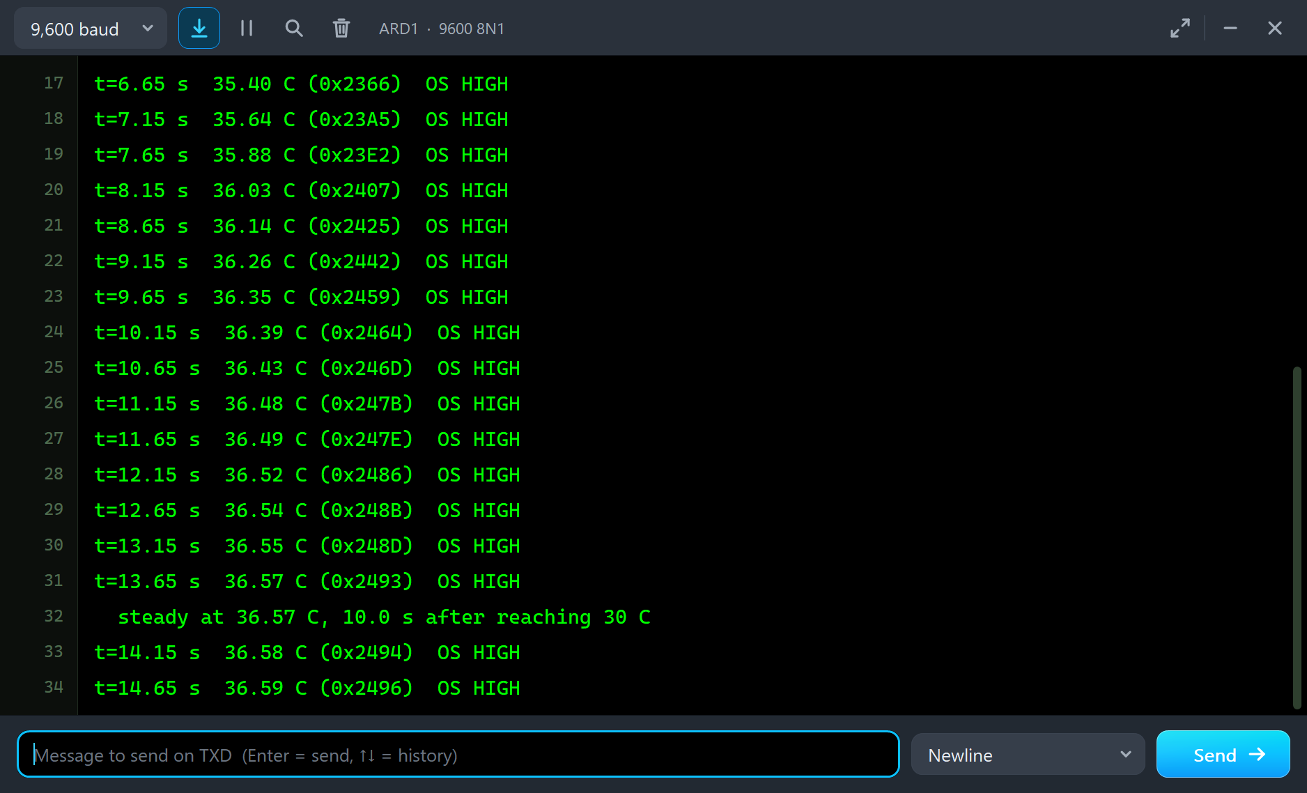
The model notes the die within 0.1 °C of the skin 9.67 s after it went on. The sketch, with its own simple test, calls the reading steady at 36.57 °C, 10.0 s after it passed 30 °C. With a 2 s time constant the die closes about 63 % of the remaining gap every 2 s, so it takes about five time constants to come within 0.1 °C of a 12.6 °C step. If the thermal path of a real patch has a time constant of a minute, the same five time constants are about five minutes. That is why clinical patches and thermometers need time on the skin before their first good reading.
The Fever and the Alarm
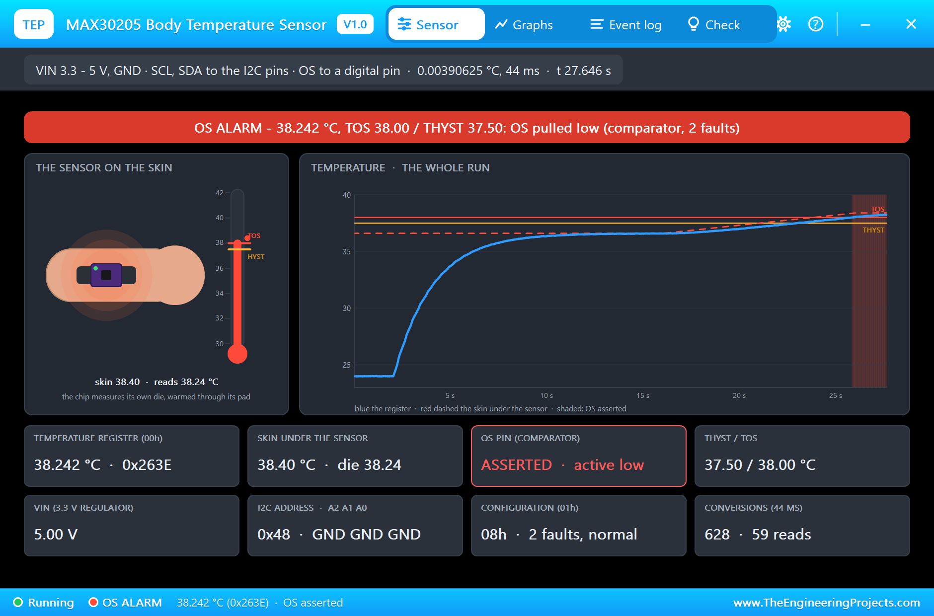
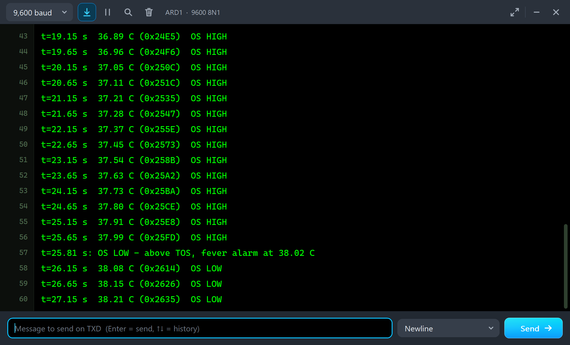
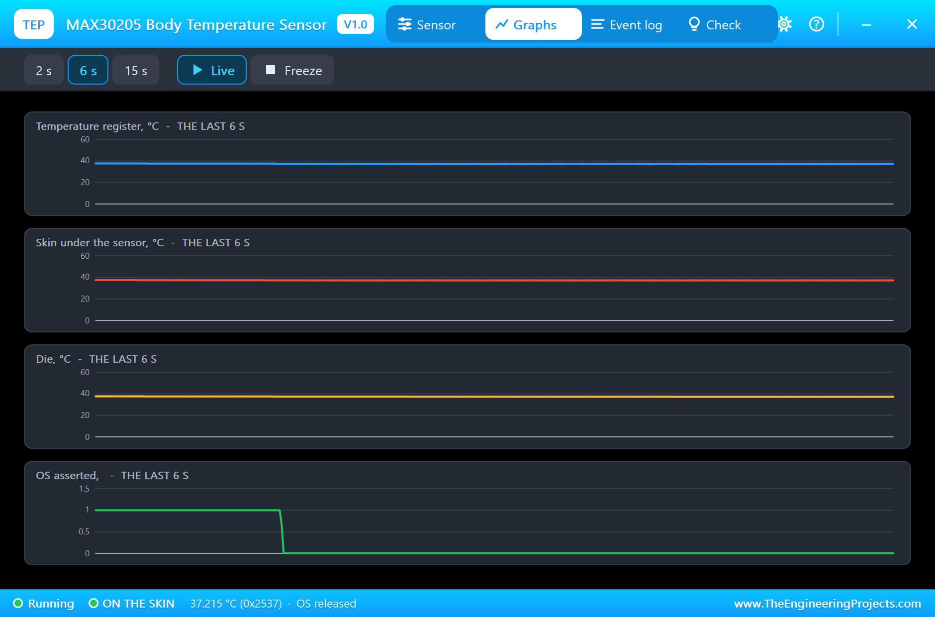
From 16 s the skin warms up at 0.18 °C per second towards 38.4 °C. The die follows, but it stays behind by about the rate times the time constant: at 25.65 s the sketch reads 37.99 °C while the skin is already near 38.3 °C. At 25.880 s a conversion reads 38.016 °C, the second in a row above TOS, and the chip pulls OS low. The pop-up's banner turns red, the OS tile reads ASSERTED and the graph starts its shaded band. The sketch sees D2 go LOW, reads 38.02 °C at once and prints the fever alarm, and the UNO's LED comes on. The highest reading of the alarm is 38.41 °C.
The Fever Breaks
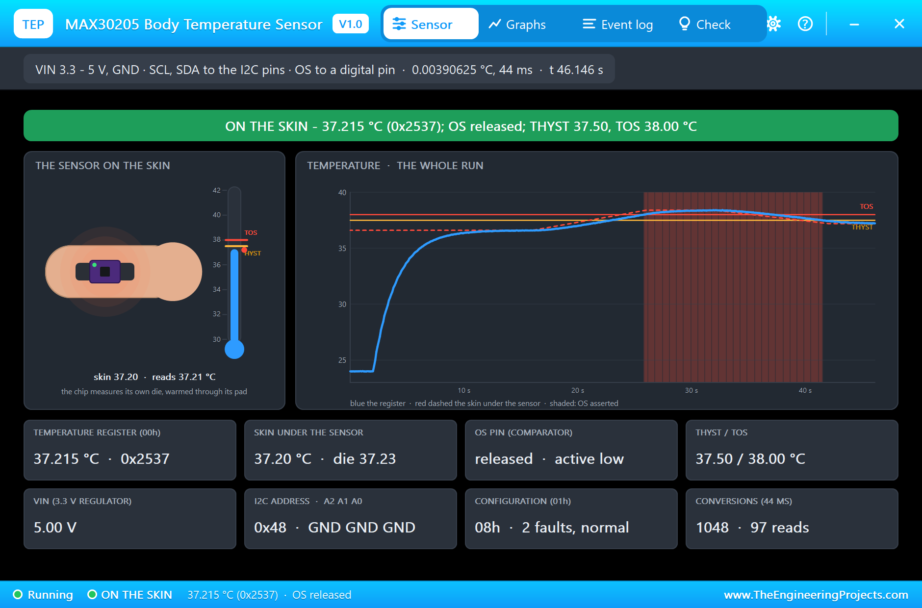
From 32 s the skin cools towards 37.2 °C. By 37.65 s the reading is back under TOS, at 37.95 °C, but OS stays low: in comparator mode it waits for THYST, not TOS. Only at 41.544 s, with a conversion at 37.496 °C, the second in a row below 37.5 °C, does the chip release OS. The sketch prints OS HIGH at 37.50 °C and the alarm's peak. That half degree of hysteresis means a temperature wandering around 38.0 °C gives one clean alarm instead of dozens. By the end of the run the reading is 37.23 °C. In 46 seconds the chip made 1048 conversions of 44 ms, and the sketch read its registers 97 times.
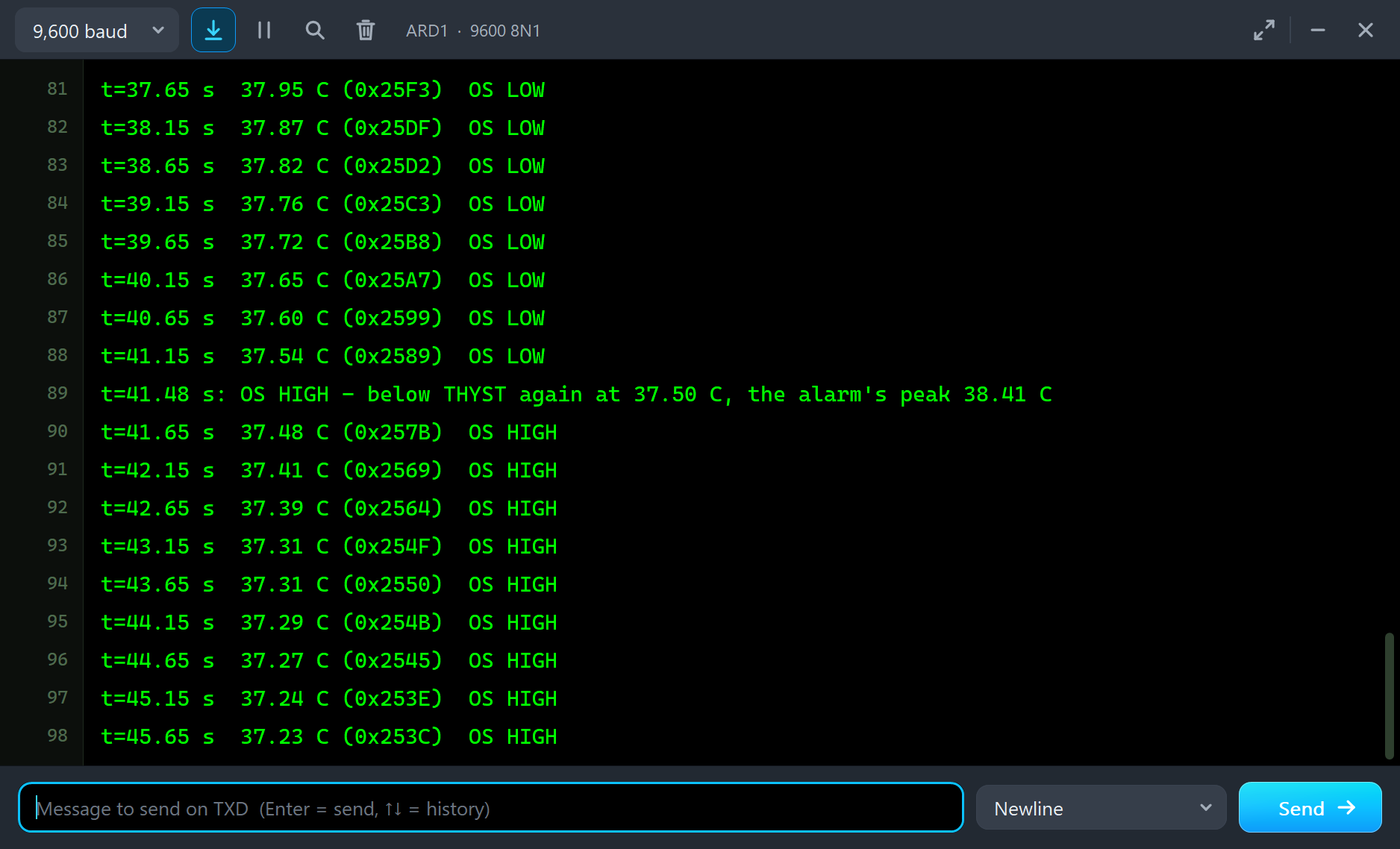
The sketch's times run a few hundredths of a second behind the model's (25.81 s against 25.880 s for the alarm), because the UNO's millis() starts counting a little after the simulation starts.
The Graphs, the Log and the Check Page
The Graphs page plots the temperature register, the skin under the sensor, the die and OS over the last 2, 6 or 15 simulated seconds; the 15 s view of the fall shows the register trailing the skin and OS dropping only below THYST. The Event log keeps the power-on, the first conversion, every configuration and limit write decoded, the moment the sensor went on, the settling and each change of OS with its temperature and fault count.
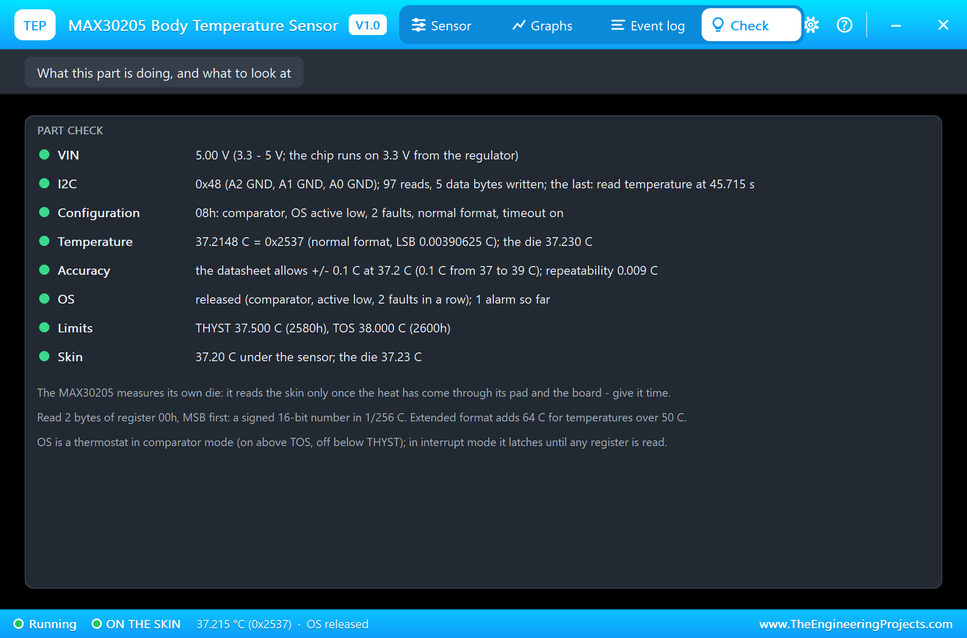
The Check page sums up the chip: VIN, the address and its jumper settings, the I2C traffic, the configuration decoded, the temperature with its raw value, the datasheet's accuracy band at that temperature, OS and the limits.
Try It Yourself
- Write configuration 0Ah instead: interrupt mode. Watch OS latch at TOS and clear on the next read; then latch again below THYST.
- Set the fault queue to 6 (configuration 18h) and see the alarm come later.
- Use shutdown and one-shot: write 01h, then 81h every 10 s, and read the result after 50 ms.
- Set the extended format (configuration 20h) and add 64 °C to every reading.
- Change ADDR to 0x49 and see the sketch fail to find it; then change the sketch.
- Set TAU to 60 s and see how long a real patch needs before the first good reading.
Ideas to Extend the Demo
- Put the sketch to sleep and wake it from the OS pin as an interrupt.
- Log the temperature every minute to an SD card for a 24-hour body temperature curve.
- Show the temperature on an OLED with a fever icon.
- Combine it with our ECG, EMG and GSR sensors for a small wearable monitor.
Your Own Sketches
The demo sketch is in the zip file, and you can change it in the Arduino IDE. New to Arduino? Start with our Arduino Tutorial for Beginners. Export the compiled binary, and set the UNO's PROGRAM property to the new file. Our guide on How to get the HEX file from Arduino shows you where the file ends up.
Things to Know Before Using a Real Sensor
- Not a medical device: for learning and hobby projects only.
- Pad to the skin: the chip measures its own die; put the thermal pad side on the skin, insulate it from the air and give it time.
- Mind the voltage: the bare chip runs from 2.7 to 3.3 V and its SDA and SCL take at most 4 V; on a 5 V board use a breakout with a regulator and level shifters.
- Skin is not core: skin temperature depends on the place and the room; armpit or forehead patches with insulation come closer to the body's core temperature.
Troubleshooting
- NO SUPPLY: VIN is missing or under 3 V.
- "no MAX30205 at 0x48": SDA and SCL swapped or not connected, or ADDR is not the address in the sketch.
- The reading is 0 °C: it was read before the first conversion, 50 ms after power-on, or the chip is in shutdown.
- The reading is 64 °C too low: the extended format is on; add 64 °C.
- OS never changes: TOS and THYST were never written (80 and 75 °C at power-on), or the pin has no pull-up.
- OS stays on in interrupt mode: it latches until any register is read.
- The part is not simulated:
TEPMAX30205.DLLis missing from MODELS and from the project folder.
Limitations of the Simulation
- The reading is the die's temperature plus the repeatability; the datasheet's accuracy bands are shown on the Check page but not added as errors.
- Self-heating, the air cooling the sensor and the patch's insulation are not modelled; one time constant stands for the whole thermal path.
- The I2C timing limits (setup and hold times) are not checked.
- Arduino is a name of Arduino; this library is not made or endorsed by Arduino, Labcenter, Maxim Integrated or Analog Devices.
- Tested in Proteus 8.5 in November 2026 (the demo as shipped). Proteus 7 is not supported.
So, that was all about the MAX30205 Body Temperature Sensor Library for Proteus. I hope it helps you build your thermometer or fever-alarm project on your own PC first: the chip's real registers and alarm, a body that warms and cools when you say, and a sketch that talks to it byte by byte. If you have any questions, ask in the comments and I will help you out. Till the next tutorial, take care and have fun!