Hello friends, I hope you all are doing great. Today, I am going to share the PSoC 6 WiFi-BT Pioneer Kit Library for Proteus, so you can run a Wi-Fi simulation of Infineon's connected PSoC board. The kit (CY8CKIT-062-WIFI-BT) carries the PSoC 62, a dual-core microcontroller with an Arm Cortex-M4 and a Cortex-M0+, and a Murata module for Wi-Fi and Bluetooth. With this library it runs your Arduino sketch in Proteus 8.5, joins a Wi-Fi network, serves web pages to a phone, and its LEDs and the SW2 button work just like on the real kit.
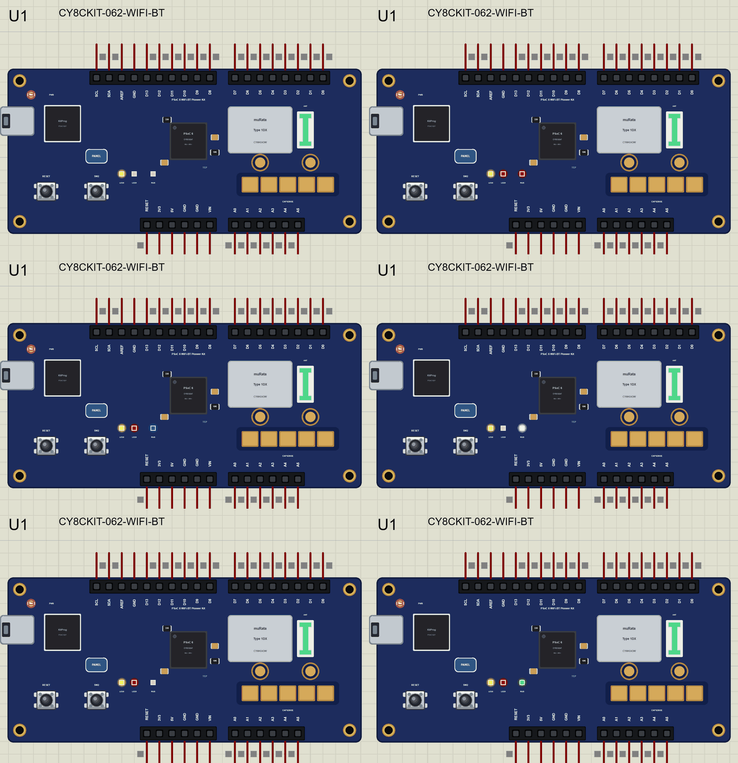
PSoC 6 WiFi-BT Pioneer Kit Library for Proteus
Latest version: V1.0 (November 2026, this tutorial)
Other new Arduino boards: UNO R4 WiFi · Nano ESP32 · UNO WiFi Rev2 · Nano 33 IoT · UNO Q · UNO R4 Minima · Nano Every · MKR WiFi 1010 · Nano RP2040 Connect · STM32 Black Pill · Nucleo-F401RE · STM32 Blue Pill · Teensy 4.1 · Arduino Due · Arduino Leonardo · Arduino Micro · BBC micro:bit V2 · GIGA R1 WiFi · MKR WAN 1310 · Nano 33 BLE Sense · XIAO nRF52840 Sense · RAK4631 WisBlock · Nano Matter · nRF52840 DK · nRF5340 DK · nRF9151 DK · nRF7002 DK · Nordic Thingy:53 · xG24 Dev Kit · xG24 Explorer Kit · Thunderboard BG22 · SiWx917 Dev Kit · B-L475E-IOT01A · NUCLEO-WB55RG · NUCLEO-WL55JC1 · NUCLEO-H743ZI2 · SAM R21 Xplained Pro · FRDM-MCXN947 · Portenta H7 · LP-CC2652R7
RF modules: nRF24L01 · nRF24L01 PA LNA · CC1101 · RFM69HCW · HC-12 · 433MHz RF · XBee
Temperature and weather sensors: DHT11 / DHT22 · DS18B20 · BME280 · BMP280 · SHT31 · AHT20 · BME680 · MLX90614 · MAX6675
Helping Tools
- Laptop WiFi Monitor: a laptop on the Wi-Fi of your design: a browser, a TCP / UDP terminal and ping
- Mobile WiFi Monitor: a smartphone that opens the pages of your board and sends it commands
- Serial Monitor Advance: a serial terminal window for the UART of your board
For the demo we built a Wi-Fi mood lamp. The kit's RGB LED is the lamp: you choose its colour on a web page from a phone, or step through the colours with SW2 on the board, and two small LEDs tell you whether the Wi-Fi is up and who chose the colour.
NOTICE: Proteus has no PSoC 6 model, so our team has put a lot of effort into building this board ourselves: the pins, the LEDs, SW2, Wi-Fi and Bluetooth LE are all our own model, and your sketch compiles with our free TEP Boards for Proteus add-on. Your feedback is the fuel that keeps us going, so please tell us what you think in the comments below. And if our free libraries help you, you can buy us a coffee. So, let's get started with the PSoC 6 WiFi-BT Pioneer Kit Library for Proteus:
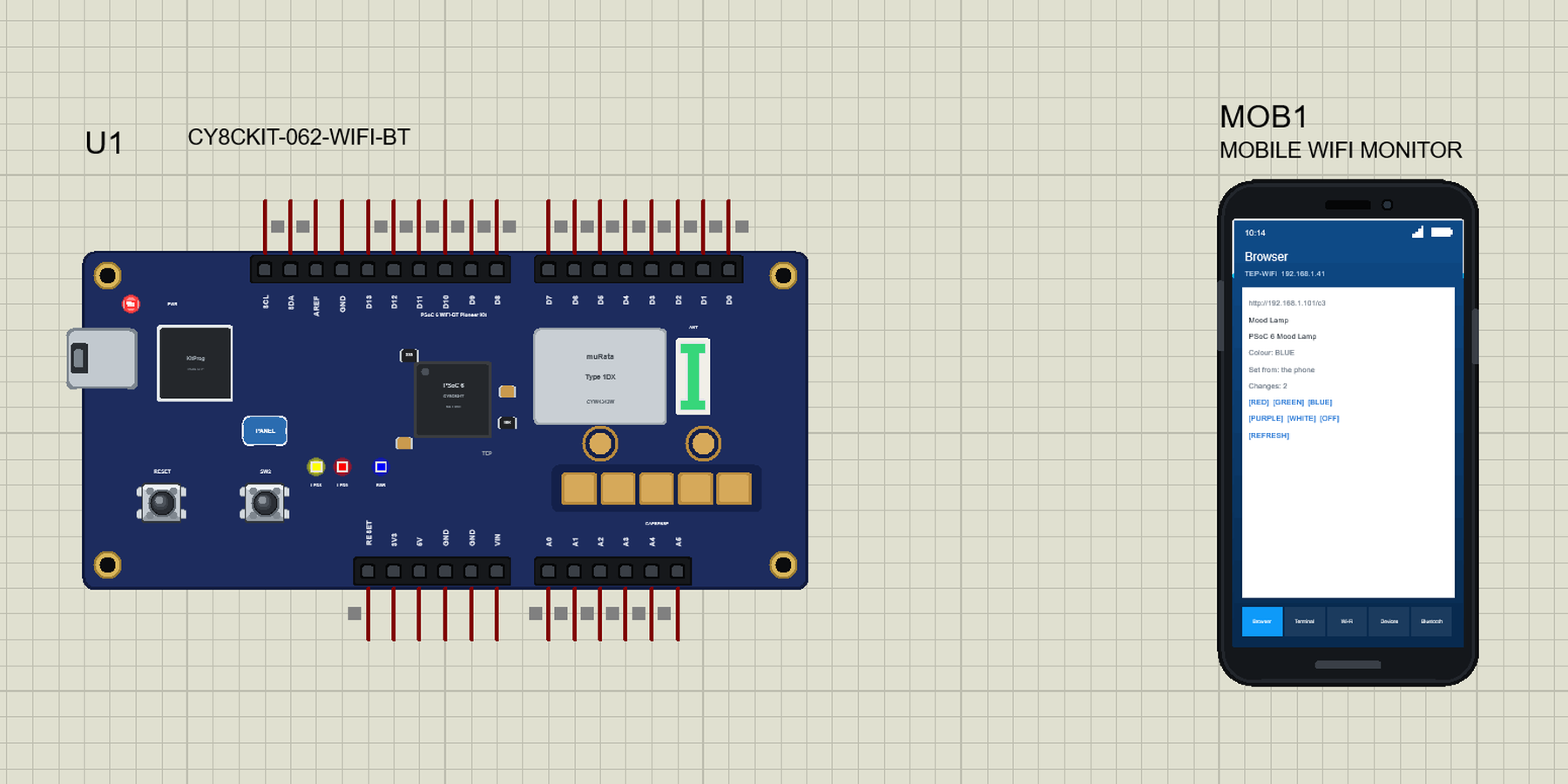
What is the PSoC 6 WiFi-BT Pioneer Kit?
The PSoC 6 WiFi-BT Pioneer Kit is Infineon's evaluation board for connected PSoC 6 designs. PSoC stands for Programmable System-on-Chip: the family was created by Cypress Semiconductor, which became part of Infineon in 2020. The kit's PSoC 62 (CY8C6247) has two Arm cores - a Cortex-M4 at 150 MHz for the application and a Cortex-M0+ at 100 MHz for housekeeping and security - with 1 MB of flash and 288 KB of SRAM. Next to it sits the Murata Type 1DX module with Infineon's CYW4343W radio, which gives the board Wi-Fi and Bluetooth. A second chip, a PSoC 5LP, works as the KitProg programmer and debugger, so one USB cable programs, debugs and powers the kit.
| Part | The real Pioneer Kit | In the library |
|---|---|---|
| MCU | PSoC 62: Cortex-M4 150 MHz + Cortex-M0+ 100 MHz | your Arduino sketch |
| Radio | Murata Type 1DX (CYW4343W): Wi-Fi + Bluetooth | WiFi.h and ArduinoBLE |
| LEDs | LED8, LED9 and an RGB LED, all active LOW | LED8, LED9, LED_RED, LED_GREEN, LED_BLUE |
| Button | SW2 (user), SW1 (reset) | SW2 and RESET |
| Touch | CAPSENSE slider and two CAPSENSE buttons | drawn |
| Headers | Arduino Uno R3 compatible | D0 to D15, A0 to A5 |
| USB | KitProg (PSoC 5LP): program, debug, serial | the serial monitor |
| Memory | 1 MB flash, 288 KB SRAM | about 256 KB of flash, 8 KB of RAM |
What Makes PSoC Different?
Most microcontrollers have a fixed set of peripherals: so many UARTs, so many timers, pins wired to fixed functions. A PSoC adds blocks you can configure yourself - smart I/O that does simple logic right at the pins, programmable analog parts, and a very flexible routing of signals to pins. A designer can build a peripheral the chip does not have, or move a function to a different pin, without a new board. The PSoC 6 family is also built for low power, so the same chip that serves a web page can sleep at a few microamps between jobs.
Two Cores With Two Jobs
On the PSoC 62 the Cortex-M4 runs the application and the Cortex-M0+ usually looks after the system: low-power modes, secure boot and, in many designs, the communication with the radio. The two cores share the memory and pass messages through an inter-processor channel. Our simulation runs your sketch as one program, which is how most projects start; the split between the cores comes later, when power and security matter.
The Murata Type 1DX Module
The Type 1DX is a small shielded module with the CYW4343W inside: a 2.4 GHz Wi-Fi radio and a Bluetooth radio on one chip, with a chip antenna on the kit next to it. The same module sits on Arduino's Portenta H7, so if you have seen our Arduino Portenta H7 Library for Proteus, the silver can on this board will look familiar. Wi-Fi gives the kit a link to a router and the internet, while Bluetooth LE talks to phones and sensors nearby at very low power.
KitProg: a Programmer on the Board
The left end of the kit is a complete programmer: a PSoC 5LP with its own USB connector. It flashes and debugs the PSoC 6 through SWD, and it also gives the computer a virtual serial port, so the sketch's Serial output arrives on the PC through the same cable. In our simulation that USB connector opens the serial monitor, which is the same window as our TEP Serial Monitor Advance for Proteus.
CAPSENSE Touch
Infineon's CAPSENSE turns copper on the board into touch buttons and sliders. The Pioneer Kit has a five-segment slider and two buttons, measured by the PSoC 6 itself - no extra touch chip. They are drawn on our board so it looks like the real one; touch sensing is not part of this first version of the simulation.
Where Is It Used?
The Pioneer Kit is a starting point for smart home devices, wearables, industrial sensors and secure cloud-connected products. Infineon offers it with its ModusToolbox software, examples for the major cloud platforms and a TFT display shield in the box. Universities use it to teach embedded systems with a modern dual-core chip and real wireless links. For a Bluetooth LE board of another maker in this series, see our LP-CC2652R7 Library for Proteus.
A simulation lets you build the logic and the web interface before the kit is on the desk: the LEDs, the button and the page. When the sketch works in the Proteus simulation, the real board only has to confirm it.
Features of the PSoC 6 WiFi-BT Pioneer Kit Library for Proteus
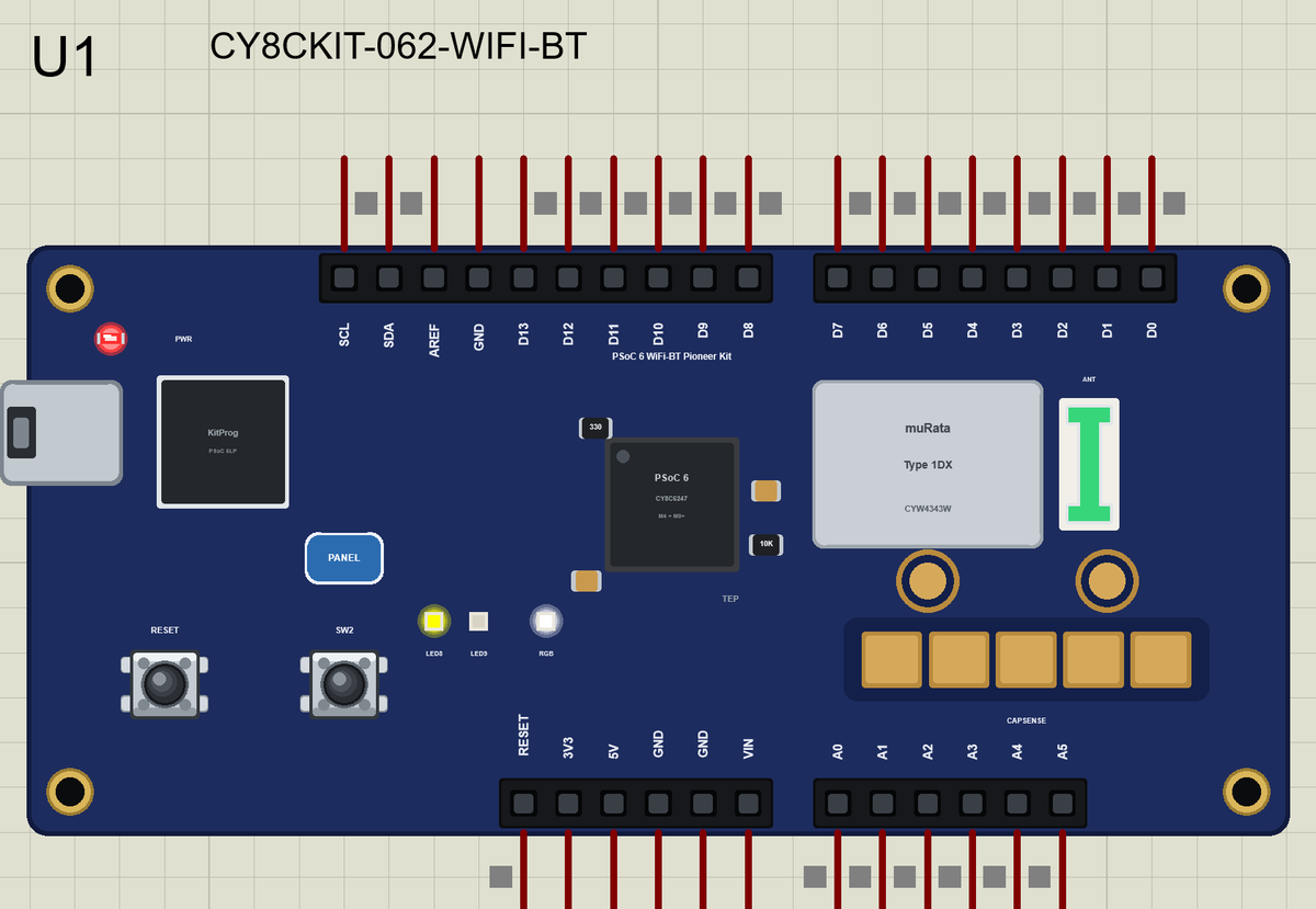
- The board as it looks: the navy Pioneer Kit with the KitProg and its USB, the PSoC 62, the Murata Type 1DX can and its chip antenna (it glows with the Wi-Fi), LED8, LED9, the RGB LED, SW2, RESET, the CAPSENSE slider and buttons, our PANEL pad and the Arduino headers, drawn compact, with our small TEP signature.
- Your sketch: a .hex for "Infineon PSoC 6 WiFi-BT Pioneer Kit (TEP Proteus)" with Arduino-style names: D0 to D15, A0 to A5, LED8, LED9, LED_RED, LED_GREEN, LED_BLUE and SW2.
- Wi-Fi: WiFi.h - WiFi.begin() waits for the join, WiFiServer, WiFiClient, WiFiUDP - with our router, our phone and our laptop.
- Bluetooth LE: ArduinoBLE, with the phone as the central.
- Real LEDs and a real button: every LED lights when its pin is LOW, the RGB colours mix, and SW2 reads LOW while you click it, as on the real kit.
- A complete package: about 3.4 MB with the part, the add-on, the phone and the demo, without the source code of the models.
The PSoC 6 WiFi-BT Pioneer Kit in Proteus Simulation
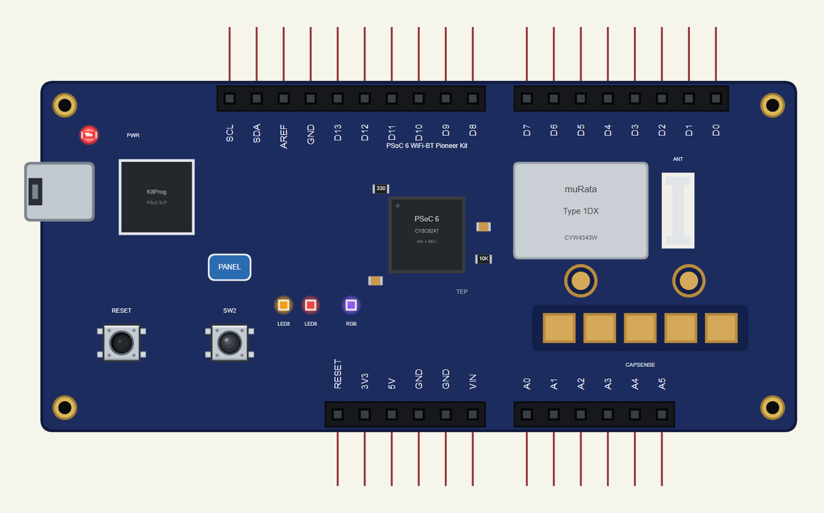
Search PSOC in Pick Devices; the device CY8CKIT-062-WIFI-BT is in TEPPSOC6.LIB (Microprocessor ICs, Wi-Fi Boards), with the prefix U. The KitProg's USB opens the serial monitor, and the PANEL pad or a click on the Murata module opens the Wi-Fi panel.
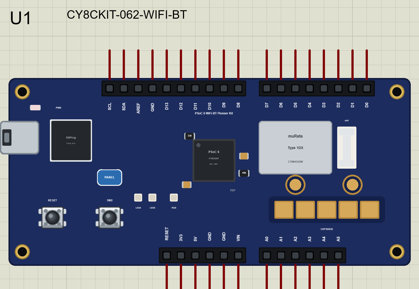
The Pins
| Pins | What the library does with them |
|---|---|
| D0 to D13 | GPIO, PWM, attachInterrupt; Serial1 on D0 / D1; SPI on D10 to D13 |
| SDA, SCL (D14, D15) | Wire, or GPIO |
| A0 to A5 | analogRead 0 to 1023 for 0 to 3.3 V, or GPIO |
| LED8, LED9 | the two user LEDs, lit when LOW (LED_BUILTIN is LED8) |
| LED_RED, LED_GREEN, LED_BLUE | the RGB LED, each colour lit when LOW |
| SW2 | the user button, LOW while pressed |
| 3V3, 5V, GND, RESET | the supply and the reset |
The LEDs and SW2
The real kit wires its LEDs from 3.3 V through a resistor to the PSoC pin, so a LOW on the pin lights the LED. The library does the same, which means a sketch written for the simulation drives the real LEDs the right way round. SW2 connects its pin to ground, so with INPUT_PULLUP the pin reads HIGH at rest and LOW while you press it. In Proteus you simply click SW2 on the board.
Download PSoC 6 WiFi-BT Pioneer Kit Library for Proteus
Click the button below to download PSoC-6-WiFi-BT-Pioneer-Kit-Library-for-Proteus-v1.0.zip (about 3.4 MB, without the source code of the models):
PSoC 6 WiFi-BT Pioneer Kit Library for Proteus V1.0- README.txt: installation, the demo, the pins, the properties, troubleshooting and the limits.
- Proteus Library Files:
TEPPSOC6.LIBand the phone and laptop (TEPMOBILE.LIB,TEPLAPTOP.LIB). - Proteus Model Files:
TEPNET.DLL, the model of the board, the phone and the laptop. - Arduino Code: the demo sketch and the TEP Boards for Proteus add-on 1.77.0, with WiFi and ArduinoBLE.
- Proteus Simulation: the demo project, its HEX file and a copy of the DLL.
No Proteus yet? Read How to Download and Install Proteus 7 and 8. New to libraries? Follow How to Install a New Library in Proteus.
How to Install PSoC 6 WiFi-BT Pioneer Kit Library for Proteus
- Close Proteus and extract the whole zip file, for example to your Desktop.
- Copy the files from Proteus Library Files into the LIBRARY folder of Proteus.
- Copy the DLLs from Proteus Model Files into the MODELS folder, replacing an older
TEPNET.DLL. - Delete
TEPPSOC6.IDXfrom the LIBRARY folder if it is there. - For your own sketches, copy Arduino Code\TEP Boards for Proteus\hardware into your Arduino sketchbook (Documents\Arduino) and restart the Arduino IDE; the board is Infineon PSoC 6 WiFi-BT Pioneer Kit (TEP Proteus).
- Start Proteus, press P and search for PSOC.
Demo: a Wi-Fi Mood Lamp in Simulation
A mood lamp is a small project with all the parts of a real connected product: an output people see, a local control on the device, a remote control on a phone, and a status display that tells you what state the device is in. It is also a perfect first sketch for a new board, because every LED of the kit has a job.
Open PSoC6-WiFi-Mood-Lamp.pdsprj. U1 runs PSoC6_Mood_Lamp.hex, and MOB1 is our Mobile WiFi Monitor, a phone on the same Wi-Fi; its browser's home page is the board's page. No other parts are needed: the lamp, the status lights and the button are all on the kit.
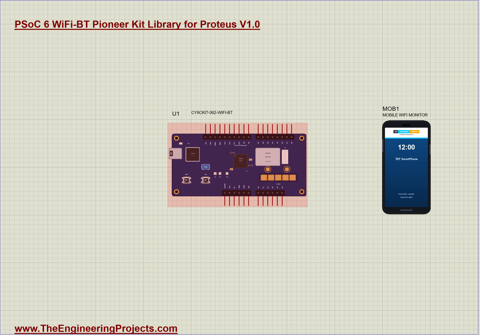
| On the board | What it shows |
|---|---|
| RGB LED | the lamp: RED, GREEN, BLUE, PURPLE, WHITE or OFF |
| LED8 | on while the Wi-Fi is connected |
| LED9 | on while the colour was chosen from the phone, off when SW2 chose it |
| SW2 | the next colour, on the board itself |
The Colours
Each colour is a name and three on/off values for red, green and blue. Purple is red plus blue, white is all three:
struct Colour { const char *name; bool r, g, b; };
const Colour COLOURS[] = {{"OFF", 0, 0, 0}, {"RED", 1, 0, 0}, {"GREEN", 0, 1, 0}, {"BLUE", 0, 0, 1},
                          {"PURPLE", 1, 0, 1}, {"WHITE", 1, 1, 1}};
Changing the Colour
setColour() is the only place where the colour changes, whether the phone or SW2 asked for it. It remembers who asked, counts the changes and prints one line:
void setColour(byte c, bool phone) {
  if (c == colour && phone == fromPhone) return;
  colour = c;
  fromPhone = phone;
  changes++;
  showColour();
  Serial.print(F(">> Lamp ")); Serial.print(COLOURS[c].name); Serial.println(phone ? F(" (from the phone)") : F(" (SW2)"));
}
showColour() then writes the pins. Every LED of the kit lights when its pin is LOW, so the sketch writes LOW for "on":
void showColour() {
  digitalWrite(LED_RED, COLOURS[colour].r ? LOW : HIGH);
  digitalWrite(LED_GREEN, COLOURS[colour].g ? LOW : HIGH);
  digitalWrite(LED_BLUE, COLOURS[colour].b ? LOW : HIGH);
  digitalWrite(LED9, fromPhone ? LOW : HIGH);
}
The Button on the Board
readButton() watches SW2 for a change from HIGH to LOW - the moment of the press - and steps to the next colour:
void readButton() {
  const bool now = digitalRead(SW2);
  if (now == lastSw2) return;
  lastSw2 = now;
  if (now == LOW) setColour((colour + 1) % N_COLOURS, false);   // the next colour
}
The Web Page
handleWeb() reads the first line of each request; an address like /c3 chooses a colour by its number, and every request gets the page back:
void handleWeb() {
  WiFiClient client = server.available();
  if (!client) return;
  String request;                                           // the first line: "GET /c3 HTTP/1.1"
  const unsigned long t0 = millis();
  while (client.connected() && millis() - t0 < 1000) {
    if (!client.available()) continue;
    const String line = client.readStringUntil('\n');
    if (!request.length()) request = line;
    if (line.length() <= 1) break;                          // the empty line after the header
  }
  if (request.startsWith("GET /c")) {
    const int c = request.substring(6).toInt();
    if (c >= 0 && c < N_COLOURS) setColour(c, true);
  }
  sendPage(client);
  delay(1);
  client.stop();
}
Joining the Wi-Fi
WiFi.begin() waits until the board has joined and returns the status, so the sketch simply tries again until it is connected, and then lights LED8:
  while (WiFi.begin(SSID, PASS) != WL_CONNECTED) { Serial.println(F("  retrying...")); delay(2000); }
  digitalWrite(LED8, LOW);                                  // LED8: the Wi-Fi link
  server.begin();
Run the Simulation
Press Run. The board joins TEP-WiFi, prints its address and the page's link, and LED8 lights:
PSoC 6 WiFi-BT Wi-Fi Mood Lamp - The Engineering Projects
Connecting to TEP-WiFi
Wi-Fi connected, IP 192.168.1.101
Lamp page: http://192.168.1.101/
SW2 = the next colour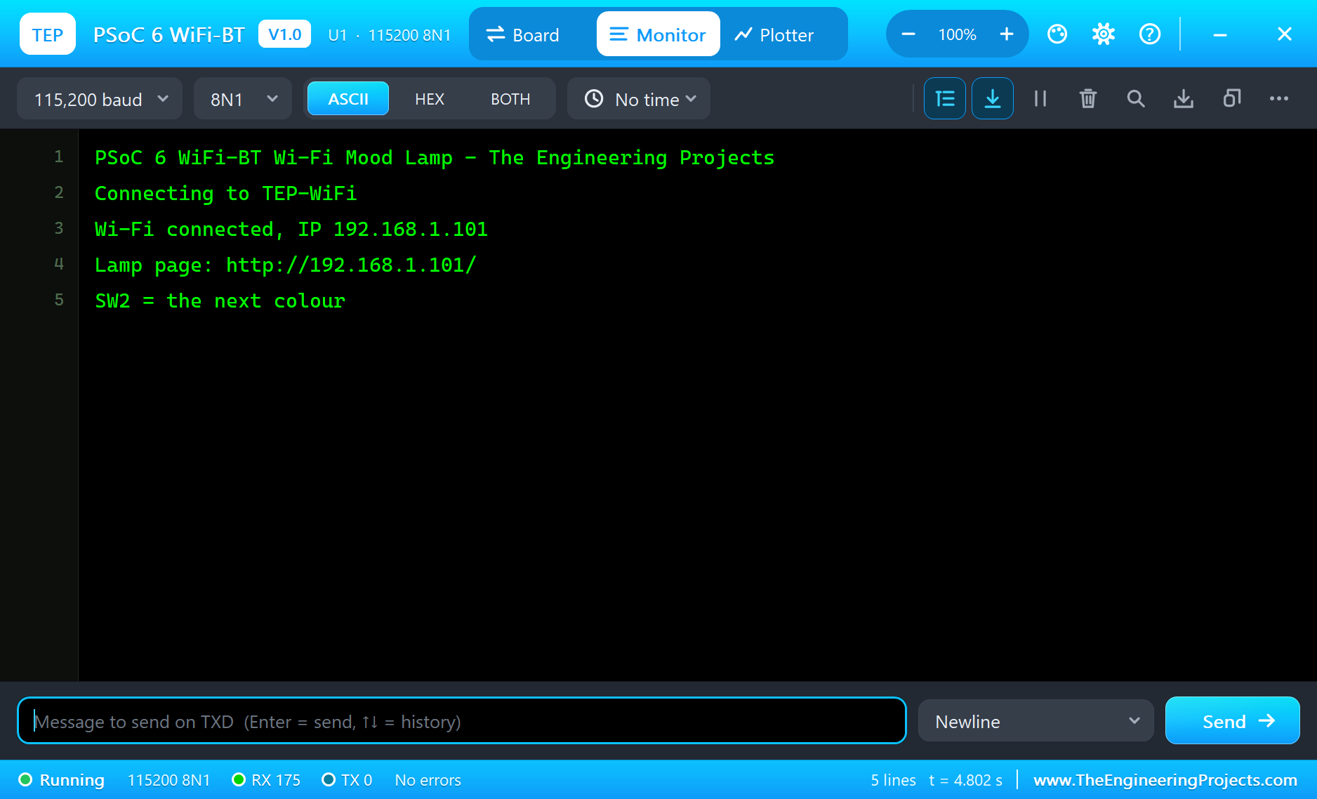
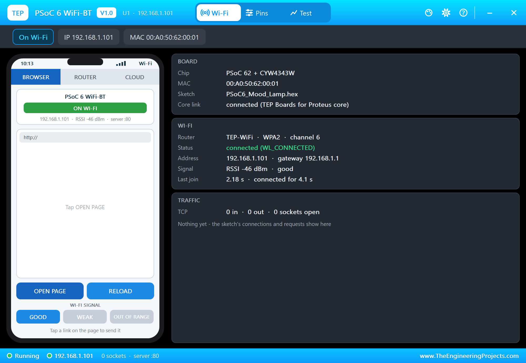
Open the Page
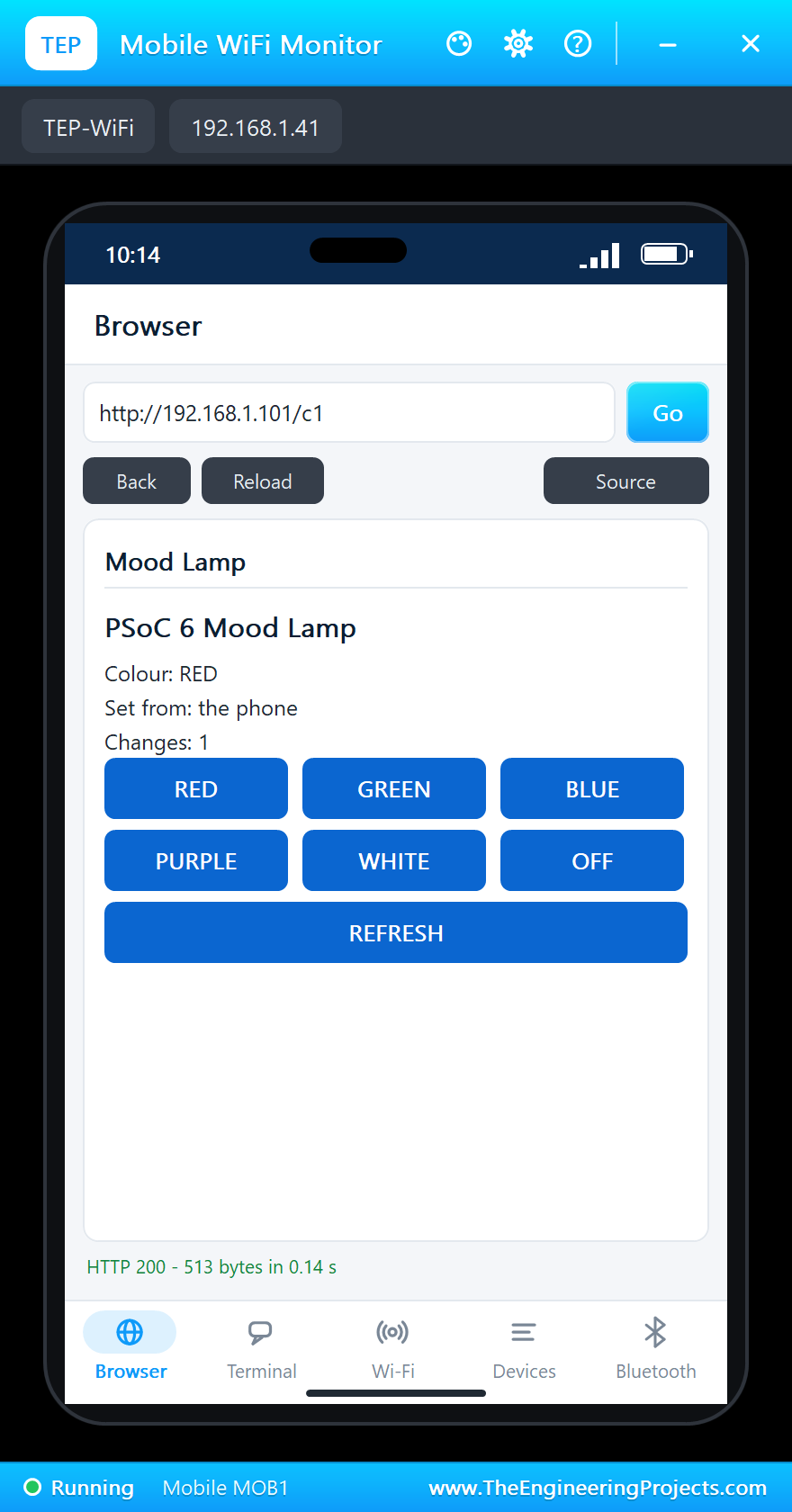
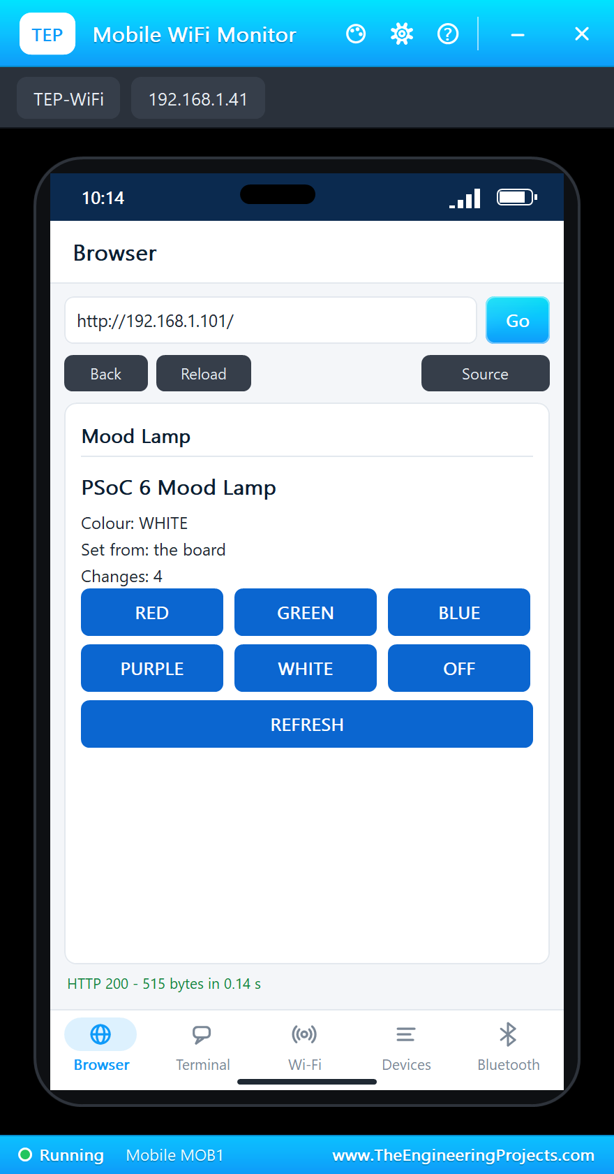
Click the phone and press Go: the browser opens the board's page, with the colour, who set it, the number of changes and the colour links.
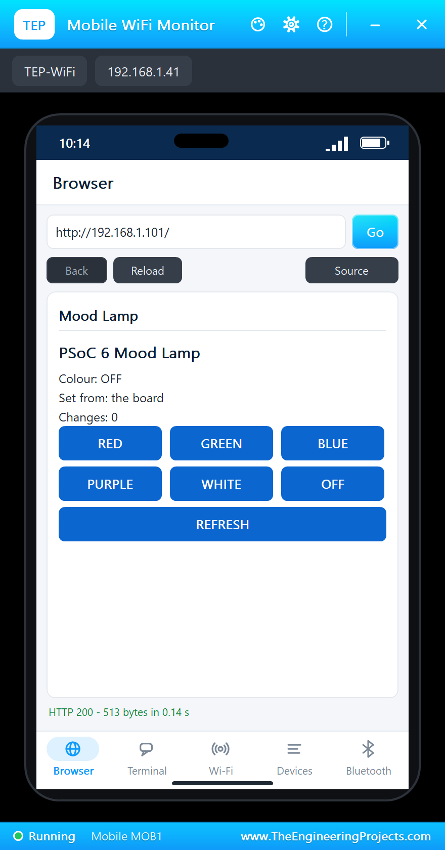
Pick a Colour
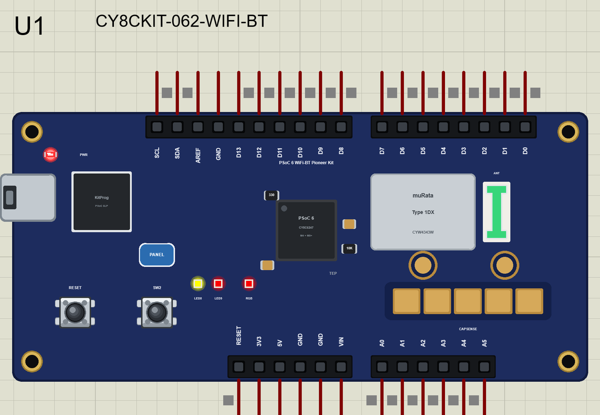
Tap RED. The RGB LED turns red, LED9 lights because the phone chose the colour, and the page shows the change:
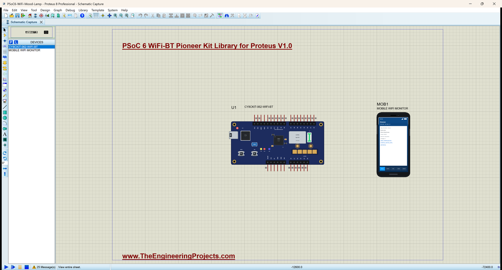
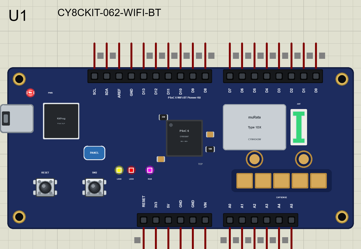
Tap BLUE, then PURPLE: purple is the red and the blue LED together. Here is the complete circuit while the simulation runs:
SW2 on the Board
Now click SW2 on the kit. The lamp steps to the next colour, WHITE, and LED9 goes off, because this time the board chose the colour. Tap REFRESH on the phone and the page shows it too:
Off and On Again
Finally tap OFF and then GREEN. The monitor shows every change and where it came from:
>> Lamp RED (from the phone)
>> Lamp BLUE (from the phone)
>> Lamp PURPLE (from the phone)
>> Lamp WHITE (SW2)
>> Lamp OFF (from the phone)
>> Lamp GREEN (from the phone)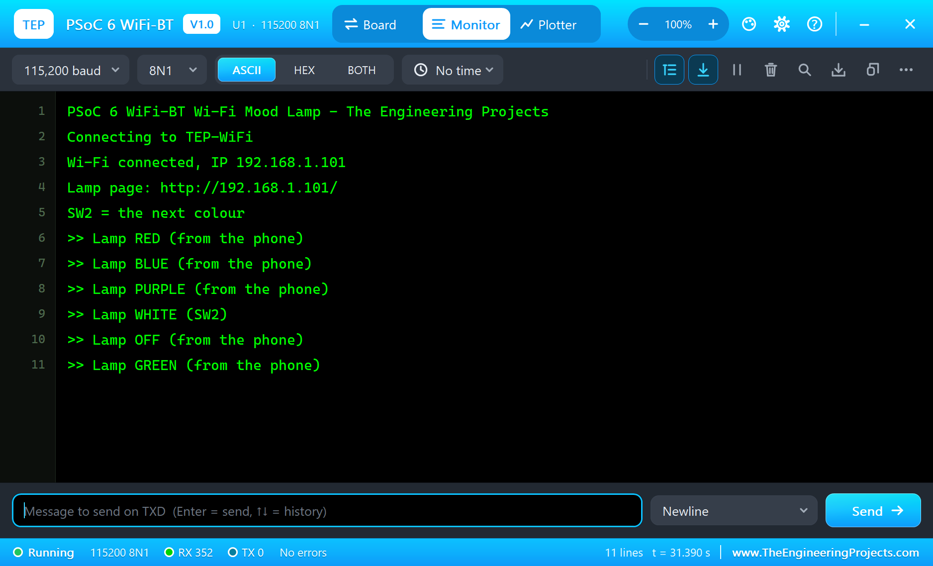
How the Colours Mix
An RGB LED is three LEDs in one package. Light adds up: red and green give yellow, red and blue give purple (often called magenta), green and blue give cyan, and all three give white. With only on and off for each colour you get eight states, including off. With analogWrite() on the three pins you can dim each colour and mix thousands of shades - one of the first things to try once the demo works.
Why a Status LED for "Who Chose It"?
When a device can be controlled from two places, people get confused if it changes by itself. LED9 answers the question at a glance: on means someone changed the lamp from a phone, off means someone pressed the button on the board. The serial monitor and the page say the same in words. Real products use the same idea - a small icon or LED that shows the device is under remote control.
One Place for Every Change
The phone and SW2 both call setColour(), and only setColour() writes the LEDs and prints. That keeps the board, the page and the log in step whatever happens: there is no way to change the lamp without LED9, the counter and the monitor knowing about it. It is a good habit for every connected sketch.
A Page Without a Web Library
The sketch answers HTTP itself: it writes the status line, the content type, an empty line and the HTML, with every fixed piece of text in flash through F(). The colour links are plain addresses, so the page works from any browser on the network, not only from our phone, and the whole page is built in a loop over the colour table - add a colour to the table and it appears on the page by itself.
Bluetooth LE on the Same Board
The demo uses Wi-Fi, but the same board also speaks Bluetooth LE through ArduinoBLE. A lamp could offer its colour as a characteristic, so a phone next to it changes the colour without any network, while the web page serves everyone on the Wi-Fi. Our Mobile WiFi Monitor has a Bluetooth app for exactly that, as in our other Bluetooth demos.
Try It Yourself
- Add CYAN and YELLOW to the colour table - the page shows them without any other change.
- Dim the lamp with
analogWrite()and add BRIGHTER and DIMMER links. - Make SW2 turn the lamp off when you hold it for two seconds.
- Offer the colour over Bluetooth LE with ArduinoBLE as well, for the phone's Bluetooth app.
Ideas to Extend the Lamp
- Get the time from NTP and fade the lamp to a warm colour in the evening.
- Add a light sensor on A0 and switch the lamp on when the room gets dark.
- Let several lamps on the network follow one master lamp over UDP.
- Show the colour as a coloured box on the page, not only as a word.
Your Own Sketches
Write the sketch in the Arduino IDE with the board Infineon PSoC 6 WiFi-BT Pioneer Kit (TEP Proteus), use Sketch > Export Compiled Binary and set the part's PROGRAM property to the .hex. Use the router name and password of the part's WIFISSID and WIFIPASS.
Moving to a Real Pioneer Kit
- Install ModusToolbox from Infineon and create a project for the CY8CKIT-062-WIFI-BT.
- Start from Infineon's Wi-Fi examples: the Wi-Fi Connection Manager joins the network and an HTTP server example serves pages.
- Move the logic of the demo across: the colour table,
setColour(), the button and the page. - Use the same LEDs and button: LED8 is P1_5, LED9 P13_7, the RGB LED P0_3, P1_1 and P11_1, SW2 P0_4.
- Program the kit through the KitProg's USB and open its serial port at 115200 baud.
The ideas, the pins and the behaviour stay the same; only the API names change between the Arduino sketch and ModusToolbox.
Things to Know Before Using a Real Pioneer Kit
- 3.3 V logic: the pins are 3.3 V; check every Arduino shield before you plug it in.
- The tools: the real kit is programmed with Infineon's ModusToolbox, so plan the move of your logic, not of the sketch file itself.
- The KitProg: it is the kit's programmer and serial port in one; keep its USB connected while you test.
- The TFT shield: it plugs onto the Arduino headers and uses some of the pins, so check them before you add your own parts.
Properties of the PSoC 6 WiFi-BT Pioneer Kit
| Property | What it does |
|---|---|
| PROGRAM | the sketch: a .hex from TEP Boards for Proteus (board "Infineon PSoC 6 WiFi-BT Pioneer Kit") |
| WIFISSID, WIFIPASS | the router the board sees and its password |
| MONITOR, BAUD, AUTOOPEN | the built-in serial monitor: on, its baud rate (115200), open at Run |
| TIME | the clock for NTP: PC, or a fixed UTC time |
Troubleshooting
- "retrying...": the network name or the password in the sketch differs from WIFISSID and WIFIPASS.
- The phone shows nothing: press Go after the page's address is printed; the sketch must call
server.begin(). - The LED looks inverted: LED8, LED9 and the RGB LED light when their pin is LOW.
- SW2 does nothing: use
pinMode(SW2, INPUT_PULLUP)and read LOW as pressed. - A number goes wrong above 32767: int is 16 bits in the simulation - use long.
Limitations of the Simulation
- Your sketch is one program: the Cortex-M0+ core and ModusToolbox are not modelled.
- CAPSENSE, the KitProg's own buttons, the microSD socket, the QSPI flash and the TFT shield are drawn or not modelled.
- Your sketch gets 8 KB of RAM in the simulation, and int is 16 bits there.
- PSoC, CAPSENSE and ModusToolbox are names of Infineon Technologies, Murata of Murata and Arduino of Arduino, and the Bluetooth word mark belongs to Bluetooth SIG; this library is not made or endorsed by them or by Labcenter.
- Tested in Proteus 8.5 in November 2026 (the demo as shipped, about 30 s of simulation). Proteus 7 is not supported.
So, that was all about the PSoC 6 WiFi-BT Pioneer Kit Library for Proteus. I hope it helps you try your connected ideas on a PSoC 6 in a simulation before you buy the kit - the LEDs, the button, the web page and the phone, all on one sheet. If you have any questions, ask in the comments and I will help you out. Till the next tutorial, take care and have fun!