Hello friends! Today we will send an SMS using a PIC18F452 microcontroller and a SIM900 modem. We will use mikroC PRO for PIC and the hardware UART, beginning with the electrical connection and then following the command exchange that submits a text message. The command sequence is related to our earlier Arduino SMS sending project . The microcontroller code changes, but the modem still needs a valid supply, compatible serial signals, network registration and correctly terminated AT commands. We will improve the original example by waiting for responses instead of assuming that fixed delays prove success. For the opposite direction, see SMS reception with Arduino and SMS reception with PIC . Figure: SIM900 carrier for the PIC SMS tutorial. What You Need for the Project PIC18F452 with its r ...
Hello friends! This page brings together our PIC microcontroller projects in a learning sequence. We will start with the controller, programming tools and a basic LED, then move through displays, inputs, analog measurements and motor-control exercises. Each linked tutorial gives you a practical next step instead of leaving you with an unrelated list of projects. If you are beginning with PIC devices, work through one small circuit at a time. Read the explanation, identify the important connections, build or simulate the example, and record what you observed. Understanding why a simple project works is more useful than collecting several HEX files you cannot adapt. Many tutorials in this collection were originally written around older PIC devices and development tools. Their core ideas rema ...
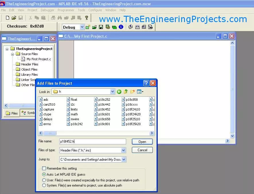
Hello friends! Today, we will create a PIC project in MPLAB and understand the files and settings needed before writing the main application. We have already covered installing MPLAB and installing the C compiler . Now we will bring those tools together in one project. The title of this older lesson refers to an MPLAB compiler, but the IDE and compiler have separate jobs. The IDE manages the project and invokes the selected language tools. The compiler and linker produce the firmware image. Understanding that distinction makes missing-file and build errors much easier to diagnose. The original screenshots show legacy MPLAB IDE with C18. We will retain that sequence for readers maintaining an older PIC18F452 project, while also explaining the corresponding decisions in MPLAB X with XC8. Do ...
Hello friends! Today, we will install a C compiler for MPLAB and make sure that a PIC project actually uses it. In the previous lesson, we covered installing the MPLAB development environment . The next step is to connect that environment to the language tools that translate our C source. The original article used MPLAB C18 and shows its historical Windows installer. Those screenshots remain useful for maintaining an older PIC18 project. For a new compatible 8-bit PIC project, MPLAB XC8 is the relevant Microchip compiler family to investigate. We will keep the two workflows distinct. By the end, you should know which compiler your project requires, how to install and select it, and how to separate an installation problem from a source-code or linker problem. We will use PIC18F452 as the ex ...
Hello friends! Today, we will install MPLAB software in Windows and prepare it for a PIC development project. In the previous lesson, we studied the PIC18F452 ports and peripherals . We now need a development environment in which to organize the source, select the device and build its firmware. The original screenshots in this article show MPLAB IDE 8.56. That is a legacy environment, while MPLAB X IDE has a different interface and installation workflow. We will explain both contexts clearly so you can reproduce an old project without mistaking its screenshots for a current installation guide. For a new setup, choose an MPLAB X release compatible with your Windows version, PIC device and programming tool. Install a suitable C compiler separately. The IDE provides the workspace, but it does ...
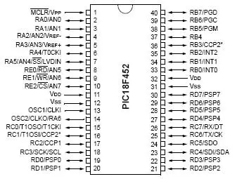
Hello friends! In the previous tutorial, we discussed getting started with PIC microcontrollers and the minimum circuit needed to run a PIC18F452. Today, we will examine its ports, timers, communication interfaces and other useful hardware functions. We will refer to the 40-pin PDIP package throughout this lesson. The signal names are more important than the physical pin numbers, because other packages can place those signals differently. Always match the package drawing to the component you actually have. The main goal is to help you allocate pins and select peripherals for a project. We will also work through timer, ADC, PWM and baud-rate calculations so the datasheet values become practical design tools rather than a list of unfamiliar abbreviations. Figure: PIC18F452 reference for port ...
Hello friends! In the previous lesson, we discussed microcontroller basics . Today, we will apply those ideas to a PIC18F452 and identify everything needed to make a simple program run on real hardware. We will use the 40-pin PDIP version of the PIC18F452, matching the original circuit in this tutorial. Our first output is an LED on RD0. Before writing the application, we will work through power, reset, the external clock, programming connections and the distinction between the IDE and compiler. The original lesson used older MPLAB tools and a socket-style programming workflow. Those are useful historical references, but a supported in-circuit programmer can program the PIC while it remains in the target circuit. The exact combination of device, programmer and software must be checked befo ...
Hello friends! Today, we are starting our microcontroller tutorial series from the basics. Before connecting a PIC, installing a compiler or writing an LED-blinking program, we need to understand what a microcontroller does and how its software interacts with an electrical circuit. Think of a project that reads a push button, changes a pattern of lights and reports its operating state. A microcontroller can coordinate those actions by repeatedly reading inputs, applying programmed rules and updating outputs. The same basic idea appears in sensor loggers, small robots, appliance controls and many other embedded systems. In this series, our detailed hardware example will be the PIC18F452. We will first learn the general ideas, then study that device's connections and development tools. You d ...
Hello friends! In this tutorial, we will learn how to use Virtual Terminal in Proteus ISIS to inspect serial data and send simple commands to a simulated circuit. It is particularly useful when working with microcontrollers, GSM modules, GPS receivers, and other devices whose behavior can be understood through a serial interface. We will begin with the simplest arrangement: a simulated microcontroller communicating directly with Virtual Terminal. Then we will return to the original article's COMPIM example, which connects a simulation to a real computer serial port. Keeping those two arrangements separate will help you choose the correct components and avoid unnecessary COM-port problems. The aim is to make serial communication visible before building a larger application around it. We wil ...
Hello friends! In this tutorial, we will design a circuit that connects a 16×2 character LCD to a PIC18F452 microcontroller in Proteus ISIS. We will select the components, wire the display, write a small program in mikroC PRO for PIC, load its HEX file into the simulated microcontroller, and display text on both rows. This is a useful first microcontroller simulation because it combines several skills in one manageable circuit: choosing the correct device, matching software pins to schematic wires, setting the clock frequency, and checking the result. If you are new to the workspace, start with our Proteus ISIS and ARES guide , then return here for the practical example. We will preserve the original PORTD connections and two-line website message. The explanation now also covers the LCD co ...