JLCPCB (JiaLiChuang Co. Limited) is a worldwide PCB & PCBA Fabrication enterprise. It is a leading company in high-tech manufacturing products specializing in PCB and PCBA production. With over a decade of experience in PCB manufacturing JLCPCB has made over a million customers through online ordering by the customers of PCB manufacturing and PCBA production.
JLCPCB is a professional manufacturer of large-scale manufacturing of PCBs, well equipment, strict management, and superior quality. It deals with the production of all types of PCBs, Stencils, and SMT.
In this article, we are going to discuss widely how the company operates its ordering system of the PCBs by their customers for production through the online booking process.
JLCPCB SMT ...
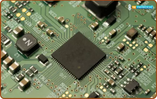
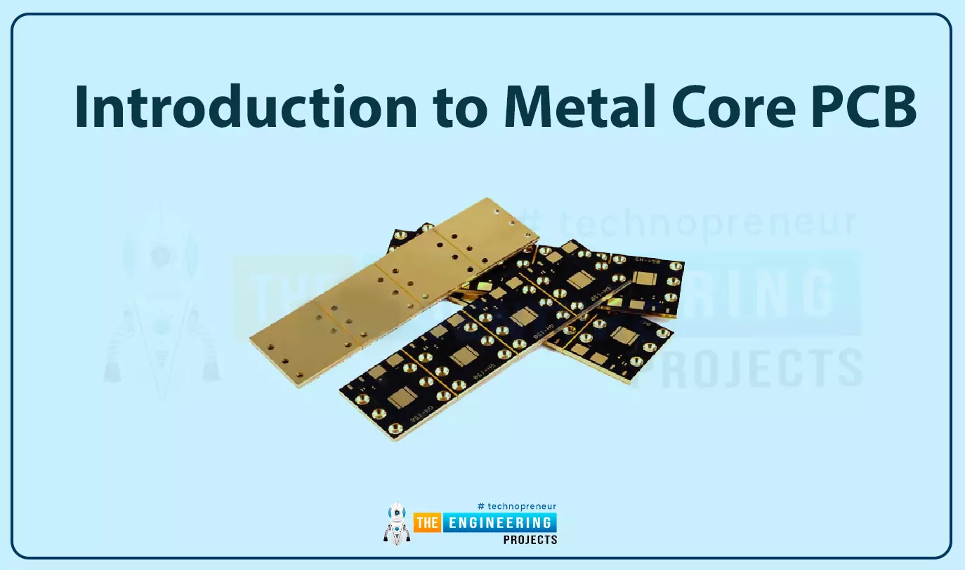
Hello everyone and welcome to this article. Previously we have been discussing different types of PCB boards and for sure we have not exhausted everything. Today we are going to focus on a very important aspect of the PCB design which is the thermal characteristics of the PCB's working environment. Up to this moment, we have interacted with boards that work best in normal working conditions. But remember there are some working conditions, that have very harsh environment such as high temperatures. Let us take for example temperature in boilers or even electric heaters. Do you think normal FR-4 boards can survive in such temperatures? Don’t you think they will melt off if exposed to high thermal radiation? Your guess is as good as mine. For us to h ...
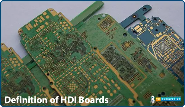
The printed circuit board is a type of plastic where electrical and electronic components lie, laminated and fixed. In modern days, there has been increasing in the complexity of electronic components and devices and this has also led to high demand for more complex PCBs that can make this achievable. This exclusive board that has been introduced in the market includes HDI, rigid-flex, Aluminium clad, buried and blind or even a blend of all the listed types.
There is a list of so many PCB types that a designer can choose for any type of electronic project ranging from single layer PCB to other complex types like the multilayered PCBs. In general, the simplest type of PCB contains copper tracks and interconnection between the elements and components on one side of the board. These types of ...
The digital industry is evolving day by day. Today, computers and phones are no longer heavy. They are sleek, powerful, and very light. Actually, some smartphones are more powerful than laptops. All this is possible because of the miniaturization of the electronic gadgets' printed circuit boards (PCBs).
Printed Circuit Boards or PCBs are categorized into several types based on design specifications, manufacturing processes, and application requirements. They are used in various sectors such as automotive, medical, defense, and other areas, you can learn more information at PadPCB.
Before you select a PCB, there are several factors you need to consider. Moreover, it is essential to seek advice from professionals. Although there are several types of ...
Hello everyone and welcome to this article which will be a great introduction to high-speed PCB design. For sure it is going to be a very interesting class. Let me start by posing a question; Is this something that you have ever come across in your world of PCB design? Where you spent too much time doing the schematics, selecting the right components, doing the footprint addition, generating the netlists, doing the proper layout and routing and sending the end product of your design to the manufacturer? At this level you might probably be designing standard types of PCB boards and if someone was to introduce a project that talks about signal integrity, reflections or even crosstalk, very much believe you will feel like a lost person. It might be s ...
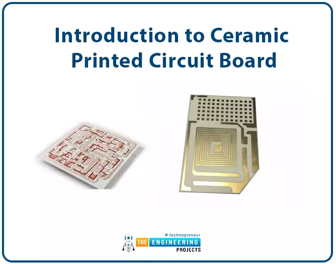
Hello friends and welcome to this article. Today we are going to have a look at the introduction to the ceramic printed circuit boards. we have previously introduced what a printed circuit board is and we noticed that it is a very important part that makes electronic circuits complete and well organized. Having that in mind, we had also discussed several materials that build up these PCBs and today our focus is on the ceramic types of PCBs.
Introduction to Ceramic Printed Circuit Board
This printed circuit board is referred to as ceramic PCB because of the substrate used in the construction of this board is made up of ceramic and it finds applications in special areas.
The process of making this board is that copper is pasted on the surface ...
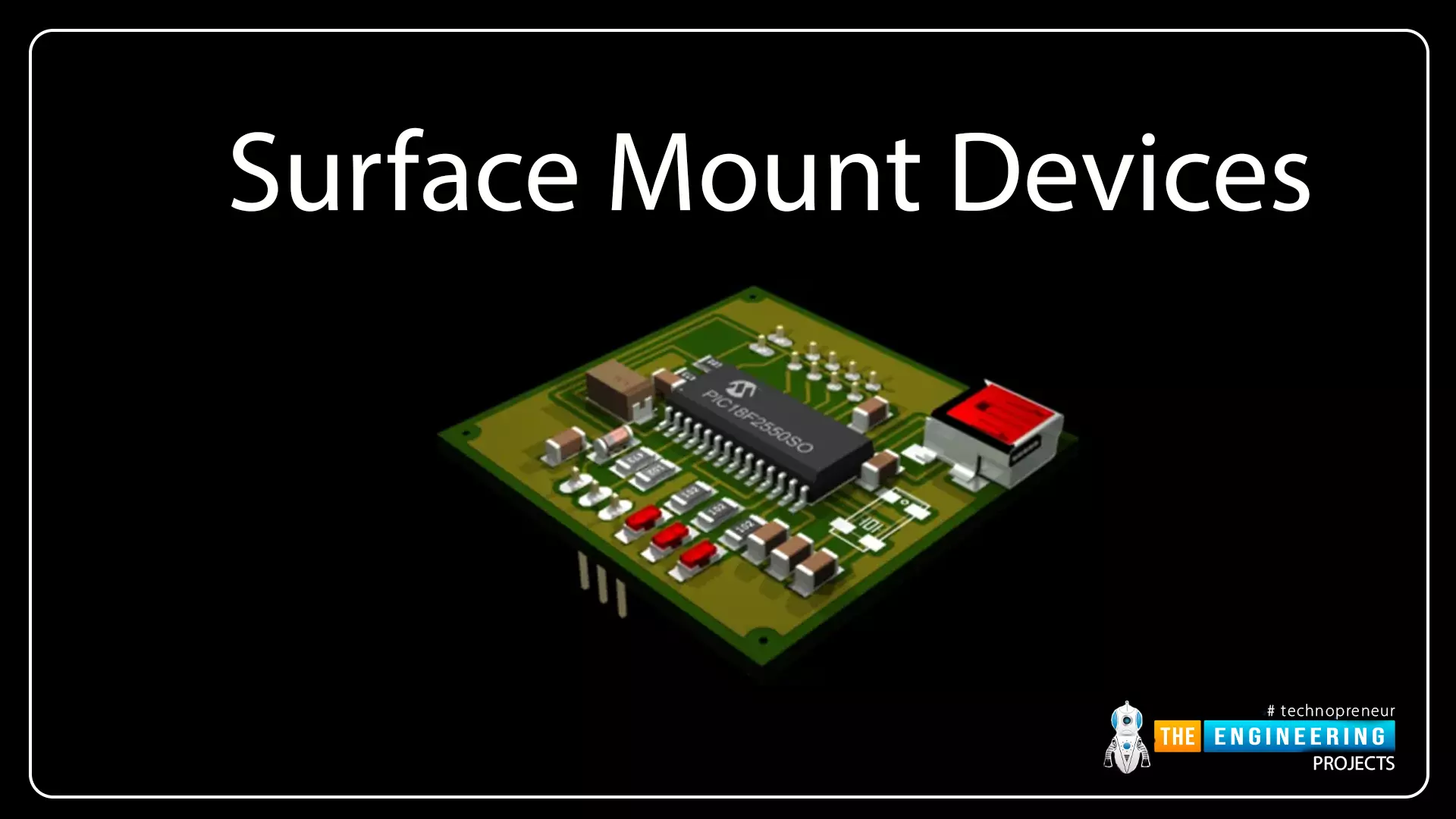
Greetings and welcome to today’s lecture. Today, we are going to focus our discussion on the Surface Mount Technology of PCB components mounting. It's our 8th tutorial in the PCB learning series and is going to be a very interesting and interactive class. In Surface-mount technology, SMT components(having small pads) are
placed on the surface of the PCB board and their pads are soldered on
the same side of the board.
As we discussed in our last lecture on Though-Hole Technology, there are two main methods used to mount components on PCB boards. We studied THT in the last lecture and today, we will focus on
Surface Mount Technology (SMT), we will discuss SMT classifications, types, applications, advantages and disadvantages in detail.
...
Hello everyone, I hope you all are doing great. Today, we are going to share the 9th chapter in the PCB learning series, where we will have a look at the difference between Through-hole and Surface-mount technology.In our previous lectures, we studied both THT and SMT methods separately and have seen that both are used for components mounting on the PCB board. So, today, we will have a look at the difference between the two techniques. So, let's get started without wasting any time.
Through-Hole vs Surface-Mount
Let us know have a look at these differences and get to know the way forward when it comes to the process of component selection whether SMT or DIP.
Definition - THT vs SMT
THT stands for through-hole technology.
In Through-hole technology, components are mounted by ...
Greetings and welcome to today’s lecture. It's our 7th tutorial in the PCB learning series. In our previous lectures, we have studied the two main types of PCB i.e. Single-sided and Double-sided PCB. Today is going to be a very interesting and interactive class about Through Hole Technology(THT), which is applied in the process of designing printed circuit boards.A PCB board has a properly designed circuit on it and it's composed of connecting traces/paths and various electronic components. The electronic components are mounted on the board in two different ways i.e. Through-hole and Surface-mount. We will cover Surface-mount in our next lecture and today, we will discuss how to mount components on PCB boards using though-hole technology.So, let's ...
Hello! Readers, I hope you are pretty good. I am here with a new article to enhance your knowledge about advanced technologies. Today, we will have a detailed overview of the Manufacturing Process of Multilayer PCB. First, we will have a look at its basic definition, why there Is a need for this new type of PCB in presence of single layer and double layer PCBs. What are the merits and demerits of multilayer PCBs and pedagogy behind the construction process of these PCBs? Let’s start to take in all information about these PCBs. I try my best to deliver all of my research capacity for doing this job.
Introduction to Multi-layer PCBs
As to the name, it's clear that multi-layer PCBs are those which have several conductive layers over substantial material which is knowns as substrate. Unlike ...