Hello friends! Today, we are going to study serial communication with an 8051 microcontroller in Proteus. We will send characters from a Virtual Terminal to an AT89C52, use those characters to control eight LEDs and send a short acknowledgement back to the terminal. If you have completed our 8051 LED blinking project , you already know how to build the basic circuit and load a HEX file. This tutorial adds a communication channel so the output changes in response to a command instead of a fixed delay. We will keep the original command scheme and project download, while correcting an important clock detail. The revised program uses an 11.0592 MHz oscillator for 9600 baud. The older screenshots show a 16 MHz crystal, so change that value and the processor clock setting when following the prog ...
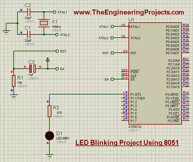
Hello friends! Today, we are going to build an LED blinking project using an 8051 microcontroller in Proteus. This is a useful first exercise because it connects a short C program with something we can immediately observe: an output pin repeatedly switching an LED on and off. We will use the AT89C52, which belongs to the 8051 family, and keep the original project's 16 MHz clock and P1.0 LED connection. I will explain the supporting circuit first, then show how to create the program in Keil, generate a HEX file and load it into the simulation. The original simulation and download remain available below. The updated example uses Timer0 for an understandable delay instead of relying on an empty software loop. That gives us a practical introduction to both digital outputs and the relationship ...
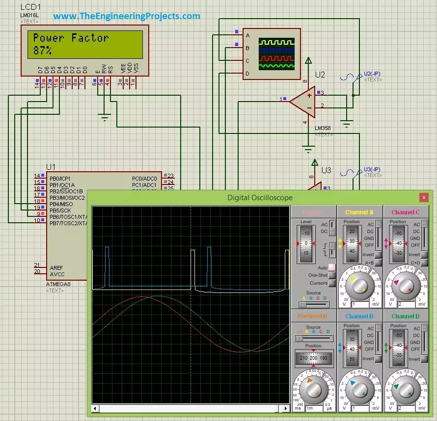
Hello friends! Today, we are going to discuss power factor measurement using a microcontroller in Proteus. We will use the ATmega8 project to understand how the timing difference between voltage and current can be converted into a phase angle, and then into a power factor reading on an LCD. I will start with the electrical meaning of power factor, because a correct calculation is useful only when we understand what it measures. After that, we will examine the zero-crossing stages, choose a timer resolution, work through numerical examples and discuss the changes needed for reliable firmware. The circuit is an educational simulation using separate signals to represent voltage and current. Its timing method is appropriate for sinusoidal waveforms. When a load draws distorted current, we need ...
Hello friends! Today we will send an SMS using a PIC18F452 microcontroller and a SIM900 modem. We will use mikroC PRO for PIC and the hardware UART, beginning with the electrical connection and then following the command exchange that submits a text message. The command sequence is related to our earlier Arduino SMS sending project . The microcontroller code changes, but the modem still needs a valid supply, compatible serial signals, network registration and correctly terminated AT commands. We will improve the original example by waiting for responses instead of assuming that fixed delays prove success. For the opposite direction, see SMS reception with Arduino and SMS reception with PIC . Figure: SIM900 carrier for the PIC SMS tutorial. What You Need for the Project PIC18F452 with its r ...
Hello friends! This page brings together our PIC microcontroller projects in a learning sequence. We will start with the controller, programming tools and a basic LED, then move through displays, inputs, analog measurements and motor-control exercises. Each linked tutorial gives you a practical next step instead of leaving you with an unrelated list of projects. If you are beginning with PIC devices, work through one small circuit at a time. Read the explanation, identify the important connections, build or simulate the example, and record what you observed. Understanding why a simple project works is more useful than collecting several HEX files you cannot adapt. Many tutorials in this collection were originally written around older PIC devices and development tools. Their core ideas rema ...
Hello friends! If you are developing an embedded project and need help with its firmware, The Engineering Projects can discuss your microcontroller programming requirements with you. Your project may involve a new prototype, a circuit that is not responding correctly or an existing program that needs a clearly defined improvement. Useful programming work starts with understanding the hardware and the required behaviour. A sentence such as “control a motor with a sensor” describes an idea, but it does not yet define a complete system. We need to know which motor, which sensor, how quickly the controller must respond and what should happen when a signal disappears. This page explains the types of work you can discuss with us, the information to prepare and the deliverables to agree before de ...
Hello friends, I hope you are doing well. In this tutorial, we will design the timing logic for a modified sine-wave inverter and study the original CD4047B and CD4017B approach. We will also develop an equivalent microcontroller timing example so you can see exactly how the positive, zero and negative intervals are produced. This article follows our tutorials on the basics of inverter topologies , the major inverter components and the pure sine-wave inverter . A modified waveform is simpler than filtered SPWM, but its harmonic content limits the loads that should use it. Figure: The comparison shows sinusoidal and stepped waveforms over a labeled 20 ms cycle. What Is a Modified Sine Wave? A modified sine wave is a stepped bipolar waveform. During each cycle, the inverter applies a positiv ...
Hello friends, I hope you are doing well. In the previous tutorials, we studied the basics of inverter topologies and the major components of an inverter . We will now connect those ideas and study how an AVR controller can create a sine reference for a pulse-width-modulated inverter. This tutorial explains the signal chain, frequency calculations, H-bridge states, LC filter and transformer. The AVR code is an educational SPWM reference generator for an ATmega16 running at 8 MHz. It is useful for simulation and low-energy waveform testing, but it must not be connected directly to power MOSFET gates. A physical inverter needs proper high-side and low-side gate drivers, hardware dead time, current limiting, voltage feedback, thermal protection and a safe PCB layout. The original project pack ...
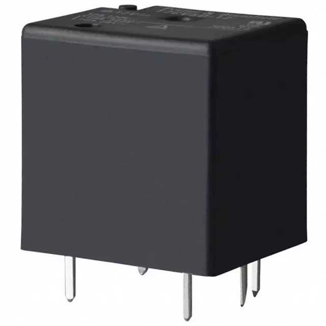
Hello friends, I hope you are doing well. In the previous tutorial, we studied the working principle of a relay . Today, we will connect a 12 V relay to a PIC18F4550 microcontroller through a ULN2003A driver. A relay coil needs more voltage and current than a microcontroller pin should provide. It is also an inductive load, so it produces a voltage transient when switched off. The ULN2003A solves these interface problems by providing seven low-side Darlington drivers and seven internal clamp diodes in one package. The key point is that the ULN2003A does not convert a 5 V logic signal into a 12 V output. The 12 V energy comes from a separate 12 V supply. A logic high merely turns on one internal driver, which connects the low side of the relay coil to ground. We will examine that current pa ...
Hello friends! In this tutorial, we will design an LED blinking project using the PIC16F877A microcontroller. It is a simple project, but it introduces several ideas that appear in almost every embedded system: configuring an I/O port, choosing an oscillator, building a reset circuit, calculating LED resistors, generating a time delay, compiling a program, and loading the resulting HEX file into Proteus. We will connect eight LEDs to PORTB and switch the complete port between logic low and logic high. Once this basic version works, you can change the output patterns and timing to create a running light, binary counter, or status display. The important objective is to understand why every connection and every program statement is present. Figure: The original simulation shows the PORTB LED ...