Hello friends! In the previous ladder-logic introduction , we built AND, OR and NOT conditions using contacts and coils. Today we will combine those building blocks to create NAND, NOR, XOR and XNOR. Each gate answers a different question about its inputs, so understanding the question is more useful than memorizing a diagram. We will retain the original X0, X1 and Y0 examples and walk through their truth tables. Then we will apply the same reasoning to a sensor-disagreement indicator and a command-feedback comparison. These examples make it easier to see why a rung that is logically correct can still be unsuitable for a particular process requirement. Before starting, remember that ladder contacts inspect Boolean data. They do not change the physical input or carry a real voltage through ...
Hello friends! In our Introduction to PLC , we looked at the controller, its terminals and the difference between a program command and an electrical output. Today we will connect those ideas using ladder logic. We will start with one input and one output, then build AND, OR and NOT conditions before adding a simple memory circuit. Ladder diagrams look like relay circuits, which makes them approachable once you understand what their symbols mean. However, the diagram is a program. A contact symbol tests a stored Boolean value; it is not a physical switch carrying voltage through the screen. Keeping that distinction clear will prevent many common wiring and programming mistakes. The retained examples use X addresses for inputs and Y addresses for outputs, following the style of the original ...
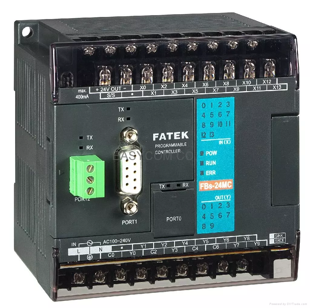
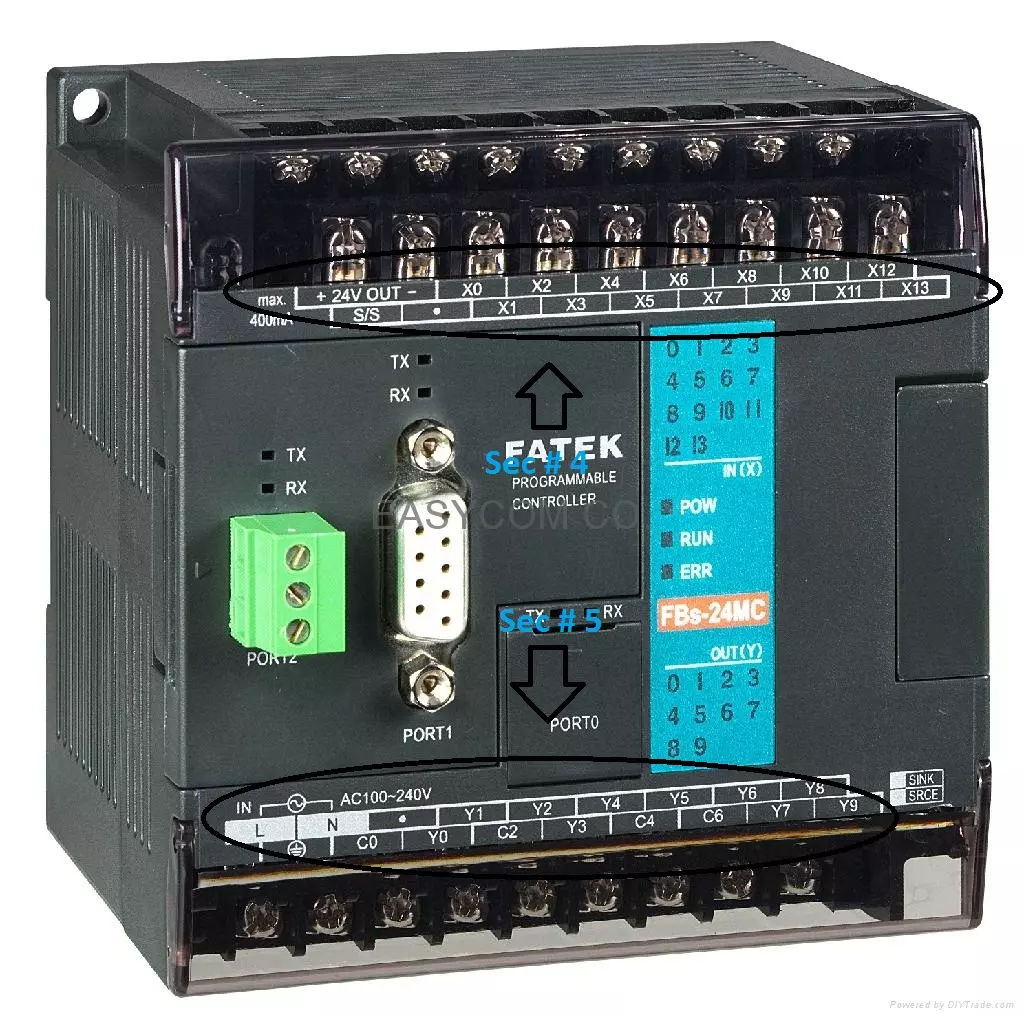
Hello friends! Today we will begin our PLC series with the hardware and operating principles of a programmable logic controller. My original introduction grew out of an automated coffee-mixing project. That is a useful example because it involves several familiar tasks: reading switches, checking conditions, opening valves and controlling how long a process runs. Before drawing a ladder program, we need to understand what happens between a sensor and an actuator. A correct program cannot repair an incorrectly wired input, an unsuitable output or a missing power supply. We will therefore work from the controller's main sections through its scan cycle, input and output connections, and a small process example. The original project identified its controller as a FATEK FBs-20MA. We will retain ...
Hello friends! This tutorial originally introduced Freebitco.in as a way to collect small Bitcoin rewards. It also suggested increasing bets after losses to earn more money. That second claim needs correcting: a betting progression cannot guarantee income, and a faucet balance is not a reliable substitute for paid work. We will keep the original topic and screenshots while examining what the numbers actually mean. The useful distinction is between receiving a promotional reward and risking money in a gambling game. A faucet may credit a small amount under its own rules. A wagering feature can then lose that amount, along with any additional funds deposited. Combining the two does not turn gambling into an investment or an engineering method for predictable earnings. In this updated guide, ...
Hello friends! Today we will study multilevel inverters, starting with the switching waveform and then looking at the circuits that produce it. An inverter converts electrical power from a DC source into an AC output. Its switches determine the instantaneous voltage, while the modulation, load and filter determine how closely the useful output follows the required sine wave. In our earlier tutorials on pure sine wave inverter design and modified sine wave inverters , the main question was how to generate the alternating waveform. Here we will introduce intermediate voltage steps and examine what they change. More steps can improve waveform quality, but they also introduce more devices, measurements and control decisions. We will compare cascaded H-bridge, diode-clamped and flying-capacitor ...
Hello friends! This tutorial continues our financial calculations in MATLAB project. We will move from expected returns and covariance to portfolio allocation, performance measurement and a complete Black–Litterman update. The central idea is to begin with a reference portfolio and the returns implied by it, then combine those returns with explicitly stated views. We must also describe how uncertain the views are. A bar chart of implied returns alone does not complete the Black–Litterman calculation. We will retain the original project's teaching sequence and historical figures while correcting its treatment of backtesting and portfolio risk. The numerical example below uses hypothetical assets and assumptions for learning. Information about the earlier implementation remains on the origin ...
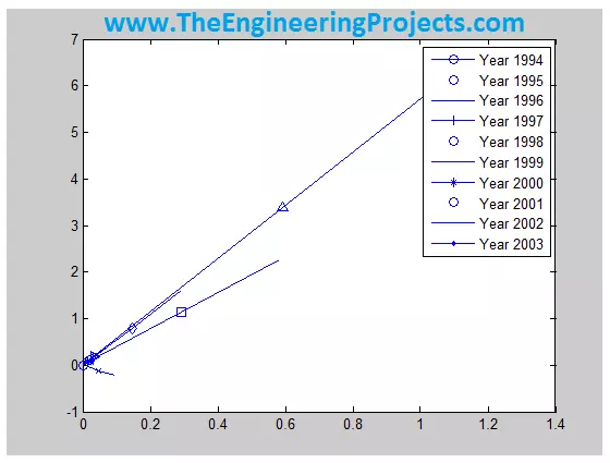
Hello friends! Today, we will work through financial calculations in MATLAB, beginning with historical market data and ending with portfolio risk-and-return plots. We will follow the original project's five stages: prepare the data, account for currency, calculate returns, estimate covariance and examine efficient portfolios. The original project compared seven market indices and explored a 3% risk-free-rate assumption. We will retain that framework, but correct several important details about exchange rates, rolling windows and portfolio interpretation. An expected return is an estimate, not a guaranteed result, and a graph is only as meaningful as the inputs behind it. This is an educational modelling example. The historical figures remain for context, while the formulas and code below e ...
Hello friends! In our previous tutorial, we installed the Arduino LilyPad library for Proteus . Now we will use that board in a small circuit with three LEDs and a pushbutton, then extend the same project to an analog level indicator. Libraries Libraries used in this tutorial Arduino Lilypad Library for Proteus: V1.0 (2014, used in this tutorial) Newer Arduino boards: UNO · Mega 2560 · Mega 1280 · Nano · Pro Mini · Mini (V4.0) Helping Tools Serial Monitor Advance : a serial terminal window for the UART of your board Serial Monitor Expert : the serial monitor with extra debugging tools LCD Library for Proteus V3.0 : 16x2, 20x4 and I2C LCDs to show your readings The basic behaviour is easy to observe: when the button is released, all three LEDs are on; when it is pressed, they turn off. This ...
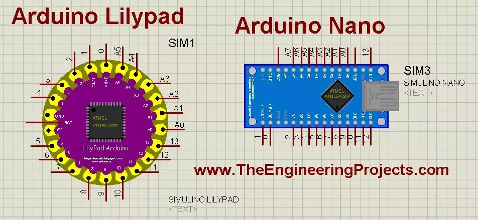
Hello friends! Today, we will install the Arduino LilyPad library for Proteus and prepare a small simulation to check the installation. This article continues our earlier Arduino library tutorial , with particular attention to the LilyPad and Nano parts included in this older library package. Updates Arduino Lilypad Library for Proteus Latest version: V1.0 (December 2014, this tutorial) Other Arduino boards: UNO · Mega 2560 · Mega 1280 · Nano · Pro Mini · Mini (V4.0) All six V4.0 boards in one package: Arduino Library for Proteus V4.0 Helping Tools Serial Monitor Advance : a serial terminal window for the UART of your board Serial Monitor Expert : the serial monitor with extra debugging tools LCD Library for Proteus V3.0 : 16x2, 20x4 and I2C LCDs to show your readings We will start by iden ...
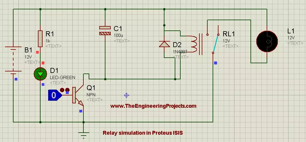
Hello friends! Today, we will learn how to control a relay in Proteus ISIS. We will begin with a simple circuit that energizes a relay coil and switches a lamp, then add a transistor so a low-voltage logic signal can control the coil. This follows naturally from our tutorials on DC motor control , stepper motor control and servo motor control . A relay is useful for switching a load on or off, but it is not the best choice for every motor-control task, particularly rapid speed control. We will keep the demonstration at low DC voltage and use a lamp as the load. The original screenshots remain below, while the connection tables explain the base resistor, protection diode and supply relationships that you should include when building a complete driver circuit. Figure: Relay control demonstra ...