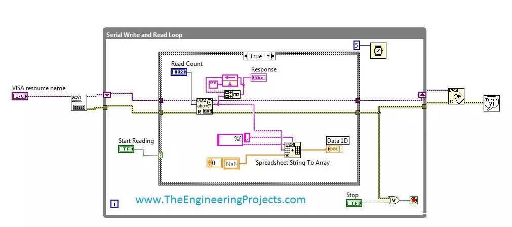
Hello friends! Today, we will receive continuous data from a COM port in LabVIEW and display both the incoming text and its individual values. This is a useful first step when connecting a microcontroller, measurement instrument or serial sensor to a computer. Our original example receives comma-separated values and places them in a one-dimensional array. We will keep that flow, but also explain how the program knows where one complete record ends. Without that step, a serial reader can appear to work during a short demonstration and then occasionally display incomplete or mixed measurements. We will start with the software and serial settings, build the front panel and block diagram, then discuss parsing, timeouts and stopping the reader cleanly. The original VI remains available near the ...
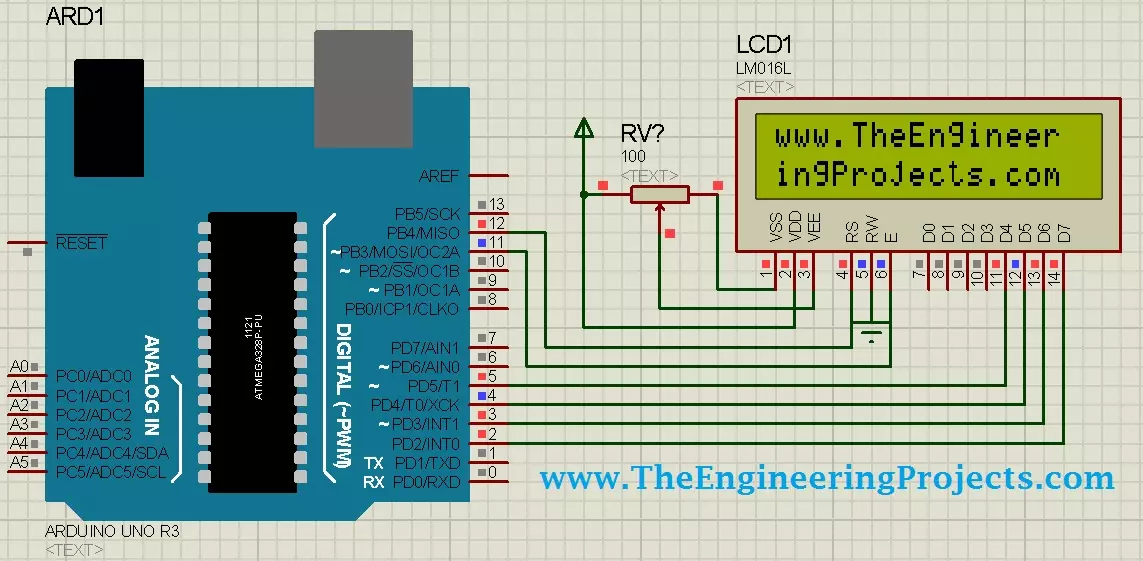
Hello friends! Today, we will design a circuit containing an Arduino UNO and a 16 × 2 character LCD in Proteus ISIS. We will connect the display, write a small Arduino sketch, compile it and load the resulting program into the simulated UNO. Our first result will be the website name displayed across two rows. Libraries LCD Simulation Libraries Latest library: LCD Library for Proteus V3.0 (October 2026): LCD 16x2, LCD 20x4 and both I2C LCDs in one library, with our own HD44780 model and an Arduino demo One LCD only? LCD 16x2 · LCD 20x4 · I2C LCD 16x2 · I2C LCD 20x4 Helping Tools Serial Monitor Advance : a serial terminal window for the UART of your board Serial Monitor Expert : the serial monitor with extra debugging tools This is a useful beginner project because the visible result is simp ...
Hello friends! Today, we will work through the EasyVR message Training Error: Recognition Failed . I originally encountered this error while training voice commands for an Arduino UNO project. Commander connected to the board, but the training attempt failed when I spoke the first command. Repeating the same attempt did not solve it. In my original setup, loading an appropriate EasyVR example and changing the shield's J12 connection from PC to SW allowed training to continue. That observation is useful, but it needs an important explanation: the correct jumper position depends on the shield revision and the communication path being used. SW is not a universal cure for every recognition error. We will separate communication problems from training and microphone problems, then return to the ...
Hello friends! Today, we will send an SMS with an Arduino UNO and a SIM900D GSM module using AT commands. We will start with the connections, check that the modem can communicate with the mobile network, and then let the Arduino submit one message. You will also learn how to tell the difference between a successful command and a message that has actually reached its recipient. Libraries SIM900 Simulation Libraries Latest library: SIM900A Library for Proteus V1.1 (October 2026) Other GSM modules: SIM800L · SIM800C · SIM808 Helping Tools Serial Monitor Advance : a serial terminal window for the UART of your board Serial Monitor Expert : the serial monitor with extra debugging tools LCD Library for Proteus V3.0 : 16x2, 20x4 and I2C LCDs to show your readings The SIM900D handles the radio conn ...
Hello everyone! Today we will explore the Arduino Yún and connect it to a local network. This board combines familiar Arduino programming with an onboard Linux system, allowing a project to read physical inputs and communicate with network services without keeping a desktop computer attached. Libraries Arduino Simulation Libraries Arduino boards: UNO · Mega 2560 · Mega 1280 · Nano · Pro Mini · Mini (V4.0) All six V4.0 boards in one package: Arduino Library for Proteus V4.0 Helping Tools Serial Monitor Advance : a serial terminal window for the UART of your board Serial Monitor Expert : the serial monitor with extra debugging tools LCD Library for Proteus V3.0 : 16x2, 20x4 and I2C LCDs to show your readings We will start by understanding its two processors, then follow the original illustra ...
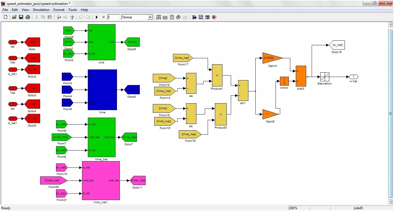
Hello friends! Today we will study sensorless speed estimation of an induction motor in MATLAB and Simulink. We will follow the original project's adaptive-estimation approach, beginning with the motor equations and then connecting those equations to the illustrated simulation blocks. The aim is to estimate rotor speed from electrical quantities rather than feed a measured shaft-speed signal into the estimator. In simulation, the motor model still provides a true speed for comparison. Keeping that reference separate from the estimator inputs is essential: otherwise, a model can appear sensorless while quietly using the answer it is supposed to estimate. The original project was developed in the MATLAB 2010 era and described as used with later 2012 and 2013 releases. The diagrams below docu ...
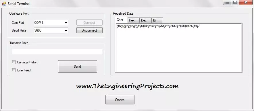
Hello everyone! Today I am sharing the Serial Terminal software developed in Visual Basic 2010. It provides a simple window for opening a COM port, sending text, and viewing received data in character, hexadecimal, decimal, and binary forms. We will download the original package and work through a practical communication session. The earlier Visual Basic serial-port tutorial introduced basic transmission and reception. This terminal adds convenient display tabs and optional carriage-return and line-feed characters. Those small features are useful when a microcontroller appears to receive your command but does not respond as expected. We will explain the original interface as it is shown, then cover connection settings, line endings, data representation, and troubleshooting. The download re ...
Hello friends! Today we will add a delay to a Visual Basic application in Visual Studio 2010. The short answer is System.Threading.Thread.Sleep(1000) for a one-second pause, but choosing where to put that statement is just as important as choosing the number. I originally needed this while spacing readings in a database project. That is a useful example because a program often needs to wait between operations while its window remains responsive. We will begin with the simple pause, then build a timer-based Windows Forms example that allows the user to cancel while waiting. The examples retain the Visual Studio 2010 and Visual Basic context. We will distinguish features available in a typical .NET Framework 4 project from later asynchronous programming features, and explain why a fixed dela ...
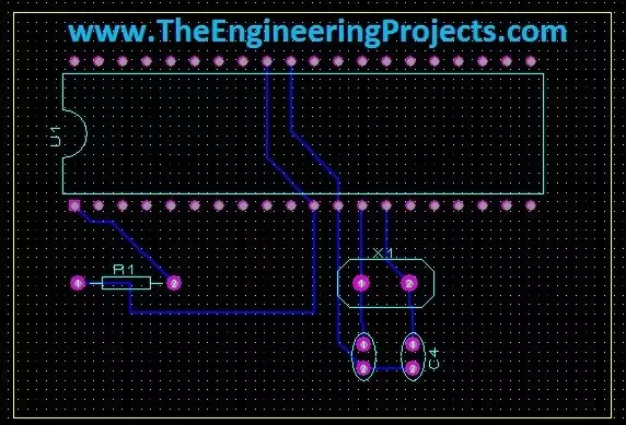
Hello friends! Today we will move from a circuit diagram to a printed circuit board using Proteus ARES. We will use a small PIC16F877A circuit so that placement, connectivity, and routing remain easy to follow. The same sequence of decisions applies when you later design a larger board. Proteus schematic capture describes which component pins belong to each electrical net. PCB layout turns those connections into physical pads and copper tracks. A completed route is useful only when the footprint, pin mapping, power connections, and manufacturing rules are also correct. We will follow the original illustrated workflow: prepare the schematic, transfer its connectivity, define the board edge, place components, and route the board. We will then add the checks needed before sending a design for ...
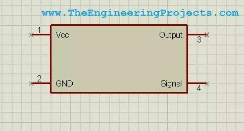
Hello friends! Today we will design a custom component in Proteus ISIS. This is useful when you need to document a circuit but cannot find the exact module, connector, or device in your installed library. We will draw a simple four-pin symbol, define its connections, and save it so that it can be placed like other library parts. The original purpose of this tutorial is schematic presentation, and we will keep that approach. A clear custom symbol helps another person understand how your project is connected. We will also discuss the extra information required before the same part can be used for PCB layout or electrical simulation. Our example is a fictional device named Test Device with VCC, GND, OUTPUT, and SIGNAL connections. These names let us practise the workflow without claiming to r ...