Hello friends! This page organizes our Arduino projects into a practical learning path. We will begin with board setup and a first sketch, then move through displays, sensors, communication and combined applications. The aim is to help you choose the next useful exercise instead of searching through an unrelated collection of links.
Work through the projects actively. Read the circuit, predict the result, run a small example and explain any difference you observe. You can also explore our Arduino projects for beginners and the corresponding PIC microcontroller project guide when comparing learning paths.
The collection includes historical boards, software and simulation packages. Keep each tutorial's exact hardware and version requirements in mind. An example written for a classic Uno or an older wireless shield does not automatically apply to every newer board carrying the Arduino name.

Plan Your First Arduino Projects
| Stage | First objective | What to understand before moving on |
|---|---|---|
| Setup | Upload a simple sketch | Board, port, power and build messages |
| Input and output | Read an input and control an indicator | Pin mode, signal levels and current limits |
| Measurement | Display a sensor reading | Units, timing, calibration and invalid data |
| Communication | Exchange a defined message | Framing, addresses, timeouts and replies |
| Integration | Combine working subsystems | Shared resources and failure behavior |
Use the official Arduino site for board documentation and software references alongside these project explanations. Identify the exact board revision, because supply limits, processors and peripheral assignments vary across the platform.
Learn the Software and Programming Basics

- What Is Arduino? introduces the relationship between a development board, its microcontroller and the sketch you upload. Begin here if those terms are unfamiliar.
- Arduino and Raspberry Pi Compared helps separate microcontroller tasks from operating-system tasks. Choose from the project's timing, interfaces and software needs, not a universal winner.


- Arduino Drivers in Windows explains device recognition and the upload connection. Some boards use built-in operating-system support; others require a driver for their particular USB interface.
- Getting Started with Arduino Software introduces editing, selecting a board and compiling. Read build errors before changing hardware, because compilation and uploading are separate stages.


- Getting Started with Arduino Programming develops the basic sketch structure. Understand which work happens once in setup and which work repeats in loop.
- Obtaining an Arduino HEX File is useful for compatible simulations and programming workflows. Confirm that the exported binary matches the selected target and latest source.


- Uploading an ATmega328 Bootloader covers a particular programming workflow. A bootloader supports serial uploading, but direct ISP programming does not inherently require one.
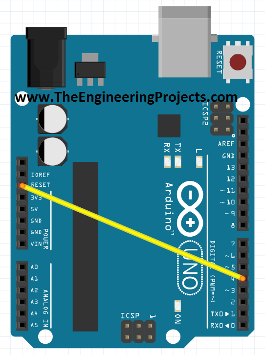
- Resetting Arduino Programmatically discusses restart behavior. Reset methods are architecture-dependent; jumping to an address is not necessarily equivalent to a complete hardware reset.
Identify the Board You Are Using
Read the introduction for your exact board before wiring peripherals. The tutorials below concern particular classic designs; names such as Uno and Nano now describe families with more than one processor or electrical arrangement.
- Arduino Uno Introduction is a starting point for the classic board used throughout many projects. Check the board revision and actual processor marking.
- Arduino Nano Introduction discusses the compact classic format. Similar physical dimensions do not guarantee identical processors, bootloaders or USB interfaces on every Nano-family board.


- Arduino Pro Mini Introduction explains a compact board commonly used with an external programming adapter. Match voltage and clock variants before connecting that adapter.
- Arduino Mega 2560 Introduction explores a board with more I/O and interfaces. Extra pins do not remove the need to track peripheral assignments and current limits.


- Arduino Due Introduction covers a different processor architecture. Review its voltage requirements instead of copying classic Uno wiring without checking compatibility.
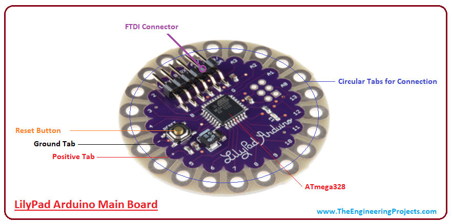
- LilyPad Arduino Introduction introduces a form intended for wearable projects. Conductive-thread resistance, insulation and the exact LilyPad variant become part of the design.
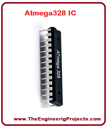
Introduction to ATmega328 provides context for a processor family used in several classic boards. Distinguish the precise part, such as ATmega328P, from a general family name when selecting a compiler target or programmer setting.
Use Simulation and Libraries for Defined Questions
Simulation helps inspect firmware logic and modeled signals before assembling a circuit. It does not guarantee that an arbitrary library supports every peripheral or that a hardware power supply will behave like an ideal schematic source.
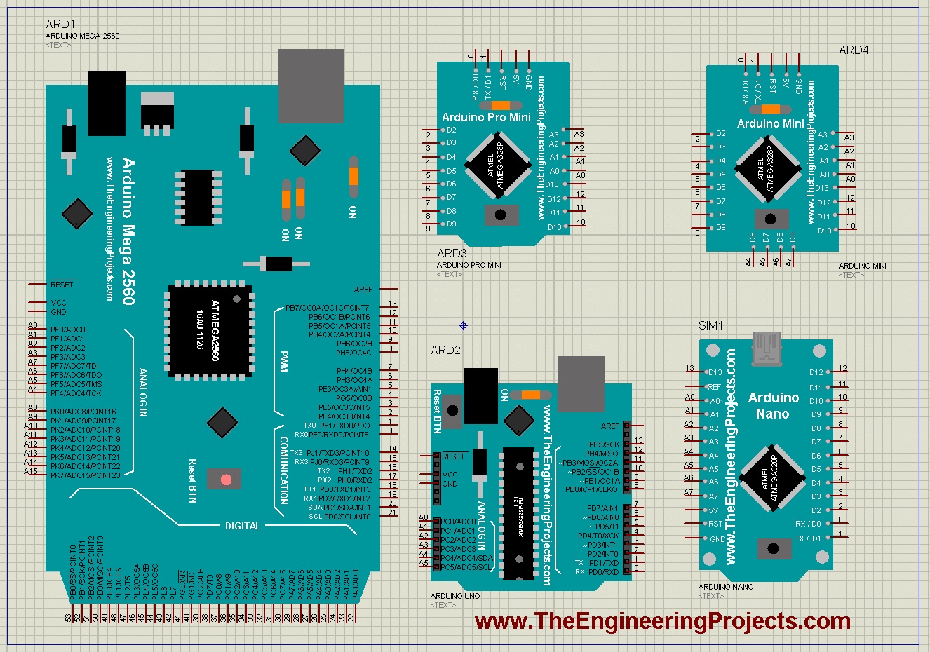
- Arduino Library for Proteus provides board models for the simulator. Check the version and included boards rather than assuming that every Arduino project can be simulated.
- Proteus Libraries for Engineering Students collects additional models. Read each model's supported behavior and installation instructions before relying on it.
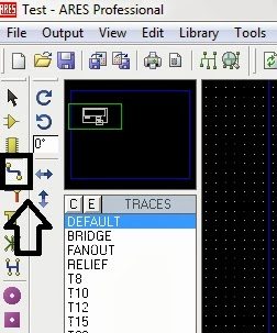
Arduino Uno PCB Design for Proteus ARES introduces board layout material. A PCB layout and a firmware simulation model solve different problems; inspect footprints, connectivity and manufacturing requirements separately.

LilyPad Library for Proteus supports the corresponding simulation exercises. Use the processor and clock assumptions required by that model, not those of an unrelated Uno project.
Build Inputs and Displays First
A display and a readable diagnostic channel make later projects easier to understand. Establish them with known values before asking them to report a sensor that may itself be incorrectly connected.
- Using Arduino Serial Read introduces incoming bytes. Add message framing and input bounds when progressing from one character to longer commands.
- LCD Interfacing with Arduino in Proteus develops a visible output. Check contrast, signal order and display geometry before diagnosing application logic.
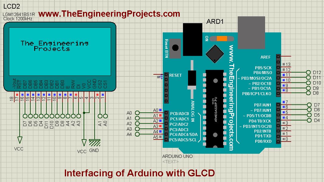
- Keypad Interfacing in Proteus develops matrix scanning and key reporting. Test held keys, release and bounce rather than only one clean press.
- Displaying ADC Values on an LCD joins input acquisition to presentation. Show raw codes first, then explain the reference and scaling used for voltage.
- Seven-Segment Interfacing in Proteus builds a single-digit counter. The supplied basic library handles decimal digit characters, not arbitrary alphanumeric text or a multi-digit controller.
- Scrolling Text on an 8 x 8 LED Matrix introduces patterns and refresh behavior. Check driver current and timing when moving from a modeled display to hardware.
Measure Distance and Temperature
- Ultrasonic Sensor Simulation in Proteus uses a model stimulus to exercise distance-reading code. A test input is not a physical acoustic scene.
- Ultrasonic Sensor Interfacing with Arduino develops the trigger-and-echo measurement on hardware. Include a timeout and distinguish a missing echo from zero distance.
- Multiple Ultrasonic Sensors with Arduino adds sequential acquisition and discusses interference. Several sensors can hear one another, so separate GPIO pins do not guarantee independent measurements.
- DS18B20 Temperature Interfacing introduces the 1-Wire temperature workflow. Check power mode, conversion timing and error handling before interpreting extra decimal places as accuracy.
- DS18B20 Simulation in Proteus explores the temperature interface in a modeled environment. Keep model controls distinct from the behavior of a physical probe.
- LM35 Interfacing with Arduino develops analog temperature scaling. The reference voltage and sensor transfer characteristic both contribute to the resulting measurement.
For a distance calculation, an assumed sound speed of 0.0343 cm per microsecond gives distance = echo duration × 0.0343 / 2. The division by two accounts for the outward and return journey. Temperature, target geometry and missing echoes still affect the result.
Explore Detection and Identification
- PIR Sensor Interfacing explores a motion-related output. A basic PIR result should not be treated as a perfect count of people or proof that an unchanging room is empty.
- Flame Sensor Interfacing demonstrates response to an optical stimulus. A classroom sensor exercise is not a certified fire-detection system.
- RFID RC522 Interfacing introduces card communication. Reading an identifier is a different task from designing a secure access-control credential system.
Define what the input actually establishes. Detection thresholds, placement and environmental interference determine whether an application can draw the intended conclusion. Label uncertain or invalid data explicitly instead of forcing every sample into a confident decision.
Add Wireless Communication
- NRF24L01 Interfacing with Arduino develops a transmitting and receiving pair. Match addresses, channels, data settings and supply requirements at both ends.
- NRF24L01 Response Timeout Troubleshooting examines a common failure. A timeout is a symptom that can involve power, configuration or missing replies, not one universal fault.
- HC-05 Bluetooth Communication introduces a serial bridge to a compatible host. Verify the host's supported Bluetooth mode and the module board's electrical interface.
XBee project sequence
- Introduction to XBee Modules identifies the radio concept and family-dependent configuration.
- XBee Interfacing with a Computer establishes a diagnostic connection before adding application firmware.
- XBee Interfacing with Arduino brings the radio link into a microcontroller project.
Across these projects, successful transmission is not the same as confirmed application action. Give messages a format, limit their size and decide what should happen when a reply does not arrive.
Work with GSM Messaging
- Send SMS with Uno and SIM900D follows an AT-command exchange. Check modem power bursts, UART levels, registration and the command's final result.
- Receive SMS with SIM900 and Arduino introduces incoming-message handling. Parse complete responses and notifications instead of relying on fixed character positions.
SIM900-family projects depend on a compatible cellular network and service. Confirm local support before planning around this older technology. A message received from a particular number is also not automatically sufficient authorization for a consequential control action.
Voice Recognition and Camera Projects
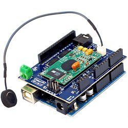
- Voice Recognition with EasyVR introduces the recognition project and its basic workflow.
- Getting Started with EasyVR Commander covers the configuration and training tool used with the shield.
- EasyVR Shield with Arduino Uno connects recognized command identifiers to application logic.
- EasyVR Training and Recognition Errors helps investigate failures without assuming that every spoken phrase must be recognized.
Keep recognition results separate from output permissions and output duration. A recognition demo becomes easier to inspect when each accepted command has a clearly bounded effect and a visible confirmation.
- Getting Started with Pixy Camera introduces the original camera workflow.
- Installing PixyMon covers the matching configuration application.
- Updating Pixy Firmware explains firmware loading; select a release compatible with the exact camera generation.
- Training Pixy with a Computer develops color-signature recognition and observation.
A trained color signature depends on lighting and the scene. Test it with expected backgrounds and object positions before treating the camera output as a reliable control input.
Control Motors with Suitable Drivers
- Servo Control in Proteus introduces repeated position-command pulses. Supply the motor independently of the signal pin's tiny current capability.
- DC Motor Direction Control develops a direction-control interface. Check the driver and motor power path rather than connecting a motor directly to GPIO.
- DC Motor Speed Control explores PWM commands. Duty ratio is a control input, not a universal linear measurement of shaft speed.
- Stepper Direction Control studies phase sequence and its relationship to rotation direction.
- Stepper Speed Control relates step timing to motion while considering acceleration and missed steps.
For an assumed 200-step-per-revolution motor with no microstepping, 400 commanded steps per second correspond to 2 revolutions per second, or 120 rpm. That is a commanded rate; insufficient torque or excessive acceleration can prevent the rotor from following it.
Combine the Interfaces into Applications
- Traffic Signal Control with Arduino is a state-sequencing exercise. Treat it as a classroom model, with explicit transitions and startup states.
- Intelligent Energy Saving System combines occupancy-related inputs with outputs. Consider timeouts and false detections before changing a load state.
- USB Communication between Android and Arduino explores host-device interaction. Confirm USB roles and support on the particular phone and board.
- Home Automation with XBee and Arduino combines wireless commands and load interfaces. Define what happens when the radio link fails.
- GSM-Based Home Security Exercise combines several sensor inputs and messaging. It illustrates integration rather than guaranteeing complete protection.
Network and Arduino Yún Projects
- Getting Data from a Web Server with Arduino Wi-Fi introduces a client request and response. Match the library to the actual shield and review its protocol capabilities.
- Getting Started with Arduino Yún explains the board's microcontroller and Linux sides.
- Accessing Yún Linux with PuTTY develops SSH access, filesystem navigation and a small script.
Network operations can take far longer than reading a GPIO pin. Use timeouts and a clear data format so a slow server does not block unrelated application work indefinitely. On the Yún, define which processor owns each task and how results cross between them.
Review a Project Before Expanding It
Keep a record of the exact board, library versions, wiring and program file. When adding a peripheral, check whether it needs a pin already used for a display, UART, SPI device or timer function. Individually working examples may conflict when combined.
Calculate a simple power budget. For example, five indicator LEDs at an assumed 4 mA each need 20 mA in addition to the controller and peripherals. Motors and radios can introduce larger transient demands that a steady average does not reveal.
For an ideal classic 10-bit ADC with a 5 V reference, one code interval is 5 / 1024 = 4.883 mV. Use that calculation to distinguish resolution from accuracy. More decimal places on an LCD cannot remove reference error or sensor uncertainty.
Test normal operation, startup, disconnected inputs and communication timeouts. Record invalid readings separately from legitimate zeros. A useful project report explains both a successful result and the boundaries under which that result was obtained.
Turn Separate Examples into One Responsive Application
Suppose a project reads a sensor, refreshes a display and sends a wireless status message. Give each activity its own schedule and let the latest valid measurement carry a timestamp. The display can then show that measurement without forcing a new sensor conversion every time it redraws.
Write down the worst-case waiting time of each operation. A 30 ms sensor timeout followed by a 2 second network timeout can make an otherwise short loop unresponsive for more than two seconds. That delay matters if a button or output needs attention sooner.
Use a state machine or a suitable asynchronous interface when necessary, and keep every retry bounded. A disconnected peripheral should produce a visible fault state rather than an endless loop that prevents the rest of the project from operating.
Also decide which values persist after an error. Showing the last known temperature can be useful if it is clearly marked stale; silently presenting it as a new measurement is misleading. For an output, choose the timeout behavior from the application instead of treating every failure as a valid zero command.
This integration plan is the bridge between following tutorials and designing your own system. It gives each component a defined role and makes the combined behavior explainable when one part becomes unavailable.
Frequently Asked Questions
Which project should I start with?
Start with board setup and a small input/output example, then add a readable diagnostic channel. Choose a sensor project after you can upload and interpret basic behavior confidently.
Must I simulate every project first?
No. Simulation is useful when an appropriate model exists and answers your question. A simple low-voltage breadboard experiment can also be an effective learning step.
Can I combine two sketches by copying their loops together?
Not reliably. Review pin ownership, timing, libraries, memory and communication first, then design one coordinated application structure.
Are all boards called Nano or Uno electrically identical?
No. Check the specific revision and processor. Similar names and footprints do not establish compatible voltages or peripherals.
How should I ask for help with a project?
Provide the board and module identities, relevant wiring, a small reproducing sketch and the exact error or observed behavior. Those details make practical troubleshooting possible.