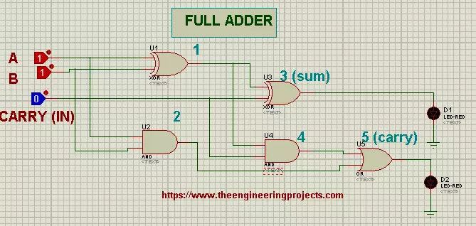
Hello Learners! I hope you are doing great. Welcome to The Engineering Projects. In our previous lecture, we discussed How to design Half Adder with Universal Gates. In today's tutorial, we are going to design Full Adder with Logical Gates.
In today's tutorial, we will learn the complete information about:
What is Adder?
What is Full Adder?
How is the Truth Table of Full Adder?
How can we design Full Adder in Proteus ISIS?
What are the uses of Full Adder?
What is Adder?
Recalling from our previous lectures:The Adders are simple Logical Circuits that take the bits in as the input, sum the bits together and generate the sum and the carry at the output.Adders are present in computer architecture, mainly to control the ...
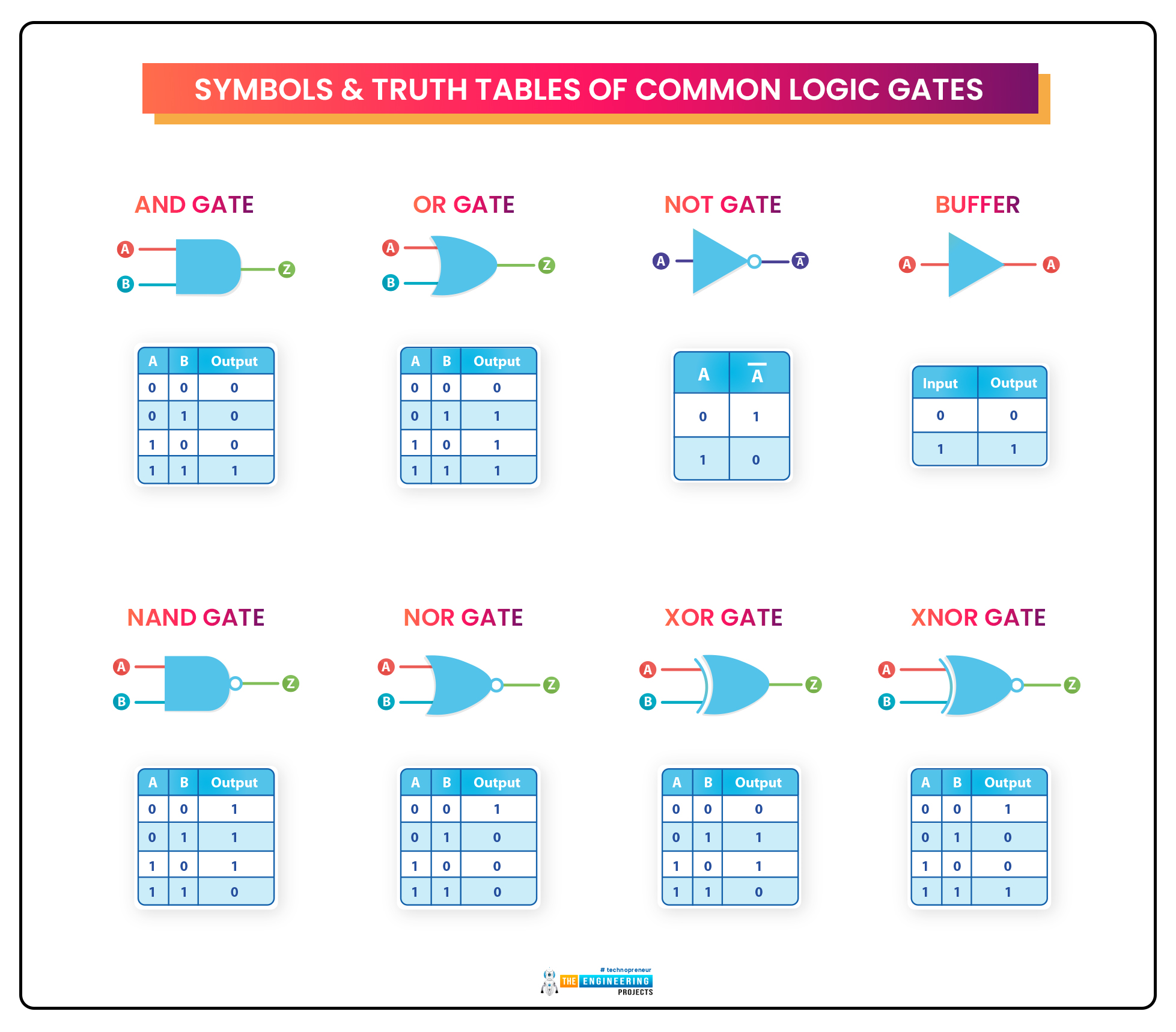
Hello Mentees! I hope you all are doing well. In today's article, we'll learn about the very basic pillar of Digital Logic Circuits i.e. Logic Gates. As we know, the digital world depends on Boolean digits either 0 or 1. So, there's always a need to perform different operations on these boolean numbers i.e. addition, subtraction, multiplication, shifting etc. In order to perform these operations on the binary signals, we use Digital Logic Gates in DLD circuits.So, let's have a look at What is a Logic Gate:What is a Logic Gate?
Logic Gates are designed to perform a specified operation(i.e. addition, bit shift etc.) on the input signals and generate the output signal.
For example, a simple NOT gate takes a single binary input and returns its inverse in the output, i.e.If Input is 0, the Ou ...
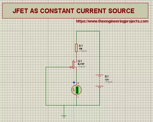
Hi Pupils, Welcome to another Experiment of Proteus at The Engineering Projects. Previously, we saw what are the Junction Field Effect Transistors. Today we'll learn about some of the applications of Junction Field Effect Transistors.
Just before the Experiment, it is useful to revise that:
Transistors are three terminal, unipolar Devices. The terminals of Junction Field Effect Transistor are named as :
Drain
Source
Gate
The Gate Terminal is common to both Source and Drain.
Prior to start, let's clear some Concepts about Junction Field Effect Transistor.
Resistor
Resistor is an electrical device. we define the resistors as:
"A Resister is a two terminal Passive electrical device that shows the electrical resistance and is useful in almos ...
Hi mentees, we are here with a new tutorial. I hope you all are fine. So far, we have been designing combinational circuits i.e. Adder, Subtractor, Multiplexer etc. using logic gates. But from today onward, we will design sequential circuits using logic gates i.e. Latches, Flip Flops etc. Let's quickly recall what's the difference between combinational & Sequential Circuits:
Combinational Circuits:
Combinational circuits only use the current state of the input values to generate the output.Examples of DLD Combinational Circuits are: Adders, Subtractors, Multiplexers etc.
Sequential Circuits
Sequential Circuits use both the current & previous states of the inputs to generate the output.Examples of DLD Sequential Circuits are: Latches, Flip Flops, Timers, Counters etc.
Digital M ...
Bonjour trainees!!! Welcome to the Engineering projects, We hope you are doing great. In our previous lecture, we discussed the first type of clippers in detail i.e. Series Clippers. Today, we are going to discuss the next two types of Clippers i.e. Shunt Clippers and Dual Clippers. Here are the types of Clippers from the last lecture:
So, today, we are going to cover the below concepts:
what is a Shunt Clipper?
Types of Shunt Clippers
Implementation of shunt Clippers in Proteus ISIS.
Dual Clippers basics.
Implementation of Dual Clippers in Proteus ISIS.
So, let's get started:
What is a Shunt Clipper?
In Shunt Clippers(Parallel Clippers), the diode is connected in Shunt(Parallel) to the input signal source & the load resi ...
Hey buddies, hope you all are fine. In our previous tutorial, we studied Half Wave Rectification and have seen that it rectifies the half wave of the AC signal. Today, we are going to study Full Wave Rectification to rectify the complete AC source. We will design the simulation of the Full Wave Rectifier in Proteus software. So, let's get started:
What is Full Wave Rectification?
A comprehensive definition of full-wave rectification is:
Full-wave rectification
is a process to convert both cycles(positive & negative) of input(sinusoidal) wave to pulsating DC
(Direct current).
We have studied in the previous lecture that Half Wave Rectifiers are used to convert only one cycle(either positive or negative) of an AC signal into a DC signal, thus dissipating the 50% energy of the o ...
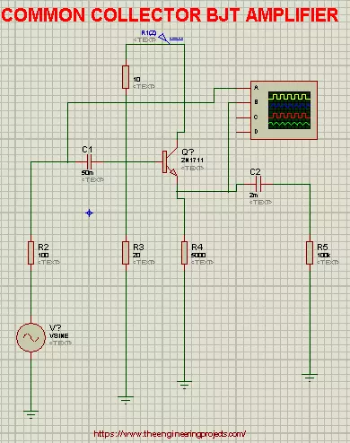
Hi Mentees, Welcome to a new tutorial at The Engineering Projects. Today You will unearth about Common Collector bipolar Junction Transistor Amplifiers. Before this, we learnt about two types of Configurations of Transistors named Common Emitter BJT Amplifiers and Common Base BJT Amplifiers.
In this tutorial We'll discuss about:
Introduction of Common Collector BJT Amplifier.
Basic Concepts for the Common Collector BJT Amplifiers.
Implementation of Common Collector BJT Amplifiers in Proteus ISIS.
Characteristics and advantages of Common Collector BJT Amplifiers.
So that, you can get the best understanding about the topic and its practical implementation.
Introduction
1st of all, We'll have a brief definition of the Common Collector Ampl ...
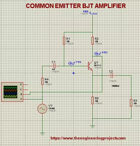
Hi Learners, I hope you are doing good. This lesson is about implementation of one of the types of Amplifiers i.e, Common Emitter BJT Amplifier. But, prior to this, we'll revise some basic concepts so that it will be easy for you to understand the roots of the Experiment.
We'll talk about:
What are Common Emitter Bi-Junction Transistors.
Concepts of Common Emitter Bi-Junction Transistors.
Implementation of Common Emitter BJT Amplifiers in Proteus ISIS.
Why we use Common Emitter BJT in Amplifiers.
What are Common Emitter Bi-Junction Transistors
There are three types of Configurations of a transistor named:
Common Emitter Configuration
Common Base Configuration
Common Collector Configuration
We chose the Common Emitter Configurati ...
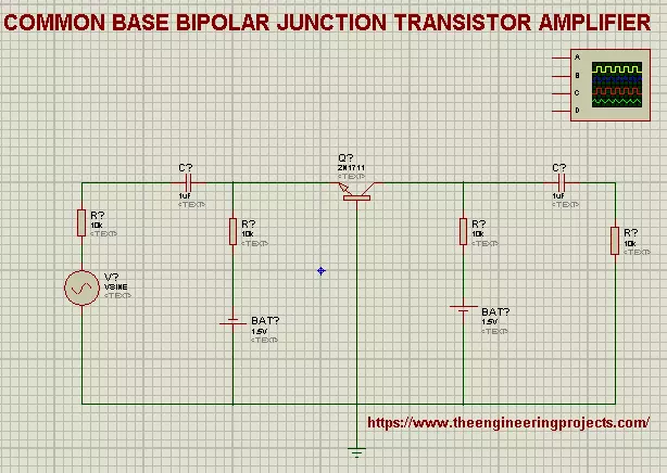
Hi mentees, Welcome to The Engineering Projects. If you are seeking for the Practical Implementation of Common Base bipolar Junction Transistor amplifier then you clicked at the best website because we'll cover the basic concepts and the procedure step by step.
So, Lets start the learning.
What is Common Base BJT Amplifier?
The precise definition of the Common Base BJT Amplifier is:
"The type of Bipolar Junction Transistor Amplifiers in which Base is Common to both emitter and Collector and Current gain is taken from the Base is called Common Base bipolar Junction Transistor Amplifiers."
Recall that a transistor has three regions i.e, Base, Collector and Emitter. Hence we design our Circuit in such a way that we get the output of current from ...
Hello friends, I hope you all are having fun. In today's tutorial, we will have a look at Series Clippers & their types in detail, we will also implement the simulations of Series Clippers in Proteus software. In the next article, we will discuss the next two types of Clippers i.e. Shunt Clippers & Dual Clippers. Today, We are going to learn:
What is a Clipper?
What are the types of Clippers?
Series Clippers Simulations in Proteus.
So, let's get started:
What is a Clipper???
Clipper (also known as Limiter) is an electronic circuit, which clips or limits the amplitude(positive, negative or both) of an AC source wave.
Diodes are normally used for designing Clippers and such circuits are normally referred as Diode Clipping Circuits (Diode Limiting Circuits).
...