Rigid Flex PCB


It makes use of flexible layers of substrate material which are connected together using a pre-preg film which is then attached to a rigid board, keeping the precision and accuracy intact. I'll try to cover each and every aspect related to rigid-flex PCB so you find all information in one place. Let's dive in and explore what is it about and what are its main applications?
What is Rigid Flex PCB?
- Before we explore what is Rigid-Flex PCB, we must have a clear idea of what is PCB?
- PCB is an acronym of Printed Circuit Board which uses conductive traces and paths incorporated on a single board to electrically connect different components on the board.
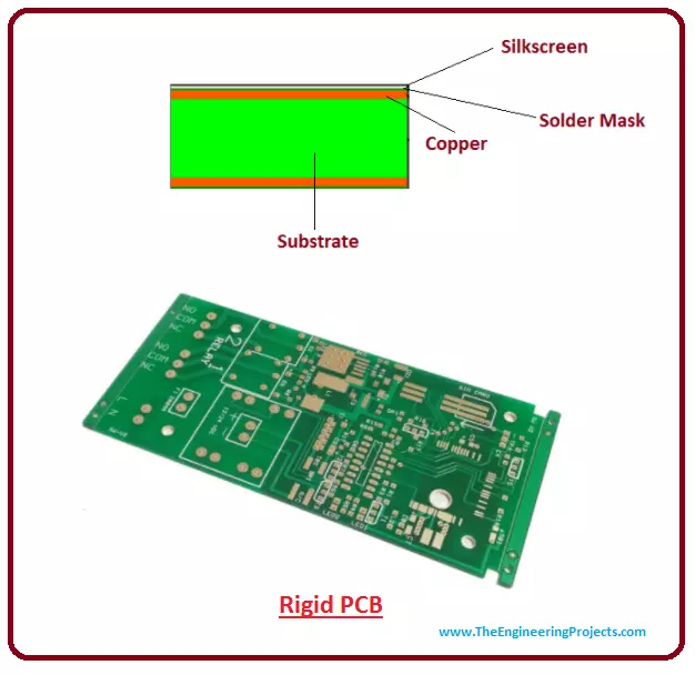
- Copper foil is used to provide a conductive path which is laminated on a substrate material that is often composted of epoxy resin.
- Rigid Flex PCB is a combination of rigid and flex circuits which provide both flexibility and strength to the board.
- It is mainly composed of a flexible layer of substrate material which is joined together with the help of pre-preg bonding film and then attached to a rigid circuit board.
- This unified circuit is connected with the help of through holes and it ideally manipulates the advantages of both rigid and flex circuits where rigid portion provides a reasonable area for component density and a flexible portion is used for maintaining a connection with the rigid portion.
- The main reasons for creating rigid flex circuit are improved flexibility, reduced flex thickness and lower part cost.
- In the past, most professionals developed a rigid-flex design by joining two rigid boards with the flex cable.
- This idea was acceptable for short-run designs, also this approach involved the cost of connectors and the cost of assembling connectors on the board.
- Also joining the rigid board with flexible connectors result in the formation of electrically cold joints, which leads to malfunction. This resulted in the development of rigid-flex boards.
- Rigid-Flex circuits come with high component density, and are prerequisites for the applications where using flex and rigid circuits separately are unable to fulfill the requirement of the project.
- Rigid and Flex PCB are joined together to shape multiple designs, where rigid part provides extra support and flex circuit provides a mix of softness and delicacy.
- In Rigid-Flex PCB, the Flexible PCB is normally a Single-Sided PCB while the Rigid PCB could be MultiLayer PCB.
Rigid-Flex PCB Manufacturing Process
- Manufacturing rigid flex design is more complex than that of a simple rigid design because 3D space is required in order to develop a rigid-flex design.
- The base material of the rigid portion is composed of FR4 and the flex portion is made up of polyimide and after that copper foil and coverlay bonding film are applied.
- In the first step of manufacturing rigid flex PCB, available adhesives are applied on a copper layer.
- After that thin layer of copper foil is laminated on the adhesives. Copper plating can also be used in place of the lamination process.
- The next step involves the drilling of a small hole on the flex substrate. Laser drilling is most suitable for creating precise and accurate holes.
- Copper is deposited into the holes when they are drilled into the flex pattern. This process is called through-hole plating in which copper is chemically plated.
- In the next step, Photosensitive etch resist coating is applied on the flex surface. The curtain coat method is ideal for this process.
- The copper film is properly etched once the coating is applied. After that, etch resist is removed from the circuit board.
- In the next step, coverlay protection is applied on the top and bottom layers of the flex substrate. Polyimide material is an ideal choice for use as a coverlay protection.
- Blanking is the next step in which flex substrate is cut based on the design requirements. Die set and Hydraulic punch are the most commonly used processes for cutting the flex. These methods involve the cutting of multiple flexes with high precision and accuracy.
- In the final step, a flex board, made from the blanking process, is laminated between the rigid layers which result in the final product that can be electrically tested to make it available for the electronic purpose.

- These rigid flex designs are made in 3D space which provides them an ability to twist, turn and fold into any shape like flexible circuits based on design requirements.
- These 3D requirements are prerequisites for creating an accurate design because the final product enclosure comes with a rigid flex design that is attached to a number of surfaces.
- This attachment may be the result of the product assembly process. It is better to create a mechanical mock-up that covers the final product within the enclosure.

- Following figure shows the 3 layers rigid with 1 flex layer board:

- This process of covering the finished product must be precise and accurate, so the finished assembly can be analyzed carefully.
- In rigid flex design, the layers are not uniformly distributed over the whole design, the layers used in a rigid portion of the board are not identical to the layers used in the flex portion of the board.
- Proper measurements taken in the early stage of rigid flex design result in significant advantages. Because final rigid flex product involves the bending of flex portions which results in the damage of flex lamination.
- In order to create a flawless design, the fabrications process and design process must resonate with each other so the final product is produced without much hassle, covering the main issues like quality control and material handling.
- Rigid-flex processing is more challenging and demanding than fabricating rigid boards because it involves delicate soldering and etching processes than rigid boards.
- You should also have a look at PCB Designing in Proteus ARES if interested in PCB Designing.
Advantages of Rigid-Flex PCB
- Rigid flex design is prone to test conditions. A simple test is enough to check the quality of the board before installing it on the project.
- Rigid Flex boards come with less assembly and logistical cost.
- Using rigid flex boards, the complexity of designs can be altered or modified which gives the freedom for providing better housing solutions.
- Space issues are removed by applying 3D space.
- Less weight is another important feature of rigid flex design that ultimately results in less overall project weight because no connectors and cables are required to join the rigid parts of the board.
- Fewer solder joints provide higher connection efficiency.
- Here's a list of Top 10 PCB Designing Software.
Applications
- These PCBs are widely used in many electronic products ranging from intermediate to complex circuitry including aerospace systems, military weapons, digital cameras and cell phones.
- Less weight and space requirement makes these rigid flex circuits an ideal choice for medical applications such as pacemakers.
- Rigid Flex PCBs are extensively used in IoT Projects, Embedded Projects etc.
That's all for today. I hope you have enjoyed the article. I have tried my best to give you the most relevant information related to rigid flex PCB. However, if still you feel skeptical or have any questions, you can ask me in the comment section below. I'd love to help you according to the best of my expertise. Feel free to keep us updated with your valuable feedback and suggestions, they allow us to give you quality work that resonates with your needs and requirements. Thanks for reading the article. Stay Tuned!