


High Frequency PCB


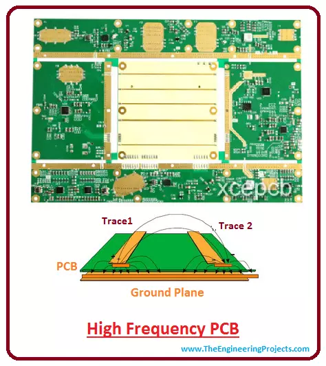
High Frequency PCB
- We are familiar with the word PCB, some of you who are not, it is an acronym of Printed Circuit Board which uses conductive tracks and paths to electronically connect different components on the board.
- Copper is used to provide conductive path on the board which is laminated on the substrate material which is mostly made up of epoxy resin.
- Signal communication plays a vital role in electronic projects specially when it comes to WiFi and satellite system.
- Where there is a need of signal communication between two objects, there is a need of high frequency boards.
- High Frequency PCB is a type of PCB used for signal transmission in the variety of applications including mobile, microwave, radio frequency and high speed design applications.
- High Frequency boards come with high frequency laminates are difficult to fabricate because they need to maintain thermal heat transfer of the application, in view of the sensitivity of the signal.
- Special materials are used to attain the high frequency given by the High Frequency PCB.
- Characteristics of the high frequency board can effect the overall performance of the signal, similarly any change in the Er value of the materials used can widely impact the impedance of the board.
- Most of the professionals prefer rogers dielectric material because it turns out to be less expensive, have low DK and DF value, reduced signal loss and appears to be suitable for fabrication and prototyping applications.
- Teflon is another common material used in the manufacturing process of the high frequency PCB, which comes with frequency of 5GHz.
- Some people are concerned about if FR4 can be used for RF applications? FR4 can be used in many applications requiring 1GHz to 10GHz frequency. But these FR4 based products come with their own drawbacks and limitations, they fail badly when high frequency is required for the signal transmission.
- In terms of DK, DF and water absorption factor, Teflon is the best, but more expensive than FR4.
- If your projects requires frequency more than 10GHz with higher quality and stable signal, then Teflon is the best choice.
- High frequency signals are vulnerable to noise and come with much tighter impedance tolerance as compared to conventional circuit boards.
- However, proper bend radius and accurate ground plans on impedance traces can help you design a product that can work in an effective way.
- By considering the certain parameters like coefficient of thermal expansion, dielectric constant, dissipation factor, temperature coefficient, thermal coefficient and quality of the material used can help the manufacturer design a final product that resonates with the client's needs and expectations.
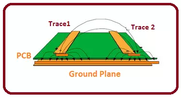
- Ground plane is an important part in high speed design applications, because it not only retains the quality of the signal but also helps in reducing EMI emissions. It works nicely by providing controlled impedance traces that resonate with load and electrical source. It plays an important role in keep the signal connected with their return path.
- If you are interested to make PCB design by yourself, you can choose any of these top 10 PCB designing software.
Prior Considerations
- The development of layout design is the most crucial part in making high speed products.
- If you are not expert in designing a layout design, you must have few words with the person who is going to make your layout design.
- Simple measures taken in the early stage can save you bunch of time in the later stage in case any remaking of the layout design is required.
- Give proper instructions and guidance to the layout designer so he can incorporate your idea in real time.
- Your instructions must include the sketch of the board, number of layers and signal layers on the board, thickness of the board, location of critical components on the board, location of bypassing components and the nature of critical traces, and the distance between the traces and the components, infact each and every thing you must keep in handy before you look for layout designer.
How to Pick a PCB Material
- Before you pick High Frequency PCB and suitable material for your project, you must take few things into considerations:
- Dielectric constant is the ability of material to store energy in the electric field. It is dependent on the direction of the material i.e. it will change as the axis of the material changes. It must be small enough so it delivers stable input in order to avoid any delay in the transmission signal.
- Similarly, Dissipation Factor must be small, because high DF can severely effect the quality of the transmission signal. So less DF will pertain to less signal wastage.
- Loss Tangent is another factor based on the moleculer structure of the material that can effect the RF material containing high frequencies. However, it is not of much concern for the low frequency signals.
- Proper spacing is very important in terms of cross talk and skineffect. Crosstalk happens when board starts interacting with itself and pertains to undesired coupling with their own components. In order to avoid crosstalk, distance between trace and plane must be minimum.
- Skineffect is directly connected with the resistance of the traces. It starts increasing when resistance increases which ultimately results in warming the board.So trace width and length must be selected in a way that it can not effect the board at higher frequencies.
- Smaller diameter vias come with low conductance and are most suitable as frequency go higher.
- Higher the value of Peel off resistance, impact endurance, and heat resistance, the better the quality of the signal.
- Coefficient of thermal expansion defines the effect of temperature on the size of the material. It widely effects on the drilling and assembly process of the PCB, because slight change in temperature can severely alter the size of the material. The thermal expansion of the copper foil must be same, because difference in thermal expansion may result in the separation of copper foil, in case material is subjected to changing temperature.
- Environment is a big concern in which your device is operating. If your device is going to be used in Lab or indoor environment then moisture won't be a big issue. Problem arises when your device exposes in wet environment. So, water absorption of the material should be low, because high absorption factor may alter the DF and DK value in the moisture.
- Rogers 4350B HF
- Rogers RO3001
- Rogers RO3003
- Taconic RF-35 Ceramic
- Taconic TLX
- ISOLA IS620 E-fibre glass
- ARLON 85N
How to Create Controlled Impedance Transmission Lines
- Development of controlled impedance transmission lines is very important in order to avoid any signal loss.
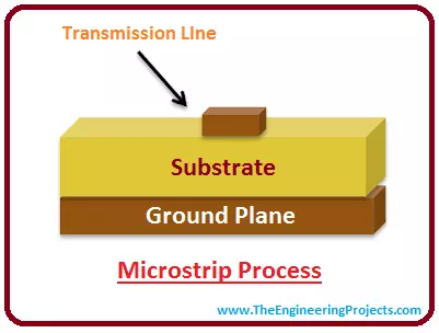
- There are two common ways to make controlled impedance transmission lines named as Microstrip and Stripline methods.
- Microstrip is the existence of the trace on the top layer that comes with a ground plane below.
- Calculating the impedance of a mircostrip is little bit tricky and complex though and depends on various factors including relative permitivity of the board material, thickness and width of the trace and its height above the plane. In order to achieve better result, ground plane must be closer to the top layer.
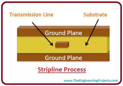
- Stripline is another addition to control impedance which is quite identical to microstirp with one exception i.e.it comes with an extra group plane on the top of the trace.
- In this case, trace must be placed between the layers of two planes.
- Stripline is better as compared to microstrip because it has an ability to contain EMI radiation within the two planes.
Applications
- High Frequency Products can be observed in number of applications including advanced communications systems, and industrial and medical applications.
- Similarly cell phones, GPS receiver, RF remote control, ZigBee make use of high speed products for better signal transmission.
- High speed test equipments are comprised of high speed products that provide better performance throughout the life span of the application.
- Airborne and Ground based radar systems are a true example of high speed circuits.
×
![]()


