


RF Communication with nRF24L01 and Raspberry Pi 4


Introduction
We're glad you could join us for another lesson in our series on programming for the Raspberry Pi 4. The previous chapter covered how to interface the USB barcode scanner with raspberry pi 4. We looked at different types of barcodes and what each stripe represents as well as the different types of barcode scanners available today. We also built a python program for the intelligent shopping cart and now our familiarity with barcodes and scanners and how they function has significantly increased. The benefits and drawbacks of its use were also discussed, but what we're interested in for this article is the transmission of radio frequency signals using the nrf24l01 Module in a raspberry pi 4.
Components
nRF24L01 RF module
Raspberry pi 4
Arduino Uno
Jumper wires
Power supply
16x2 liquid crystal display
Wireless communication systems, such as ESPS266 WiFi modules, are widely used in the design process. Further, the media chosen is determined by the function it will serve. It's no secret that the nRF24L01 is a widely used wireless channel for local area network communication. These modules have a band rate of 250Kbps to 2Mbps and transmit on the 2.4GHz (ISM band), which is permitted in many states and suitable for usage in industrial and healthcare settings. There is also the claim that these modules can communicate at a distance of up to 100 meters with the correct antennae.
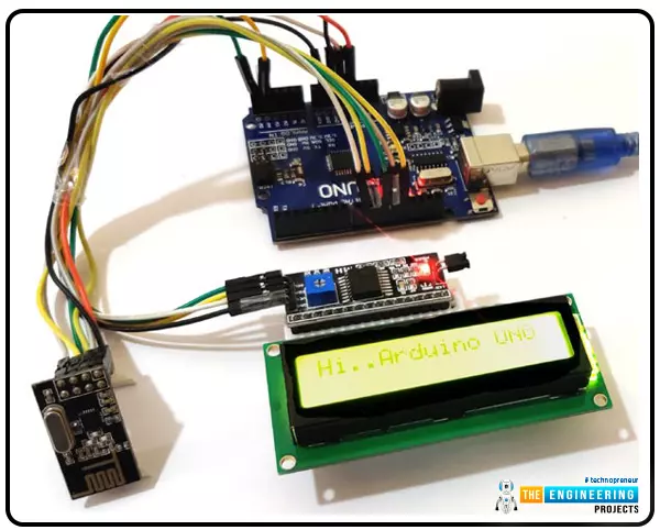
This tutorial demonstrates how to set up wireless communication between an Arduino UNO and a Raspberry Pi by utilizing the nRF24L01 - 2.4GHz RF Transceiver module. Raspberry Pi will broadcast data via nRF24L01, and Arduino Board will receive the data and display it on a 16x2 LCD. In addition to its built-in WiFi and Bluetooth Low Energy (BLE) capabilities, the nRF24L01 is also capable of wireless communication via BLE.
Both parts of the tutorial are equally important. In the first, we'll see how to connect the nRF24L01 to an Arduino so that it can function as a receiver, and in the second, we'll do the same thing with a Raspberry Pi can send out signals.
The meaning of "wireless radio frequency."
There are many different types of electromagnetic waves. Still, the ones utilized for radar signals and communications fall into roughly 3 kHz to 300 GHz range, known as "radio frequencies."
The term "radio frequency" is more commonly used to refer to electrical than mechanical oscillations. There are, however, examples of mechanical RF systems. Although radio frequency (RF) refers to an oscillation rate, the term "radio frequency" (RF) is sometimes used interchangeably with "radio" to describe the practice of communicating without the need for wires.
Numerous wireless technologies rely on RF fields, including cordless and cell phones, radio and television broadcasting stations, satellite telecommunication networks, Bluetooth communication modules and WiFi, and two-way radios.
External communications include various products like garage doors and microwave ovens, which use radio frequencies. The infrared frequencies of various wireless devices, like TV remote controllers, computer mice, and some wireless computer keyboards, have shorter electromagnetic wavelengths.
So, How Exactly Does Radio Frequency Operate?
The frequency of radio transmission is expressed in hertz (Hz) units, which stand for the count of cycles per second. Radio waves can travel from one thousand hertz (kHz) to several gigahertz (GHz). Microwaves, a form of radio wave, operate at much higher frequencies. Because of this, we can't see radio frequencies (RFs).
The wavelength' of a radio wave is proportional to the square root of the frequency 'f.' The relationship between frequency and wavelength can be expressed in megahertz and meters, respectively.
s = 300/f
At higher frequencies, electromagnetic radiation is manifested as infrared (IR), ultraviolet (UV), visible (Visible), X-ray (XR), and gamma-ray (GJ).
Traits of Radio Frequency
The following are some of the defining features of RF:
Low energy consumption
It has an excellent operational range (three to thirty meters), a data rate of up to two megabits per second, the ability to pass through walls, and can transmit in any direction.
The nRF24L01 Radio Frequency (RF) Module
Due to their half-duplex design, the nRF24L01 modules can only send or receive data but not do both. The Module's data transmission and reception are handled by the generic Nordic semi-conductor nRF24L01 IC. The IC uses the simple serial peripheral interface (SPI) protocol for communication, making it compatible with virtually all microcontrollers. Arduino makes things much simpler because there are numerous library resources available. The following table depicts the pin configurations of a typical nRF24L01 module.
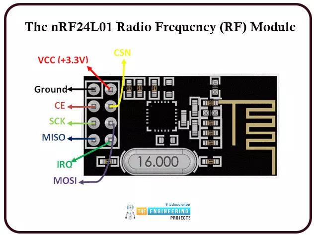
The Module is battery efficient, as its operating voltage ranges from 1.9V to 3.6V, and it draws minimal current (only 12mA) during regular operation. Most pins can be connected directly with 5V chipsets like Arduino, even though the voltage rating is 3.3V. Each Module also includes 6 Pipelines, which is a huge time saver. Simply put, each Module can exchange information with up to six others. Therefore, the Module can be used for IoT applications requiring the creation of star or mesh networks. With an extensive network address of 125 unique IDs, we may use 125 such components in a contained space without worrying about them interfering with one another.
Mechanics of Operation
Given that the Module supports 125 separate channels, creating a network containing 125 fully available modems at a single location is theoretically possible. Each device can simultaneously interface with up to six others on the same channel.
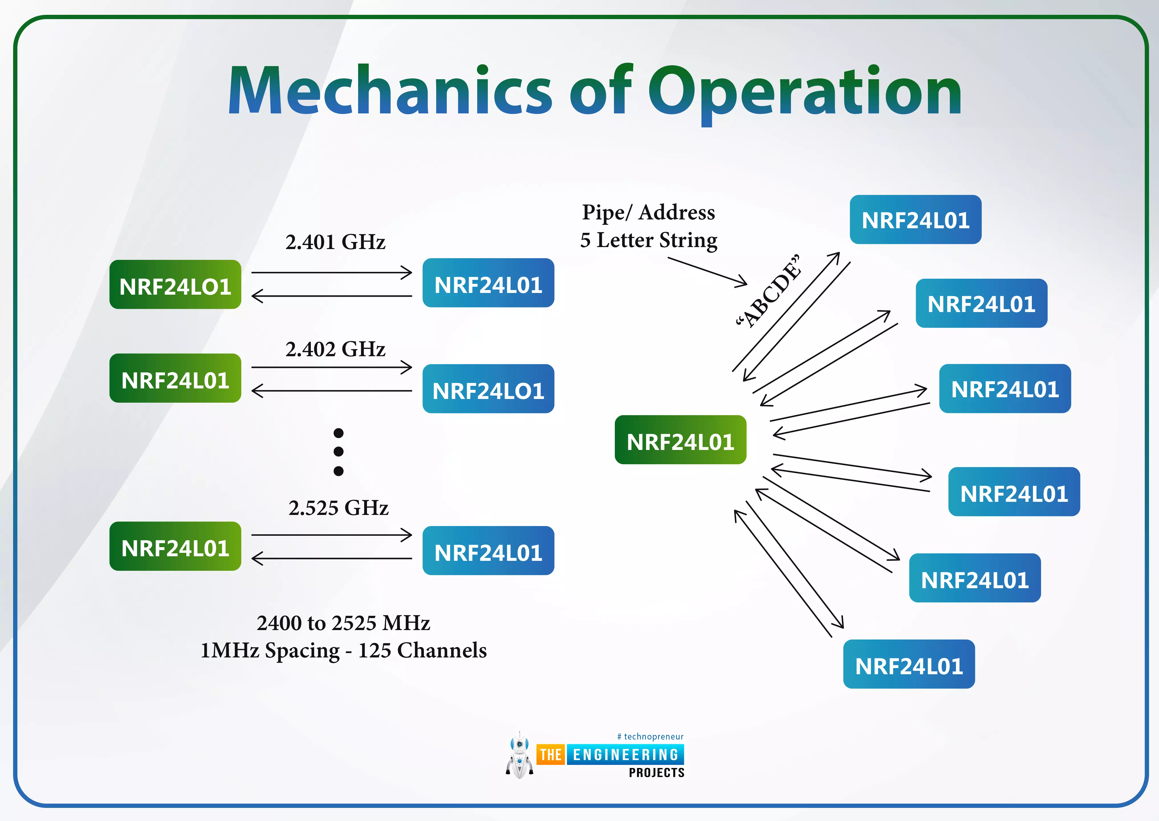
Transmission with this Module only uses about 12mA of power, less than a single display LED screen. The Module requires a voltage of 1.9V to 3.6V to function. Still, the other pins are 5V logic compatible, allowing us to connect it directly to an Arduino without needing logic-level converters.
Three of these terminals are used for SPI communication and must be hooked up to the SPI pins on the Arduino; however, the SPI pins on different Arduino boards are labelled differently. Connecting the CSN and CE pins to any input pin on the Arduino board toggles between standby and active modes and transmit and command modes for the Module. The last connector is an interrupt pin, which is optional.
Variations in Modules
The NRF24L01 modules can be found in a wide range of versions. The model with a built-in antenna is the clear frontrunner. This reduces the transmission range of the Module to around 100 meters but allows for a smaller module size.
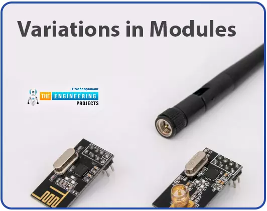
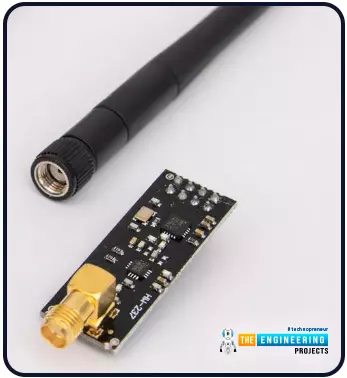
In the second variant, an SMA connector replaces the onboard antenna, allowing us to use a duck transmitter for enhanced signal strength.
The third variant displayed here also features the duck antenna with an RFX2401C microprocessor with an integrated Power Amplifier and Low-Noise Amplifier). This can increase the NRF24L01's transmission range in open areas by 1000.
Circuit Schematic
Integrating nRF24L01 with Arduino
The components in the circuit design for linking nRF24L01 to Arduino are few, and the process is straightforward. SPI will be used to link the nRF24l01, and I2C will connect the 16x2 LCD.

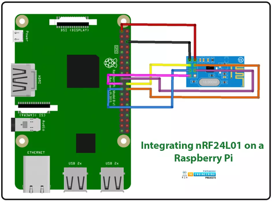
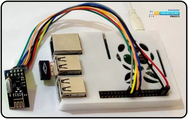
Integrating nRF24L01 on a Raspberry Pi
Because only the SPI adapter is required to link the Raspberry Pi and the nRF24L01, the corresponding circuit schematic is pretty straightforward.
How to Use nRF24l01 with Raspberry Pi to Communicate
Python3 will be used for Raspberry Pi's programming. The Arduino platform is not the only one that can use C/C++. However, if you're programming in Python, you can get a library for nRF24l01 that's already been made. Keep in mind that the library and the python program must be in the same folder for the python program to use it. Create a folder to house your applications and library files after you have downloaded and extracted the library. After the necessary libraries have been installed, you can begin coding immediately. Importing libraries like the GPIO library for communicating with the Raspberry Pi's GPIO pins and the time library for using the Pi's clock and date functions are the first steps in writing any program.
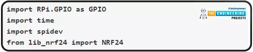
import RPi.GPIO as GPIO
import time
import spidev
from lib_nrf24 import NRF24
It would be best if you switched to the "Broadcom SOC channel" for the GPIO setting. Pins are referred to by their "Broadcom SOC channel" numbers, which follow the letters "GPIO" (GPIO01, GPIO02, etc.). The Board Numbers are not these.

GPIO.setmode(GPIO.BCM)
After that, we'll assign a permanent address for the pipe. To send data to Arduino, you'll need to use this address. There will be a hexadecimal representation of the address.
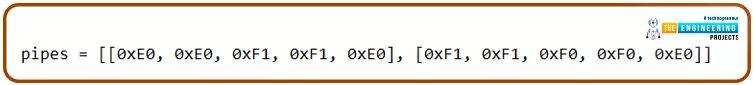
pipes = [[0xE0, 0xE0, 0xF1, 0xF1, 0xE0], [0xF1, 0xF1, 0xF0, 0xF0, 0xE0]]
Start the radio with the CE pin (GPIO08) and the CSN pin (GPIO25).
radio.begin(0, 25)
Change the power levels to minimal, the channel address to 76, the data rate to 1 Mbps, and the payload size to 32 bits.
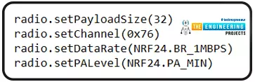
radio.setPayloadSize(32)
radio.setChannel(0x76)
radio.setDataRate(NRF24.BR_1MBPS)
radio.setPALevel(NRF24.PA_MIN)
Start the data writing process by opening the pipes and displaying some nRF24l01 basics.
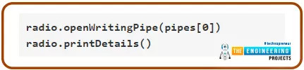
radio.openWritingPipe(pipes[0])
radio.printDetails()
Get your message ready to send as a string. Arduino UNO will receive this message.
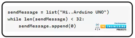
sendMessage = list("Hi..Arduino UNO")
while len(sendMessage) < 32:
sendMessage.append(0)
Send the string's first character to the stereo and continue doing so until the radio is ready to receive it. In addition, a debug statement detailing the time and date the message was delivered should be printed.
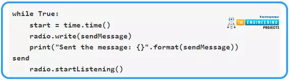
While True:
start = time.time()
radio.write(sendMessage)
print("Sent the message: {}".format(sendMessage))
send
radio.start listening()
A timed-out error message should be printed if the thread is finished and the conduit is closed.
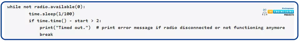
while not radio.available(0):
time.sleep(1/100)
If time.time() - start > 2:
print("Timed out.") # print error message if radio disconnected or not functioning anymore
break
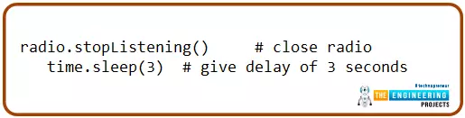
If you want to send another message, turn off the radio and disconnect from the connection for three seconds.
radio.stopListening() # close radio
time.sleep(3) # give a delay of 3 seconds
If you know the fundamentals of Python, you can easily comprehend the Raspberry program. You will find a fully functional Python program at the end of this tutorial.
Putting the Python Code for the Raspberry Pi to Work
If you follow the steps below, running the software will be a breeze.
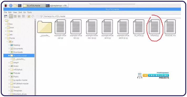
You should keep the Python source code and library files together.
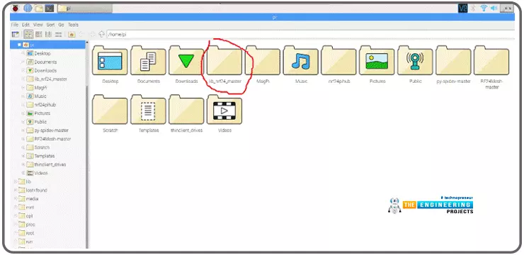
My Sender program file is nrfsend.py, and all the related files are in the same directory.
Access Raspberry Pi's command prompt. Use the cd command to get to the directory containing the python script.
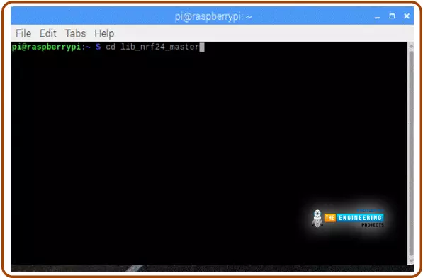
Navigate to the directory, type "sudo python3 your program.py," and hit enter to run the program. In less than a minute, you'll likely see nRf24's essentials laid out, and the broadcaster will begin broadcasting its bulletins at three-second intervals. Once the send is complete, the debug message will appear.
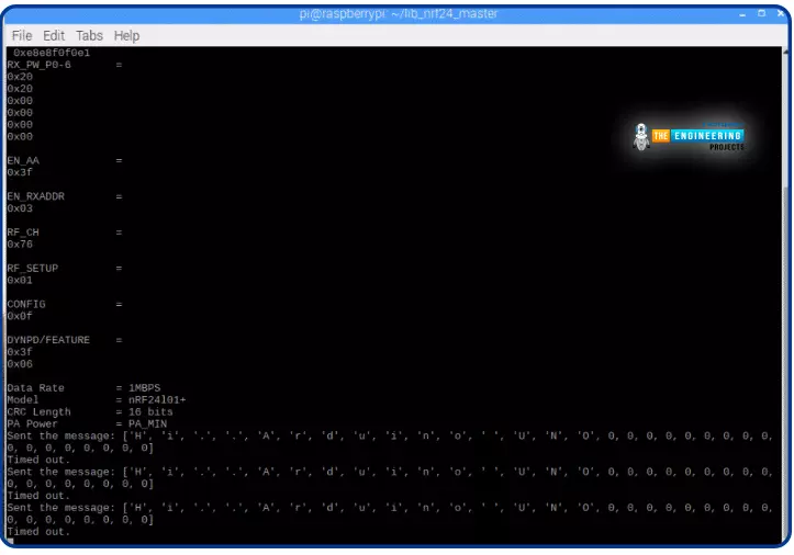
The Arduino UNO will now display the same code as the receiver.
The nRF24l01 and Arduino UNO: Message Reception Programming
The Arduino UNO can be programmed in a manner not dissimilar to that of the Raspberry Pi. Our procedures will be very similar; however, we'll use a different language for programming and other processes. The procedure will incorporate the nRF24l01 readout. Download the nRF24l01 Arduino library from GitHub. To get started, make sure all required libraries are installed. We're using a 16x2 I2C LCD, so we need to include the Wire.h library; the nRF24l01 communicates via SPI, so we also need the SPI library.

#include<SPI.h>
#include <Wire.h>
Don't forget to add the RF24 and LCD libraries so you may use them.

#include<RF24.h>
#include <LiquidCrystal_I2C.h>
Put the LCD's I2C address—27 in this case, as it's a 16x2 display—into the appropriate function.

LiquidCrystal_I2C lcd(0x27, 16, 2);
Pin 9 serves as the RF24's Common Emitter, and pin 10 serves as its Common Source Negative.
RF24 radio(9, 10) ;
Turn the radio on and tune in to channel 76. In addition, open the pipe for reading by setting the address to that of the Raspberry Pi.
radio.begin();
radio.setPALevel(RF24_PA_MAX) ;
radio.setChannel(0x76) ;
const uint64_t pipe = 0xE0E0F1F1E0LL ;
radio.openReadingPipe(1, pipe) ;
Start the I2C data transfer and initialize the LCD screen.
Wire.begin();
lcd.begin();
lcd.home();
lcd.print("Ready to Receive");
Turn on the radio's receiver and enter a message length of 32.
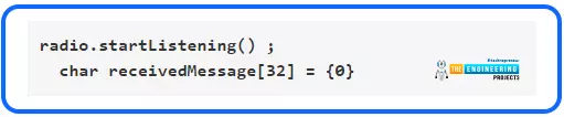
radio.startListening() ;
char receivedMessage[32] = {0}
The message will be read and saved immediately if a radio is connected. Display the message on the screen and send it to the serial monitor till the following message is received. Put the radio on hold while you tune in, then try again later. Right this way, in ten microseconds.
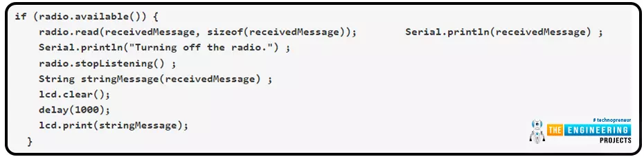
if (radio.available()) {
radio.read(receivedMessage, sizeof(receivedMessage));
Serial.println(receivedMessage) ;
Serial.println("Turning off the radio.") ;
radio.stopListening() ;
String stringMessage(receivedMessage) ;
lcd.clear();
delay(1000);
lcd.print(stringMessage);
}
Copy and paste the code below into your server and allow time for the response to arrive.
NRF Transmitter Side Code (Raspberry Pi)
import RPi.GPIO as GPIO # import gpio
import time #import time library
import spidev
from lib_nrf24 import NRF24 #import NRF24 library
GPIO.setmode(GPIO.BCM) # set the gpio mode
# set the pipe address. This address should be entered on the receiver to
pipes = [[0xE0, 0xE0, 0xF1, 0xF1, 0xE0], [0xF1, 0xF1, 0xF0, 0xF0, 0xE0]]
radio = NRF24(GPIO, spidev.SpiDev()) # use the gpio pins
radio.begin(0, 25) # start the radio and set the ce,csn pin ce= GPIO08, csn= GPIO25
radio.setPayloadSize(32) #set the payload size as 32 bytes
radio.setChannel(0x76) # set the channel as 76 hex
radio.setDataRate(NRF24.BR_1MBPS) # set radio data rate
radio.setPALevel(NRF24.PA_MIN) # set PA level
radio.setAutoAck(True) # set acknowledgement as true
radio.enableDynamicPayloads()
radio.enableAckPayload()
radio.openWritingPipe(pipes[0]) # open the defined pipe for writing
radio.printDetails() # print basic detals of radio
sendMessage = list("Hi..Arduino UNO") #the message to be sent
while len(sendMessage) < 32:
sendMessage.append(0)
While True:
start = time.time() #start the time for checking delivery time
radio.write(sendMessage) # just write the message to radio
print("Sent the message: {}".format(sendMessage)) # print a message after succesfull send
radio.startListening() # Start listening the radio
while not radio.available(0):
time.sleep(1/100)
if time.time() - start > 2:
print("Timed out.") # print error message if the radio disconnected or not functioning anymore
break
radio.stopListening() # close radio
time.sleep(3) # give delay of 3 seconds
NRF Receiver Side Code (Arduino):
#include<SPI.h> // spi library for connecting nrf
#include <Wire.h> // i2c libary fro 16x2 lcd display
#include<RF24.h> // nrf library
#include <LiquidCrystal_I2C.h> // 16x2 lcd display library
LiquidCrystal_I2C lcd(0x27, 16, 2); // i2c address is 0x27
RF24 radio(9, 10) ; // ce, csn pins
void setup(void) {
while (!Serial) ;
Serial.begin(9600) ; // start serial monitor baud rate
Serial.println("Starting.. Setting Up.. Radio on..") ; // debug message
radio.begin(); // start radio at ce csn pin 9 and 10
radio.setPALevel(RF24_PA_MAX) ; // set power level
radio.setChannel(0x76) ; // set chanel at 76
const uint64_t pipe = 0xE0E0F1F1E0LL ; // pipe address same as sender i.e. raspberry pi
radio.openReadingPipe(1, pipe) ; // start reading pipe
radio.enableDynamicPayloads() ;
radio.powerUp() ;
Wire.begin(); //start i2c address
lcd.begin(); // start lcd
lcd.home();
lcd.print("Ready to Receive"); // print starting message on lcd
delay(2000);
lcd.clear();
}
void loop(void) {
radio.startListening() ; // start listening forever
char receivedMessage[32] = {0} ; // set incmng message for 32 bytes
if (radio.available()) { // check if message is coming
radio.read(receivedMessage, sizeof(receivedMessage)); // read the message and save
Serial.println(receivedMessage) ; // print message on serial monitor
Serial.println("Turning off the radio.") ; // print message on serial monitor
radio.stopListening() ; // stop listening radio
String stringMessage(receivedMessage) ; // change char to string
lcd.clear(); // clear screen for new message
delay(1000); // delay of 1 second
lcd.print(stringMessage); // print received mesage
}
delay(10);
}
Features That Have the Most Impact on RF Module Efficiency
The RF module's performance will be affected by the same factors as any other RF component. For instance, a transmitter's output power can be increased to extend the range of a transmission. However, this will cause a greater consumption of electricity by the transmitters (TX) device, reducing the useful life of battery-operated gadgets. Increasing the system's transmit power also makes it more vulnerable to interference from a second RF source.
Similarly, boosting the receiver's sensitivity increases the usable communication range but increases the risk of an error brought on by interference from other RF equipment. Matching antennas on both ends of a communication link can potentially boost the overall system's performance.
Finally, the regarded remote distance of any given system is typically measured in an open-air line-of-sight outline without any interference; nevertheless, problems such as floors, walls, and dense structures will frequently grasp the radio wave signals; thus, the actual operational distance will typically be less than specified.
Uses for Radio Frequency Communication
The most common uses of radio frequency communication are in the areas of wireless data and voice transfer, home automation, and remote control, as well as in the industrial and commercial sectors.
RF-controlled switches can be used in home automation applications as an alternative to traditional switches. An RF remote allows one to operate lights and other electronics without leaving their current location. Those with mobility issues will benefit the most from this app. RF communication is helpful in industrial settings for directing autonomous robots and motorized vehicles. These robot vehicles are often employed in hazardous tasks humans cannot undertake. A data transmission unit is required to direct the motion of the robotic vehicles.
Multiple factors make radio frequency (RF) transmission preferable to infrared (IR) (infrared). The more extended range of RF signals makes them ideal for long-distance communications. Unlike radio frequency (RF), which can go across obstacles, infrared (IR) generally requires a clear path from transmitter to receiver. The reliability of RF transmission is far greater than that of infrared remote communications. While radio frequency (RF) communications require other IR-emitting devices that can disrupt a precise frequency range, infrared (IR) communications.
Problems with Radio Frequency
These are some of RF's drawbacks.
Preschoolers, expectant mothers, the elderly, those with pacemakers, little birds, flora, wildlife, insects, etc., are all negatively impacted by unregulated RF radiation.
More lightning has been seen in nearby cellular towers that use radio frequency than in other areas.
Some fruit crops in the vicinity of RF towers are also negatively impacted.
Because RF waves are accessible in both line-of-sight (LOS) and non-LOS zones of the transmitter, hackers can easily break into the system and decode sensitive personal or government data.
This problem can be avoided by employing highly protected methods like AES, WEP, WPA, etc., while transmitting data over radio frequency waves. Spread spectrum and frequency hopping modulation methods can also be applied to RF signals to prevent such eavesdropping.
Conclusion
This concludes the comprehensive instruction on wireless communication between a Raspberry Pi and an Arduino UNO via nRf24l01 modules. The 16 * 2 liquid crystal display will show the message. Pipe addresses are crucial on the Arduino UNO and the Raspberry Pi 4. In the following tutorial, we will learn how to Call and Text using Raspberry Pi and GSM Module in pi 4.


