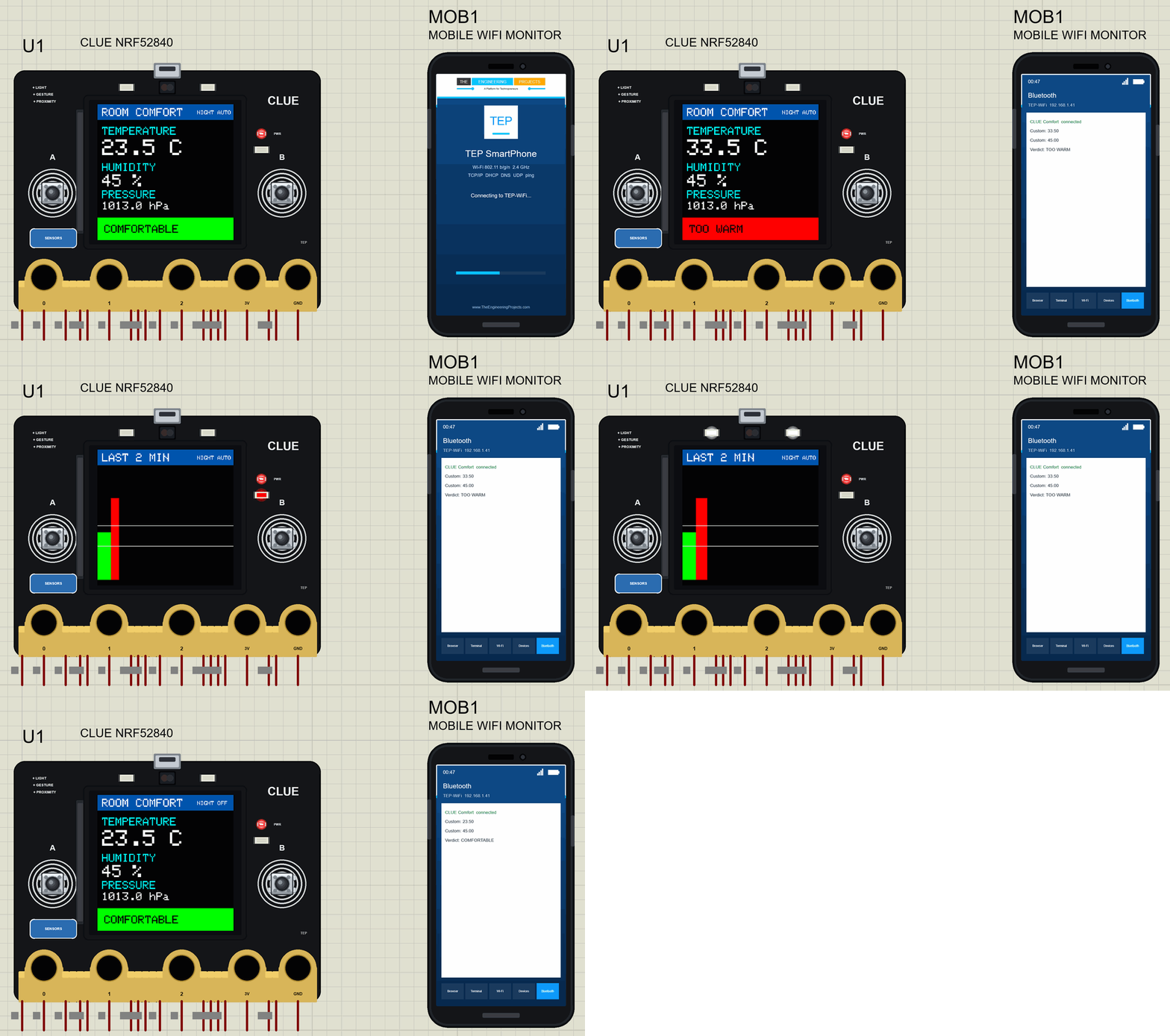
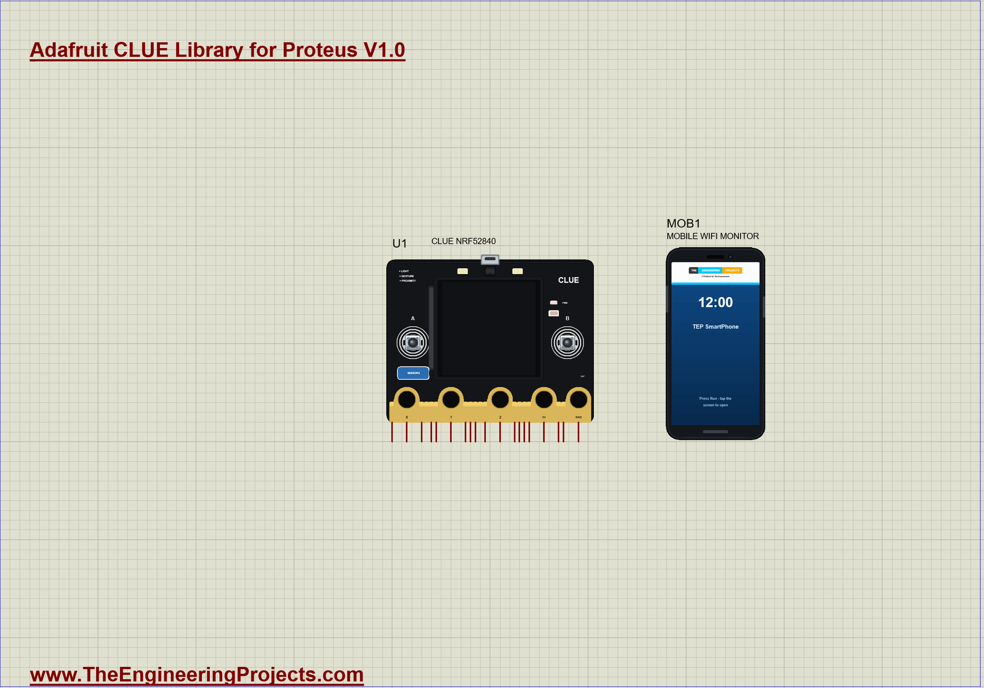
Hello friends, I hope you all are doing great. Today, I am going to share the Adafruit CLUE Library for Proteus, so you can run a display and Bluetooth LE simulation of Adafruit's CLUE. The CLUE has the shape of a micro:bit with a colour screen in the middle: a 1.3" 240 x 240 display, two buttons, a set of sensors and an nRF52840 with Bluetooth LE. Our part is drawn at its real size, and it runs your Arduino sketch in Proteus 8.5 - whatever Adafruit_GFX draws appears on its screen.
Adafruit CLUE Library for Proteus
Latest version: V1.0 (November 2026, this tutorial)
Other new Arduino boards: UNO R4 WiFi · Nano ESP32 · UNO WiFi Rev2 · Nano 33 IoT · UNO Q · UNO R4 Minima · Nano Every · MKR WiFi 1010 · Nano RP2040 Connect · STM32 Black Pill · Nucleo-F401RE · STM32 Blue Pill · Teensy 4.1 · Arduino Due · Arduino Leonardo · Arduino Micro · BBC micro:bit V2 · GIGA R1 WiFi · MKR WAN 1310 · Nano 33 BLE Sense · XIAO nRF52840 Sense · RAK4631 WisBlock · Nano Matter · nRF52840 DK · nRF5340 DK · nRF9151 DK · nRF7002 DK · Nordic Thingy:53 · xG24 Dev Kit · xG24 Explorer Kit · Thunderboard BG22 · SiWx917 Dev Kit · B-L475E-IOT01A · NUCLEO-WB55RG · NUCLEO-WL55JC1 · NUCLEO-H743ZI2 · SAM R21 Xplained Pro · FRDM-MCXN947 · Portenta H7 · LP-CC2652R7 · PSoC 6 WiFi-BT · Feather nRF52840 · Thingy:91 X · xG26 Dev Kit · nRF52 DK · nRF52833 DK · nRF52840 Dongle · nRF5340 Audio DK · nRF54H20 DK · nRF54LM20 DK · nRF9160 DK · nRF9161 DK · nRF21540 DK · Thingy:52 · Thingy:91 · ItsyBitsy nRF52840 · SparkFun Pro nRF52840 Mini
RF modules: nRF24L01 · nRF24L01 PA LNA · CC1101 · RFM69HCW · HC-12 · 433MHz RF · XBee
Temperature and weather sensors: DHT11 / DHT22 · DS18B20 · BME280 · BMP280 · SHT31 · AHT20 · BME680 · MLX90614 · MAX6675
Helping Tools
- Laptop WiFi Monitor: a laptop on the Wi-Fi of your design: a browser, a TCP / UDP terminal and ping
- Mobile WiFi Monitor: a smartphone that opens the pages of your board and sends it commands
- Serial Monitor Advance: a serial terminal window for the UART of your board
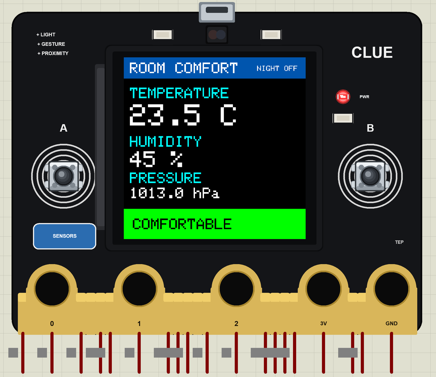
For the demo we built a Bluetooth room comfort display: the CLUE shows the temperature, the humidity and the pressure with a coloured verdict, draws a 2-minute graph, turns its white LEDs into a night light and sends everything to a phone.
NOTICE: Proteus has no nRF52840 model, so our team has put a lot of effort into building this board ourselves: the screen, the pins, the buttons, the LEDs, the sensors and Bluetooth LE to the phone are all our own model, and your sketch compiles with our free TEP Boards for Proteus add-on. Your feedback is the fuel that keeps us going, so please tell us what you think in the comments below. And if our free libraries help you, you can buy us a coffee. So, let's get started with the Adafruit CLUE Library for Proteus:
What is the Adafruit CLUE?
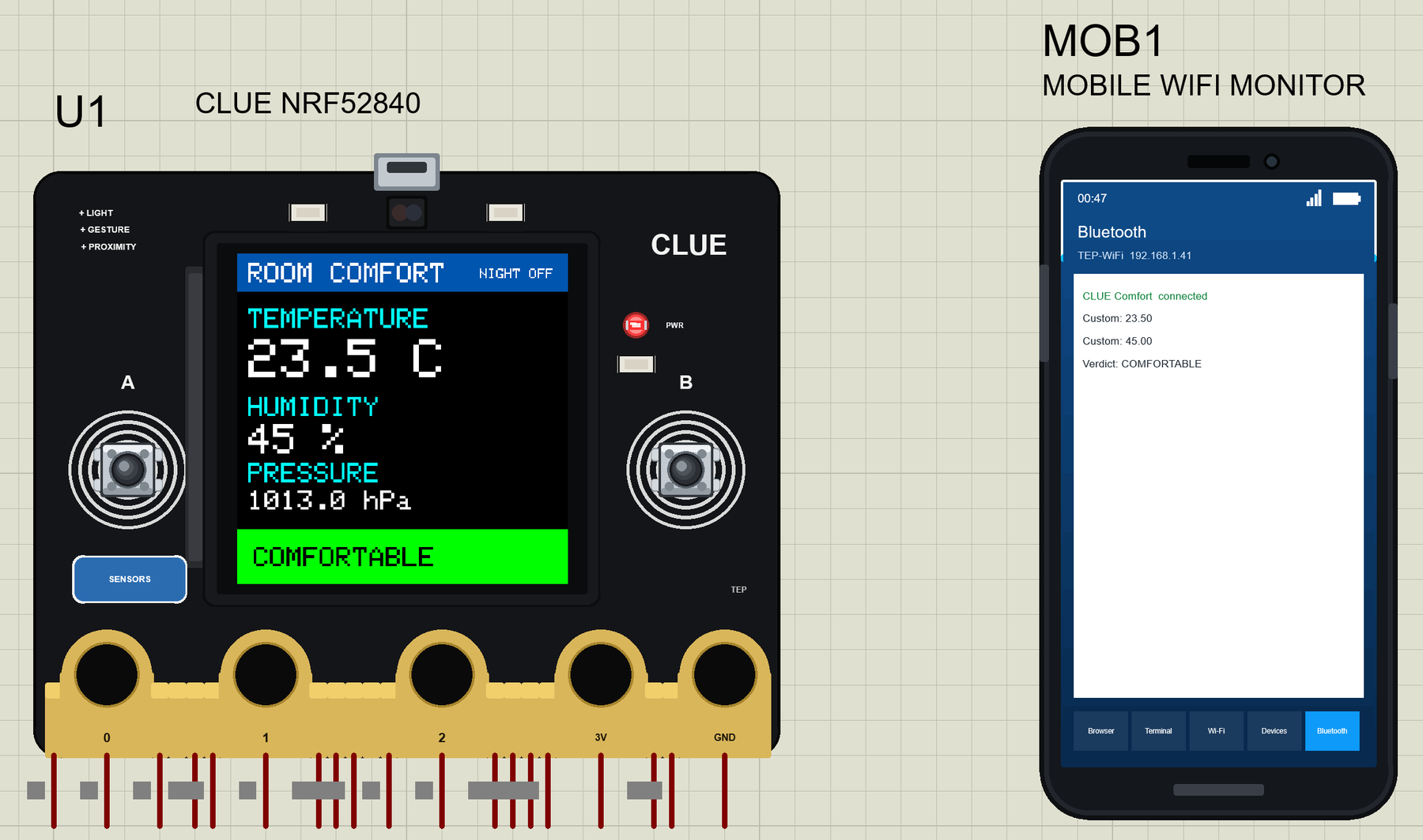
The CLUE (Adafruit product 4500) is a development board with the outline and the edge connector of the BBC micro:bit, so it fits micro:bit cases, robots and breakout boards. Instead of the LED matrix it has a 1.3" 240 x 240 IPS display, and under it sits Nordic's nRF52840: an Arm Cortex-M4F at 64 MHz with 1 MB of flash, 256 KB of RAM, native USB and Bluetooth LE. Around them Adafruit packed a sensor lab: motion, a magnetometer, light, colour, gesture and proximity, humidity, temperature and pressure, and a microphone.
| Part | The real CLUE | In the library |
|---|---|---|
| Processor | nRF52840, Bluetooth LE | your Arduino sketch, ArduinoBLE |
| Display | 1.3" 240 x 240 IPS (ST7789) | Adafruit_ST7789 + Adafruit_GFX, on the part |
| Buttons | A (D5) and B (D11) | both clickable, LOW when pressed |
| LEDs | two bright white (D43), red (D17), a NeoPixel | white and red lit when HIGH |
| Sensors | IMU, magnetometer, APDS9960, humidity, pressure, mic | the Sensors window |
| Edge connector | micro:bit style: rings 0, 1, 2, 3V, GND + fingers | the same pins |
| Size | the micro:bit outline, about 52 x 42 mm | drawn at real size |
The micro:bit Edge Connector
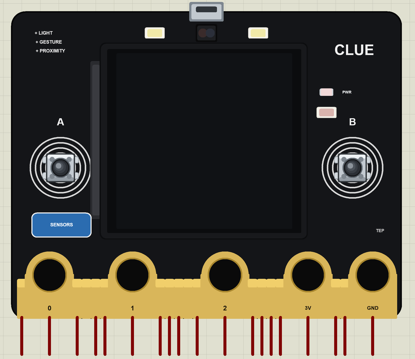
Along the bottom edge the CLUE has the same gold connector as the micro:bit: five big rings - 0, 1, 2, 3V and GND - for crocodile clips, and small fingers for the other pins. Pin numbers match: P0 is D0, P19 and P20 are the I2C pins, P5 and P11 are buttons A and B. Our part draws the connector exactly like our BBC micro:bit V2 Library for Proteus, so the same accessories fit.
A Screen Where the Matrix Was
The display is the CLUE's main feature. It is driven by an ST7789 controller over SPI, and Adafruit's libraries make it easy: tft.init(240, 240) starts it, and the usual Adafruit_GFX calls draw text, lines, rectangles and bitmaps. Our part models the controller itself, so the same sketch code draws the same picture in the simulation.
Features of the Adafruit CLUE Library for Proteus
- The CLUE at real size: the black board, the 240 x 240 display, buttons A and B on their fingerprint swirls, the light sensor between the two white LEDs, the micro-USB, the CLUE logo and the edge connector, with our small TEP signature.
- A real screen: Adafruit_ST7789 and Adafruit_GFX draw on the part while the simulation runs.
- Your sketch: a .hex for "Adafruit CLUE (TEP Proteus)" with Adafruit's pin numbers.
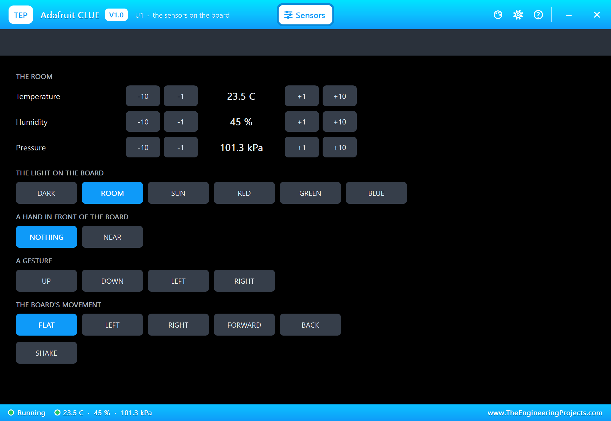
- The sensors: temperature, humidity, pressure, light, colour and motion through the board package's sensor libraries, set from the Sensors window.
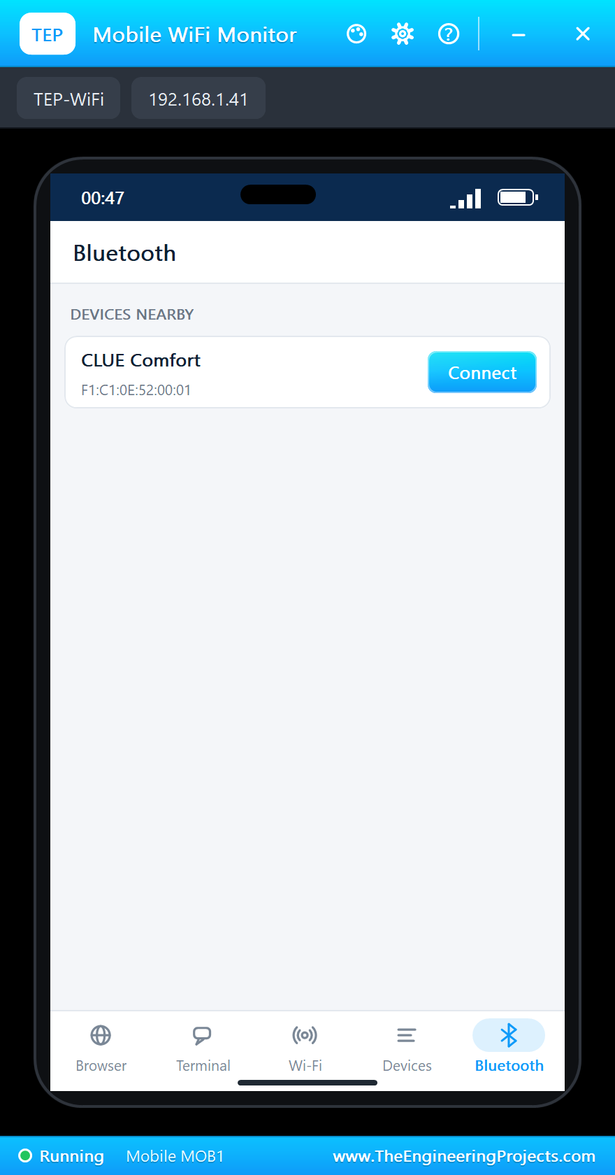
- Bluetooth LE: ArduinoBLE with services, characteristics, descriptors and notifications; our Mobile WiFi Monitor is the phone.
- A complete package: about 3.4 MB with the part, the add-on, the phone and the demo, without the source code of the models.
The CLUE in Proteus Simulation
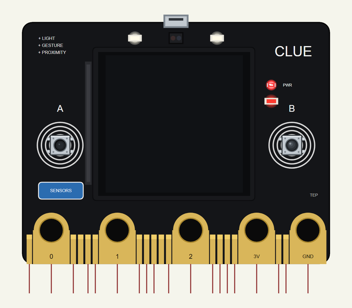
Search CLUE in Pick Devices; the device CLUE NRF52840 is in TEPCLUE.LIB (Microprocessor ICs, Bluetooth Boards), with the prefix U. The micro-USB opens the serial monitor, the blue SENSORS pad the Sensors window.
The Pins
| Pins | What the library does with them |
|---|---|
| 0, 1, 2 (rings) | analogRead 0 to 1023 for 0 to 3.3 V (A2, A3, A4), GPIO, PWM; 0 / 1 = Serial1 RX / TX |
| P3, P4, P10, P12, P16 | analogRead (A5, A6, A7, A0, A1), GPIO, PWM |
| P6 to P9, P13 to P15 | GPIO, PWM, interrupt, pulse timing |
| P19, P20 | Wire SCL / SDA |
| on the board | buttons A / B (D5 / D11), red LED D17, white LEDs D43, the display D29 to D34 |
Download Adafruit CLUE Library for Proteus
Click the button below to download Adafruit-CLUE-Library-for-Proteus-v1.0.zip (about 3.4 MB, without the source code of the models):
Adafruit CLUE Library for Proteus V1.0- README.txt: installation, the demo, the pins, the properties, troubleshooting and the limits.
- Proteus Library Files:
TEPCLUE.LIBand the phone and laptop. - Proteus Model Files:
TEPNET.DLL. - Arduino Code: the demo sketch and the TEP Boards for Proteus add-on 1.94.0, with ArduinoBLE and the sensor libraries.
- Proteus Simulation: the demo project, its HEX file and a copy of the DLL.
No Proteus yet? Read How to Download and Install Proteus 7 and 8. New to libraries? Follow How to Install a New Library in Proteus.
How to Install Adafruit CLUE Library for Proteus
- Close Proteus and extract the whole zip file, for example to your Desktop.
- Copy the files from Proteus Library Files into the LIBRARY folder of Proteus.
- Copy
TEPNET.DLLfrom Proteus Model Files into the MODELS folder, replacing an older copy. - Delete
TEPCLUE.IDXfrom the LIBRARY folder if it is there. - For your own sketches, copy Arduino Code\TEP Boards for Proteus\hardware into your Arduino sketchbook (Documents\Arduino), install Adafruit ST7735 and ST7789, Adafruit GFX and Adafruit BusIO from the Library Manager and restart the Arduino IDE; the board is Adafruit CLUE (TEP Proteus).
- Start Proteus, press P and search for CLUE.
Demo: a Room Comfort Display in Simulation
Most of us notice a stuffy or cold room only when we already feel bad. A small display on the desk that judges the room - and a phone that can check it from the next room - is a nice first project for the CLUE, because it uses the screen, the sensors, the buttons, the LEDs and Bluetooth together.
Open CLUE-BLE-Comfort-Display.pdsprj. U1 runs CLUE_Comfort_Display.hex with the room at 23.5 C, 45 % and 101.3 kPa (its TEMPERATURE, HUMIDITY and PRESSURE properties); MOB1 is the phone. Everything else is on the CLUE itself, so there are no wires.
| What | Meaning |
|---|---|
| COMFORTABLE (green) | 20 to 26 C and 30 to 60 % |
| TOO WARM / TOO COLD | above 26 C (red) / below 20 C (blue) |
| TOO DRY / TOO DAMP | below 30 % / above 60 % (orange) |
| button A | the readings / the graph of the last 2 minutes |
| button B | the night light AUTO / OFF |
| the white LEDs | the night light: lit while the room is dark (AUTO) |
| the red LED | blinks while the room is not comfortable |
The Bluetooth Service
The sketch uses the standard Environmental Sensing service, 0x181A, with the standard temperature (0x2A6E) and humidity (0x2A6F) characteristics, plus a text characteristic for the verdict with a readable 0x2901 name:
BLEService comfortService("181A");                          // Environmental Sensing
BLEFloatCharacteristic tempChar("2A6E", BLERead | BLENotify);
BLEFloatCharacteristic humidChar("2A6F", BLERead | BLENotify);
BLEStringCharacteristic verdictChar("19B100C1-E8F2-537E-4F6C-D104768A1214", BLERead | BLENotify, 12);
BLEDescriptor verdictLabel("2901", "Verdict");
The Verdict
judge() checks the temperature first and then the humidity, so a hot and humid room is called TOO WARM - the more urgent problem:
const char *judge() {                                       // the verdict: the temperature first, then the humidity
  if (tempC > WARM_C) return "TOO WARM";
  if (tempC < COLD_C) return "TOO COLD";
  if (humidity < DRY_RH) return "TOO DRY";
  if (humidity > DAMP_RH) return "TOO DAMP";
  return "COMFORTABLE";
}
Drawing Without Flicker
Clearing the whole screen every second would make it flicker. drawReadings() prints each value with a background colour - setTextColor(white, black) - so the new digits simply cover the old ones, and the verdict box is filled again only when the verdict changes:
void drawReadings() {                                       // the values (drawn over their own background: no flicker)
  tft.setTextColor(ST77XX_WHITE, ST77XX_BLACK);
  tft.setTextSize(4); tft.setCursor(8, 62); tft.print(tempC, 1); tft.print(F(" C "));
  tft.setTextSize(3); tft.setCursor(8, 124); tft.print(humidity, 0); tft.print(F(" %  "));
  tft.setTextSize(2); tft.setCursor(8, 172); tft.print(hpa, 1); tft.print(F(" hPa "));
  if (!boxDirty) return;                                    // the verdict box only when the verdict changed
  boxDirty = false;
  tft.fillRect(0, 200, 240, 40, colourOf(verdict));
  tft.setTextColor(ST77XX_BLACK); tft.setTextSize(2); tft.setCursor(12, 213); tft.print(verdict);
}
The Graph
Every second the temperature goes into a list of 120 values. drawGraph() draws one bar per second, two pixels wide and coloured by the temperature, with white lines at 20 and 26 C. Each column paints its own black above the bar instead of clearing the whole graph first, so the picture never goes blank:
void drawGraph() {                                          // a bar per second, 2 px wide, each column drawn over its own black
  const int base = 230;
  for (byte i = 0; i < HISTORY; i++) {
    const int h = i < used ? constrain((history[i] - 10) * 6, 0, 190) : 0;
    tft.fillRect(i * 2, 36, 2, base - h - 36, ST77XX_BLACK);
    if (h) tft.fillRect(i * 2, base - h, 2, h, history[i] > WARM_C ? ST77XX_RED : history[i] < COLD_C ? ST77XX_BLUE : ST77XX_GREEN);
  }
  tft.drawFastHLine(0, base - (int)((WARM_C - 10) * 6), 240, ST77XX_WHITE);   // the comfort band: 26 C and 20 C
  tft.drawFastHLine(0, base - (int)((COLD_C - 10) * 6), 240, ST77XX_WHITE);
}
The Night Light
The light sensor's clear channel tells how bright the room is. In AUTO mode the white LEDs light while it is below 20:
void nightLight() {                                         // AUTO: the white LEDs light while the room is dark
  const bool want = nightAuto && light < DARK;
  if (want == nightOn) return;
  nightOn = want;
  digitalWrite(PIN_LED2, nightOn ? HIGH : LOW);
  Serial.println(nightOn ? F(">> DARK: the night light ON") : F(">> the night light OFF"));
}
Reading the Buttons
Both buttons go through one small helper that accepts a press only when the level changed and stayed quiet for 30 ms:
bool pressed(byte pin, bool &last, unsigned long &since) {  // a debounced press: HIGH to LOW, then quiet for 30 ms
  const bool now = digitalRead(pin);
  if (now == last || millis() - since < DEBOUNCE_MS) return false;
  last = now; since = millis();
  return now == LOW;
}
Run the Simulation
Press Run. The display shows the room and the green COMFORTABLE box; the serial monitor - the same window as our TEP Serial Monitor Advance for Proteus - shows the name the board advertises and the first readings:
Adafruit CLUE Bluetooth Room Comfort Display - The Engineering Projects
Advertising as "CLUE Comfort"   A = the next page, B = the night light AUTO / OFF
>> COMFORTABLE: 23.5 C, 45 %
Room: 23.5 C, 45 %, 1013.0 hPa, light 270, COMFORTABLE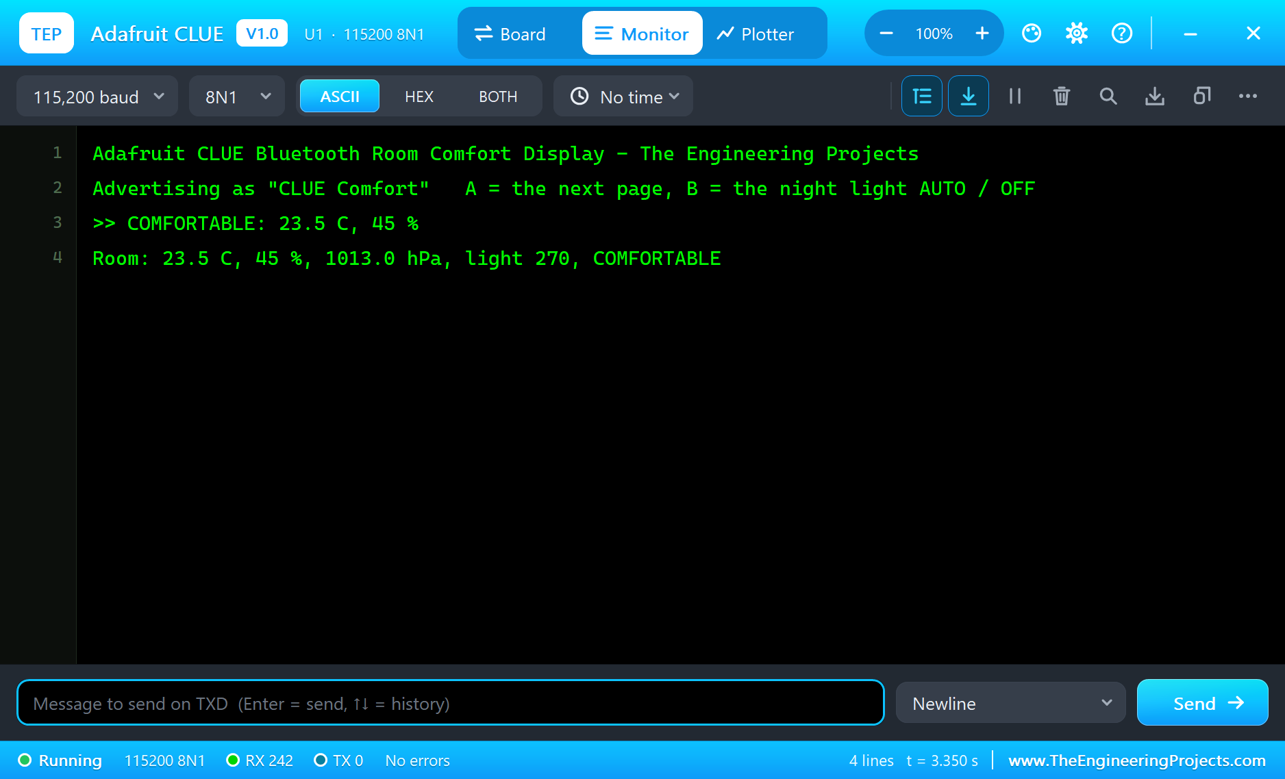
Connect the Phone
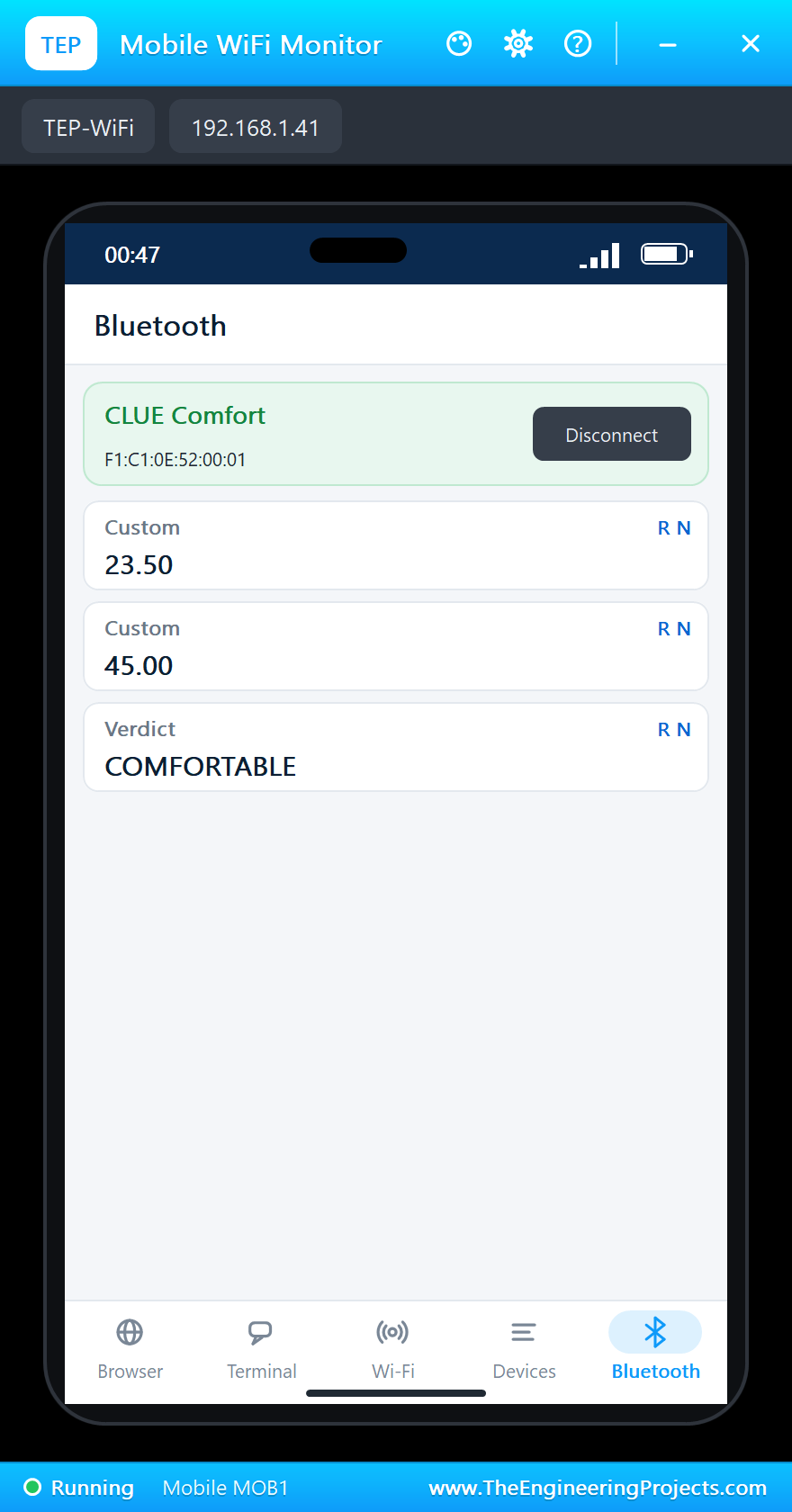
On the phone open the Bluetooth app, press SCAN and connect to "CLUE Comfort":
A Warm Room
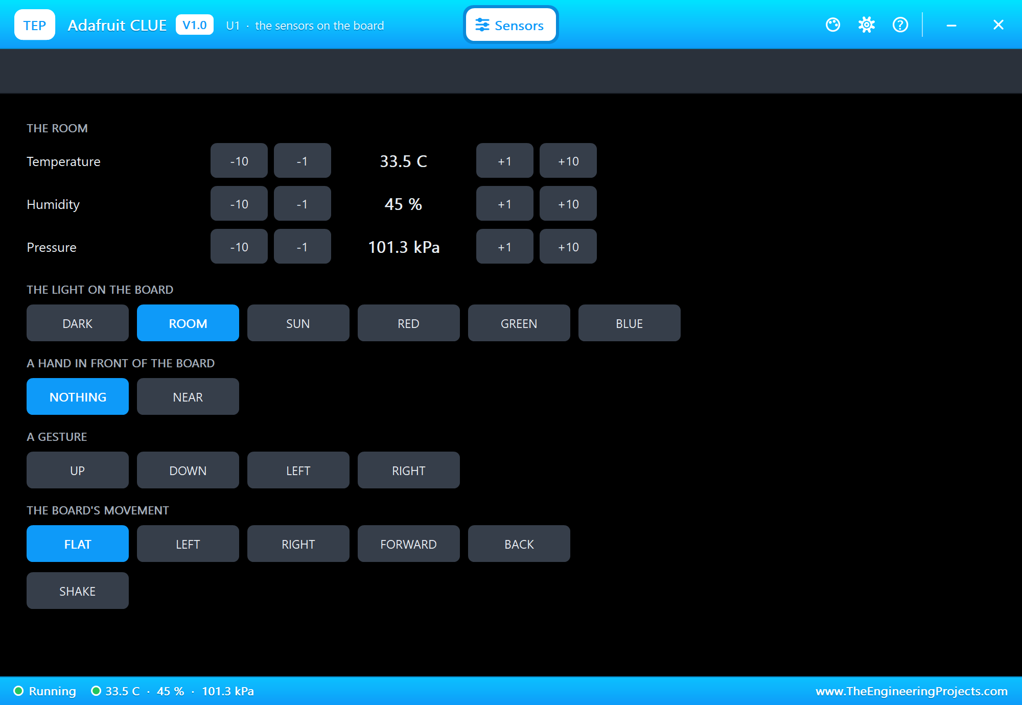
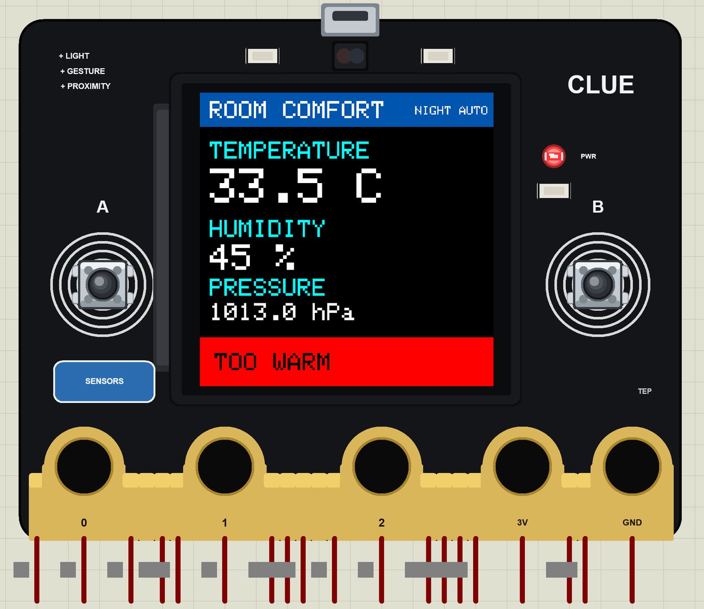
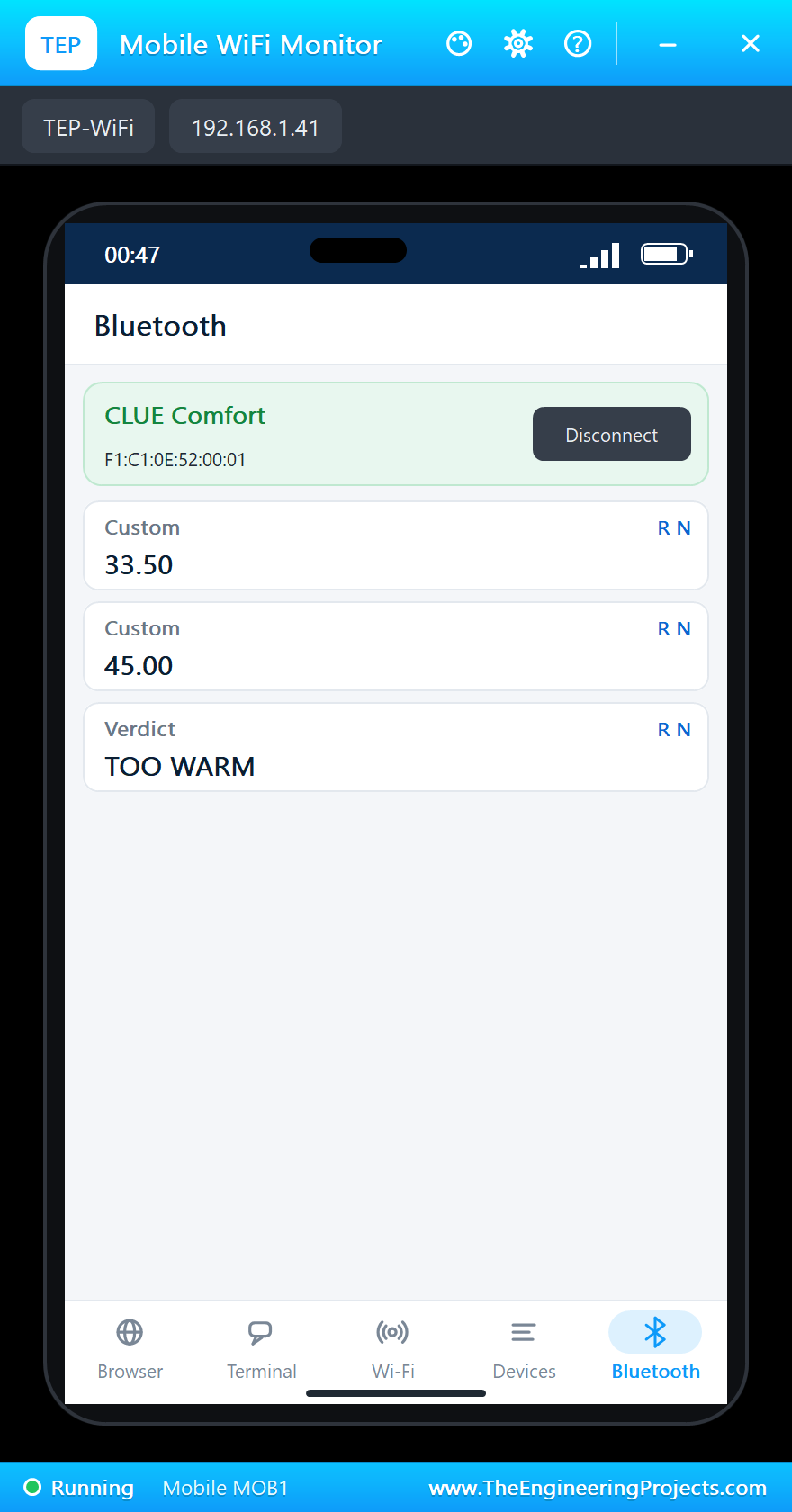
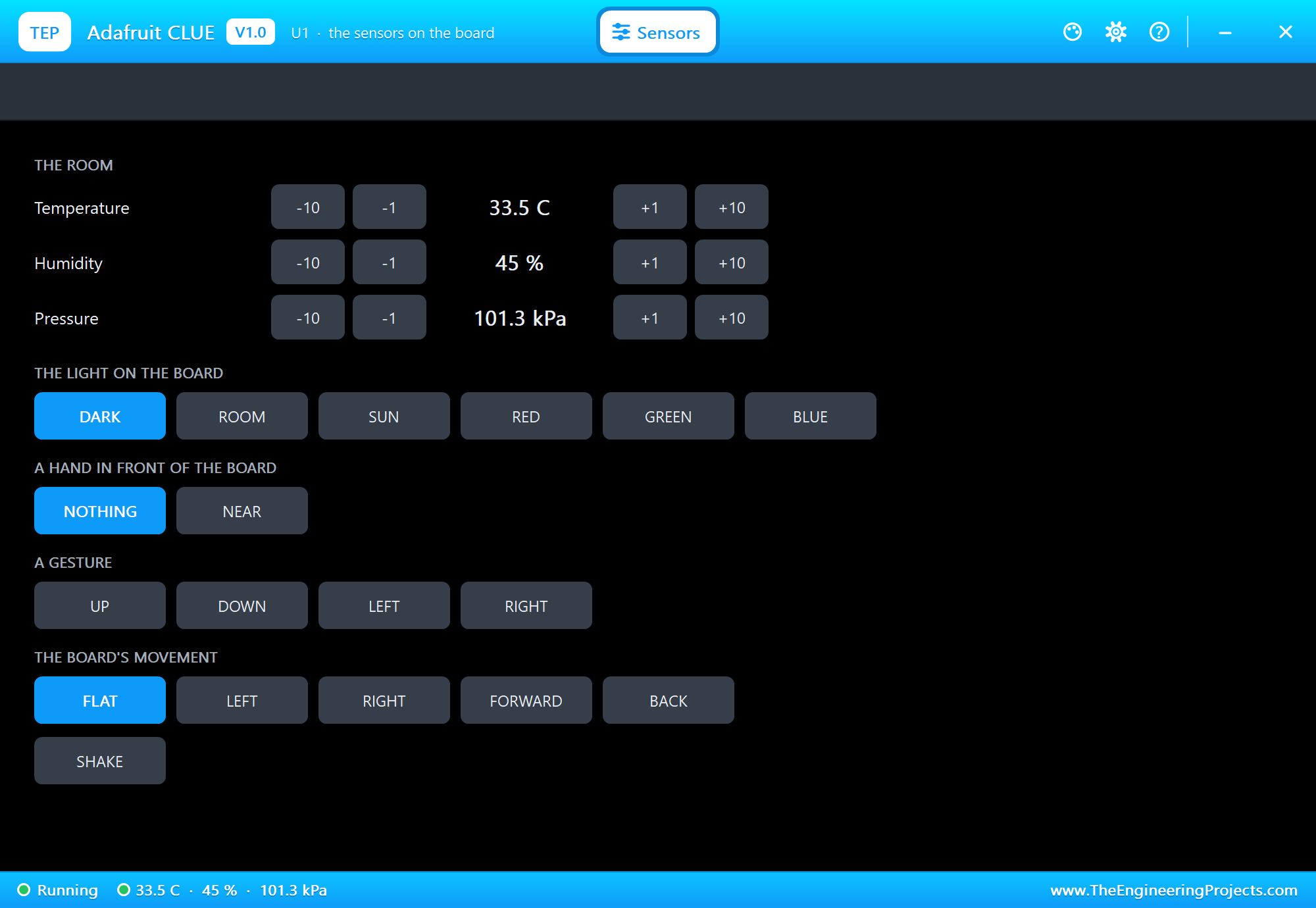
In the Sensors window make the room 10 C warmer: 33.5 C is TOO WARM, the box turns red, the red LED blinks and the phone gets the new values:
The Graph and the Night Light
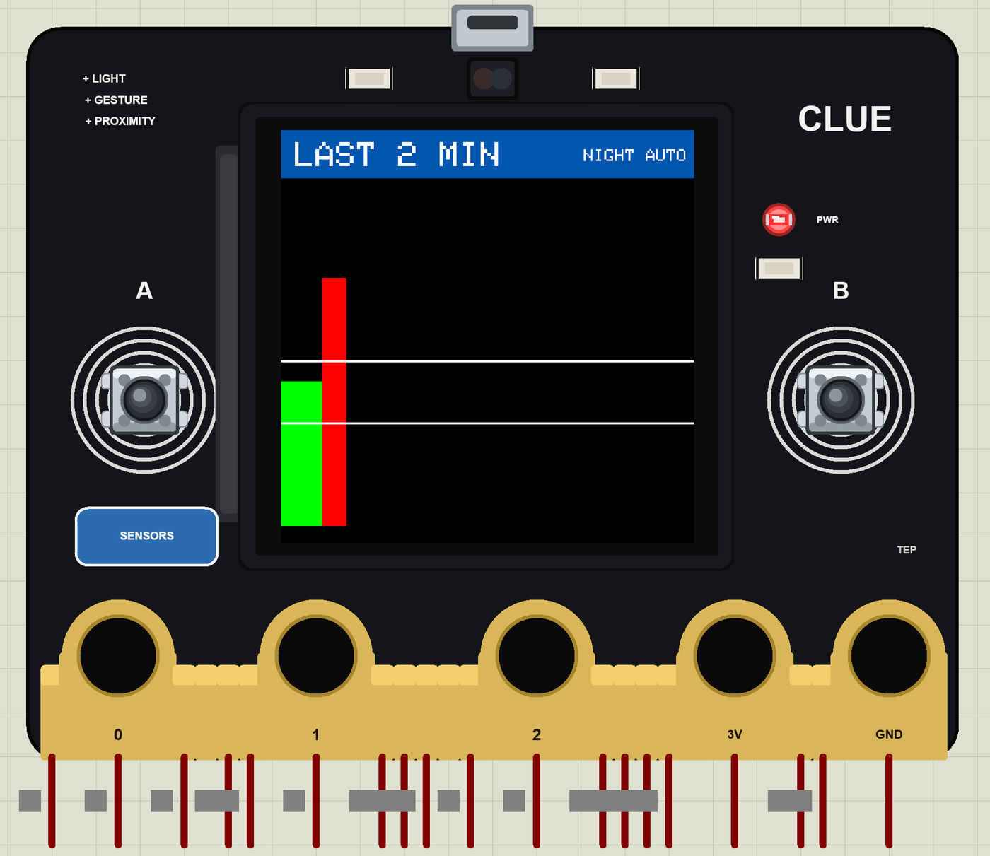
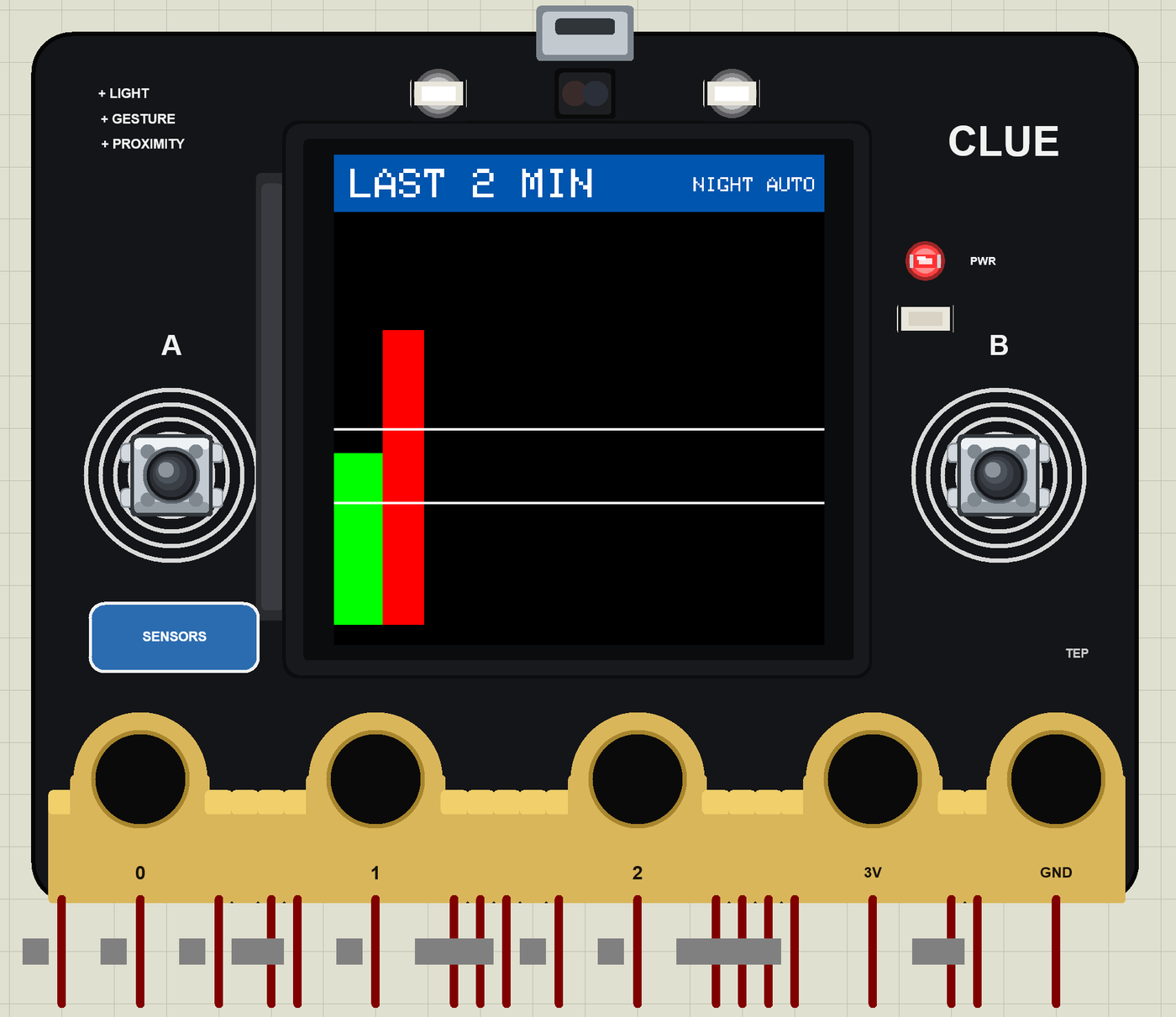
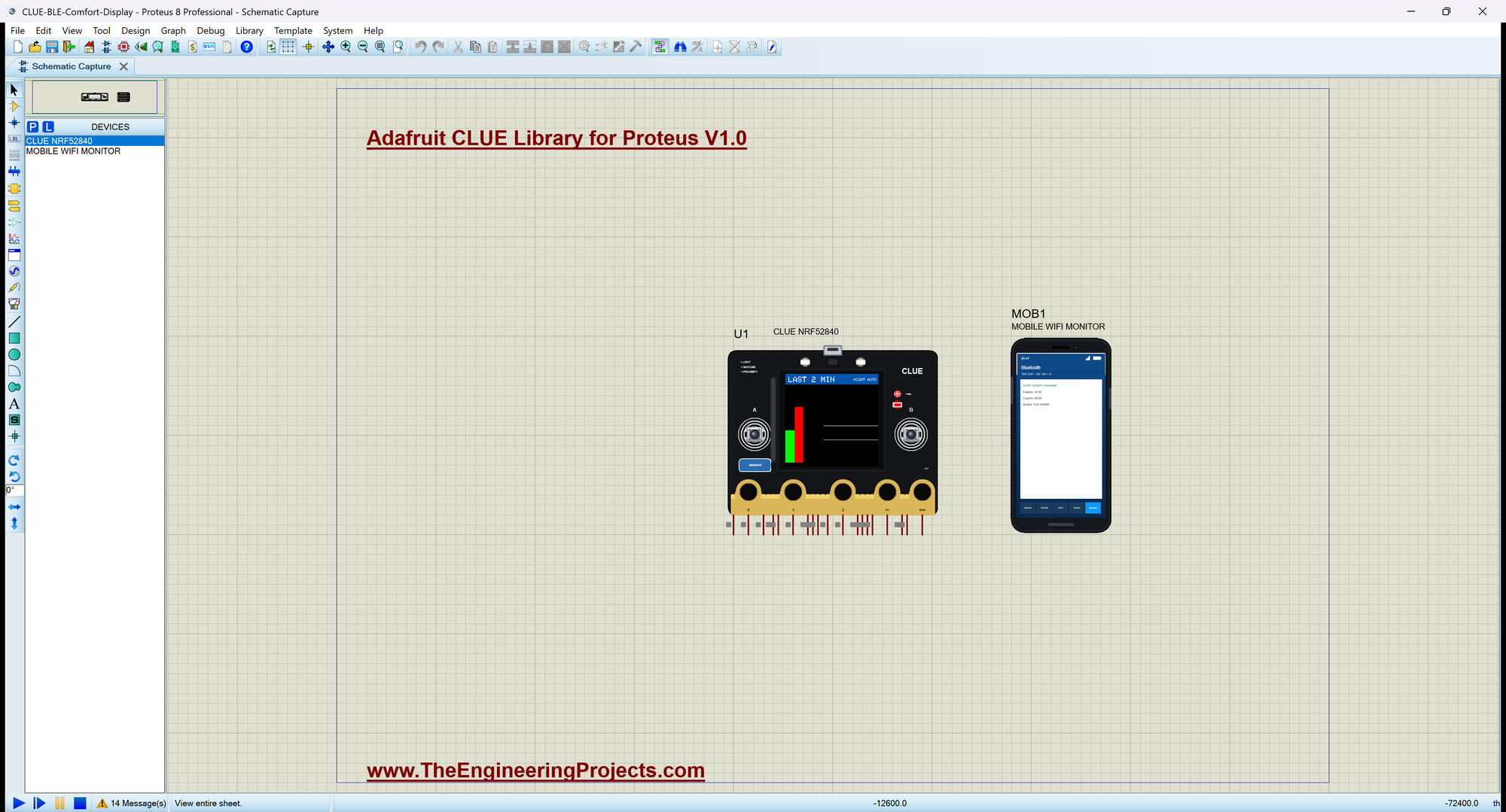
Click button A: the graph shows the step from green to red. Then click DARK in the Sensors window: the room is dark and the white LEDs light. Here is the complete circuit while the simulation runs:
Back to Normal
Click button B: the night light is OFF. Button A brings back the readings, and 10 C colder makes the room COMFORTABLE again:
Phone connected
Room: 23.5 C, 45 %, 1013.0 hPa, light 270, COMFORTABLE
>> TOO WARM: 33.5 C, 45 %
Room: 33.5 C, 45 %, 1013.0 hPa, light 270, TOO WARM
>> BUTTON A: the graph
Room: 33.5 C, 45 %, 1013.0 hPa, light 270, TOO WARM
>> DARK: the night light ON
>> BUTTON B: the night light OFF
>> the night light OFF
>> BUTTON A: the readings
Room: 33.5 C, 45 %, 1013.0 hPa, light 6, TOO WARM
>> COMFORTABLE: 23.5 C, 45 %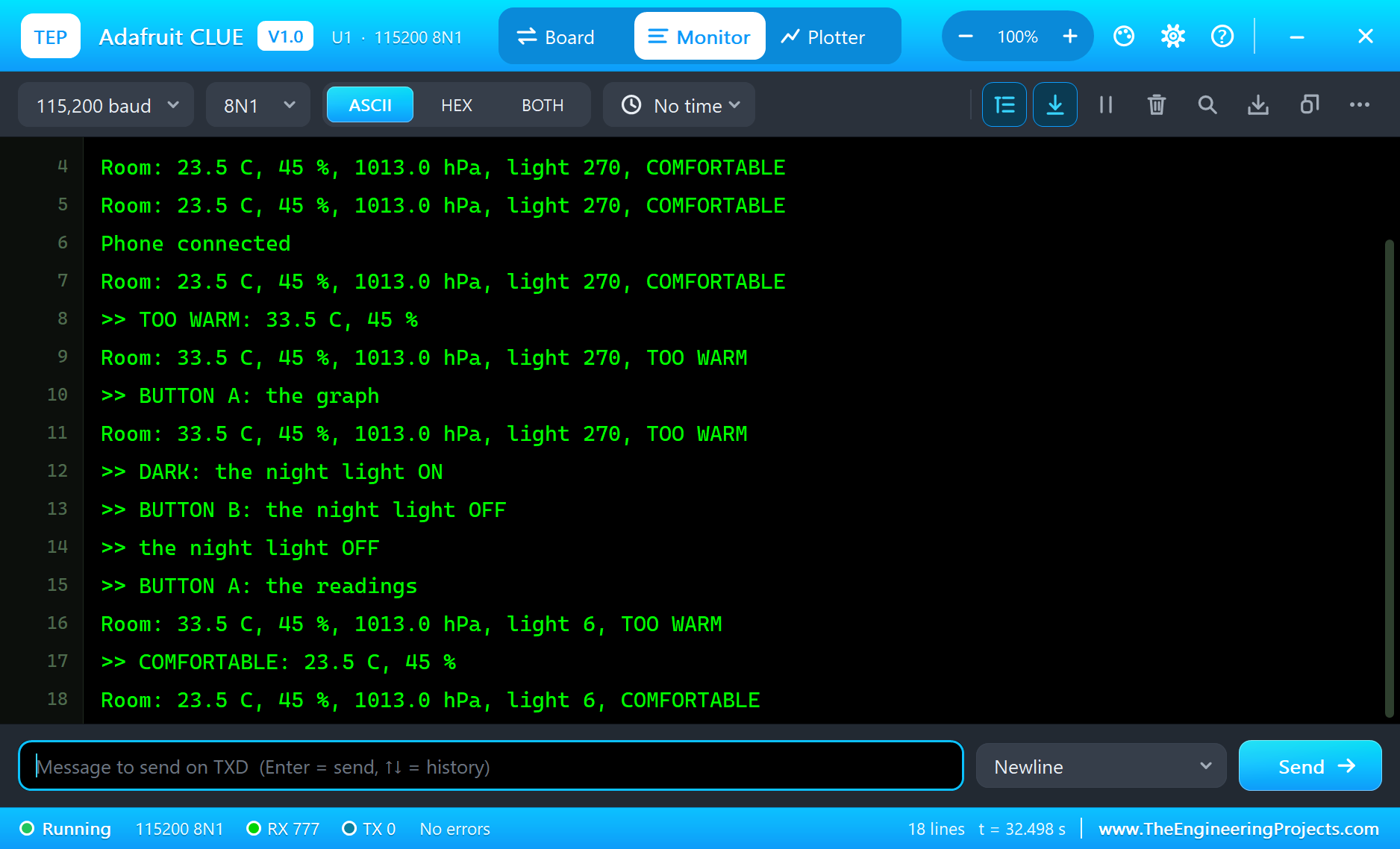
What Makes a Room Comfortable?
Most people feel comfortable indoors between about 20 and 26 C, depending on their clothes and activity. Humidity matters too: below about 30 % the air feels dry on the skin and in the throat, and above about 60 % it feels stuffy and mould can grow. The sketch keeps these limits as constants at the top, so you can adapt them to a bedroom, a server room or a greenhouse.
Why Show Pressure?
Pressure does not change how a room feels, but it is a classic part of a weather station. A falling pressure over a few hours often means worse weather is coming; at sea level the average is about 1013 hPa. The CLUE shows it on the first page so the display doubles as a small barometer.
The ST7789 Display
The ST7789 is a controller with its own memory for 240 x 320 pixels at 18 bits each. The sketch sends commands and pixel data over SPI: a window (CASET and RASET) and then the colours for it. Adafruit_GFX turns text, lines and rectangles into such windows. Because the controller keeps the picture, the processor only sends what changes - the reason a small chip can drive a colour screen at all.
Colours in 16 Bits
Adafruit_ST7789 uses 16-bit colours, RGB565: 5 bits for red, 6 for green and 5 for blue. ST77XX_GREEN and the other constants are such values; the header bar in the sketch uses 0x02B5, a calm blue. To mix your own colour, tft.color565(r, g, b) converts 8-bit red, green and blue.
How Much Data Does the Screen Need?
A full 240 x 240 picture is 57,600 pixels; at 16 bits each that is 115,200 bytes - more than the whole RAM of many small boards. That is why the sketch never keeps a copy of the screen: it sends only the parts that change. A new temperature is a few hundred bytes of text, a new verdict box about 19 KB, and one column of the graph about 800 bytes. Updating only what changed keeps the display fast and the picture steady.
The APDS9960 Light Sensor
The small black sensor between the white LEDs measures red, green, blue and clear light, detects simple hand gestures and tells how close an object is. The sketch uses only the clear channel - the overall brightness - for the night light. In the Sensors window, DARK brings it down to a few counts and ROOM back to an ordinary indoor level.
Two Buttons, Many Functions
The CLUE has only A and B on its face, so a sketch has to make them count. A common pattern - used here - gives one button the navigation (the next page) and the other an action on the current state (the night light). Longer projects add a long press or a press of both buttons together for a menu; a small change to pressed() - remembering when the press began - measures how long a button was held.
Bluetooth Environmental Sensing
The Bluetooth SIG defines standard services and characteristics, so apps can understand a sensor without knowing the device. Environmental Sensing (0x181A) with Temperature (0x2A6E) and Humidity (0x2A6F) is one of them. The sketch sends the values as floats for simplicity; a strict implementation would send the standard formats - the temperature in hundredths of a degree as a signed 16-bit number.
Battery Power
The real CLUE has a 2-pin JST PH socket for a battery from 3 to 6 V - for example three AAA cells - and no charger on board, like the micro:bit. A comfort display that runs for weeks would turn the backlight off after a while (PIN_TFT_LITE LOW) and wake it with a button.
Try It Yourself
- Show the light level on the first page and dim the backlight in a dark room.
- Add a writable characteristic so the phone can change the comfort limits.
- Draw the humidity as a second line on the graph.
- Beep with tone() on the buzzer pin when the room stays too warm for 10 minutes.
Ideas to Extend the Display
- Use the gesture sensor to change pages with a wave of the hand.
- Log a whole day and show the minimum and maximum.
- Add a CO2 sensor on the I2C pins for a full air-quality monitor.
- Shake the CLUE to wake the screen, using the motion sensor.
Your Own Sketches
Write the sketch in the Arduino IDE with the board Adafruit CLUE (TEP Proteus), use Sketch > Export Compiled Binary and set the part's PROGRAM property to the .hex.
Moving to a Real CLUE
- Install Adafruit's nRF52 board package and select the CLUE.
- Keep the display code: Adafruit_ST7789 on
SPI1withPIN_TFT_CS,PIN_TFT_DCandPIN_TFT_RST, theninit(240, 240)- that is how the real board is driven too. - Read the sensors with Adafruit's libraries - Adafruit_SHT31 for the humidity, Adafruit_BMP280 for the pressure, Adafruit_APDS9960 for the light - or with Adafruit_Arcada, which wraps them all.
- Port the Bluetooth part to Bluefruit, or keep ArduinoBLE-style code if your core supports it.
- Double-click RESET to enter the bootloader if an upload fails.
The comfort limits, the pages, the night light and the service stay the same; on the real board Adafruit's core takes the place of ours.
Properties of the CLUE
| Property | What it does |
|---|---|
| PROGRAM | the sketch: a .hex from TEP Boards for Proteus (the Adafruit CLUE board) |
| MONITOR, BAUD, AUTOOPEN | the built-in serial monitor: on, its baud rate (115200), open at Run |
| TEMPERATURE, HUMIDITY, PRESSURE | the room at Run (the demo: 23.5 C, 45 %, 101.3 kPa) |
Troubleshooting
- The display stays black: call
tft.init(240, 240)and setPIN_TFT_LITEHIGH. - The picture is shifted: use
init(240, 240), not a 240 x 320 init. - The phone's list is empty: call
BLE.begin(), set a local name andBLE.advertise(); callBLE.poll()in the loop. - A sensor reads 0: call its
begin()first. - analogRead reads the wrong input: pass the pin number - A0 is D12, A2 is D0.
Limitations of the Simulation
- SPI on the edge is not available: the SPI bus drives the display, so P13 to P15 are plain GPIO here.
- The NeoPixel, the buzzer, the microphone, the QSPI flash and the battery socket are not modelled; one phone is the central.
- The sensors come through the board package's sensor libraries; the real CLUE uses other chips with Adafruit's libraries.
- Your sketch gets 8 KB of RAM in the simulation, and int is 16 bits there.
- Adafruit and CLUE are names of Adafruit Industries, nRF52840 of Nordic Semiconductor ASA, micro:bit of the Micro:bit Educational Foundation and Arduino of Arduino; this library is not made or endorsed by them or by Labcenter.
- Tested in Proteus 8.5 in November 2026 (the demo as shipped, about 32 s of simulation). Proteus 7 is not supported.
So, that was all about the Adafruit CLUE Library for Proteus. I hope it helps you design your screens and try your Bluetooth ideas in a simulation before the board is on your desk. If you have any questions, ask in the comments and I will help you out. Till the next tutorial, take care and have fun!