Hello friends, I hope you all are doing great. In today's tutorial, we are gonna design a project named DC Motor Control using XBee & Arduino in Proteus ISIS. I have shared the complete code and have also explained it in detail. You can also download the complete working Proteus Simulation given at the end of this tutorial. In this project, I have designed two Proteus Simulations.
The first Simulation is of Remote control in which I have used a keypad. The second simulation contains our two DC Motors and I am controlling the direction of those DC Motors with my Remote Control. XBee Module is used for sending wireless data. The code will also work on hardware as I have tested it myself. So, let's get started with DC Motor Control using XBee & Arduino in Proteus ISIS:
DC Motor Control using XBee & Arduino in Proteus
I have designed two Proteus Simulations for this project.
The First Simulation is named as Remote Control while the second one is named as DC Motor Control.
I am controlling the directions of these DC Motors from my Remote.
So, let's first have a look at Remote section and then we will discuss the DC Motor Control.
You can download both of these Proteus Simulations (explained below) and Arduino codes by clicking below button:
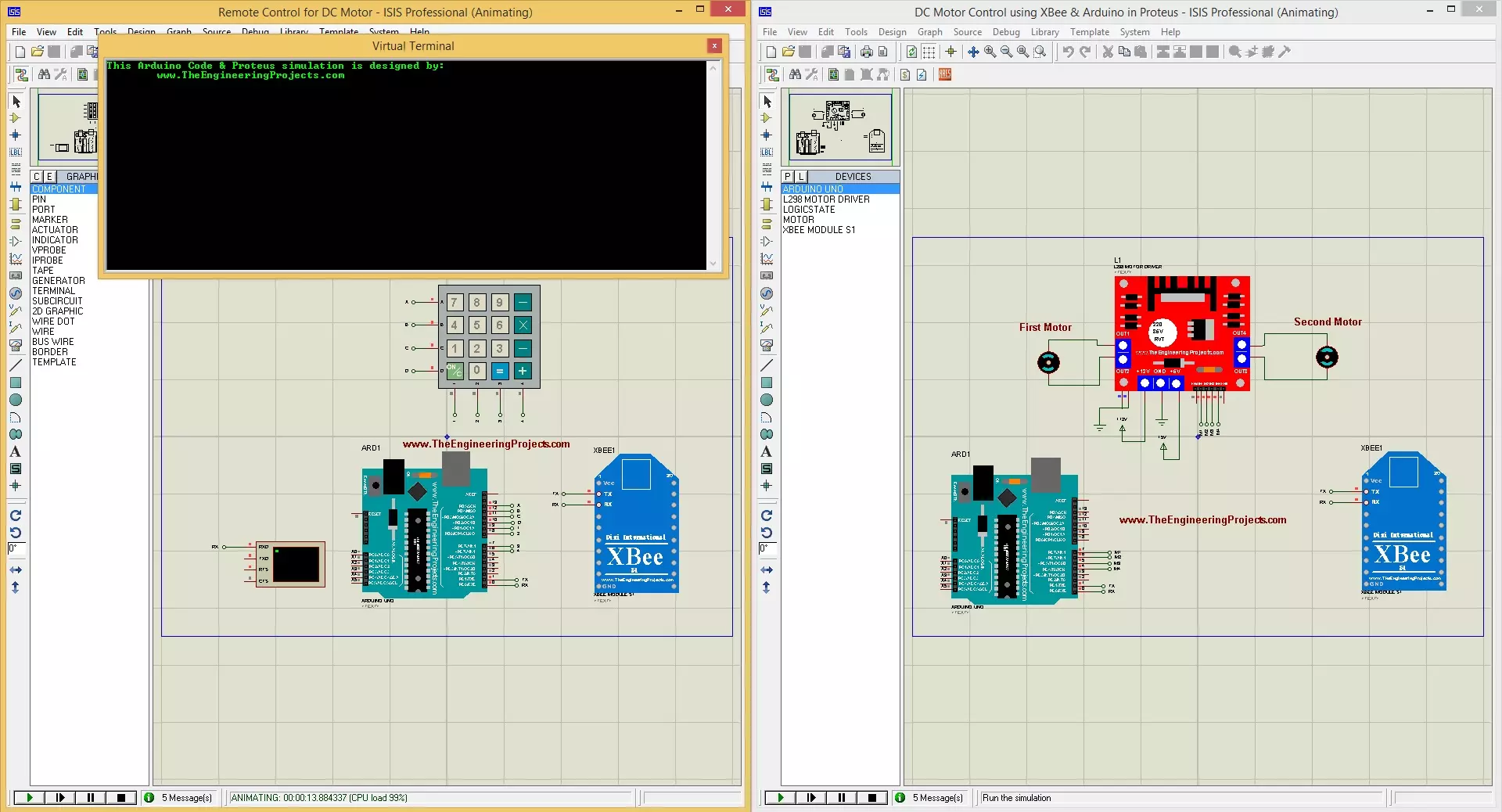
Here's the overall circuit for Remote Control designed in Proteus ISIS:
As you can see in the above figure that we have Arduino UNO which is used as a microcontroller and then we have XBee module which is used for RF communication and finally we have Keypad for sending commands.
So here we have used two DC Motors, which are controlled with L298 Motor Driver.
XBee is used to receive commands coming from Remote Control.
Now use below code and get your hex file from Arduino Software:
int Motor1 = 7;
int Motor2 = 6;
int Motor3 = 5;
int Motor4 = 4;

int DataCheck = 0;

void setup()
{
  Serial.begin(9600);
  pinMode(Motor1, OUTPUT);
  pinMode(Motor2, OUTPUT);
  pinMode(Motor3, OUTPUT);
  pinMode(Motor4, OUTPUT);

  digitalWrite(Motor1, HIGH);
  digitalWrite(Motor2, HIGH);
  digitalWrite(Motor3, HIGH);
  digitalWrite(Motor4, HIGH);

  Serial.print("This Arduino Code & Proteus simulation is designed by:");
  Serial.println();
  Serial.println("        www.TheEngineeringProjects.com");
  Serial.println();
  Serial.println();
  Serial.println();

}

void loop()
{
  if(Serial.available())
  {
    char data = Serial.read();
    Serial.print(data);
    Serial.print("      ======== >      ");

    if(data == '1'){DataCheck = 1; digitalWrite(Motor2, LOW);digitalWrite(Motor1, HIGH); Serial.println("First Motor is moving in Clockwise Direction.");}
    if(data == '2'){DataCheck = 1; digitalWrite(Motor1, LOW);digitalWrite(Motor2, HIGH); Serial.println("First Motor is moving in Anti-Clockwise Direction.");}
    if(data == '3'){DataCheck = 1; digitalWrite(Motor1, LOW);digitalWrite(Motor2,  LOW); Serial.println("First Motor is Stopped");}

    if(data == '4'){DataCheck = 1; digitalWrite(Motor3, LOW);digitalWrite(Motor4, HIGH); Serial.println("Second Motor is moving in Clockwise Direction.");}
    if(data == '5'){DataCheck = 1; digitalWrite(Motor4, LOW);digitalWrite(Motor3, HIGH); Serial.println("Second Motor is moving in Anti-Clockwise Direction.");}
    if(data == '6'){DataCheck = 1; digitalWrite(Motor3, LOW);digitalWrite(Motor4,  LOW); Serial.println("Second Motor is Stopped.");}

    if(DataCheck == 0){Serial.println("Invalid Command. Please Try Again !!! ");}
    Serial.println();
    DataCheck = 0;
  }

}
In this code, I am receiving commands from my remote and then changing the direction of my DC Motors.
When it will get '1', it will move the first motor in Clockwise Direction.
When it will get '2', it will move the first motor in Anti-Clockwise Direction.
When it will get '3', it will stop the first motor.
When it will get '4', it will move the second motor in Anti-Clockwise Direction.
When it will get '5', it will move the second motor in Clockwise Direction.
When it will get '6', it will stop the second motor.
It will say Invalid Commands on all other commands.
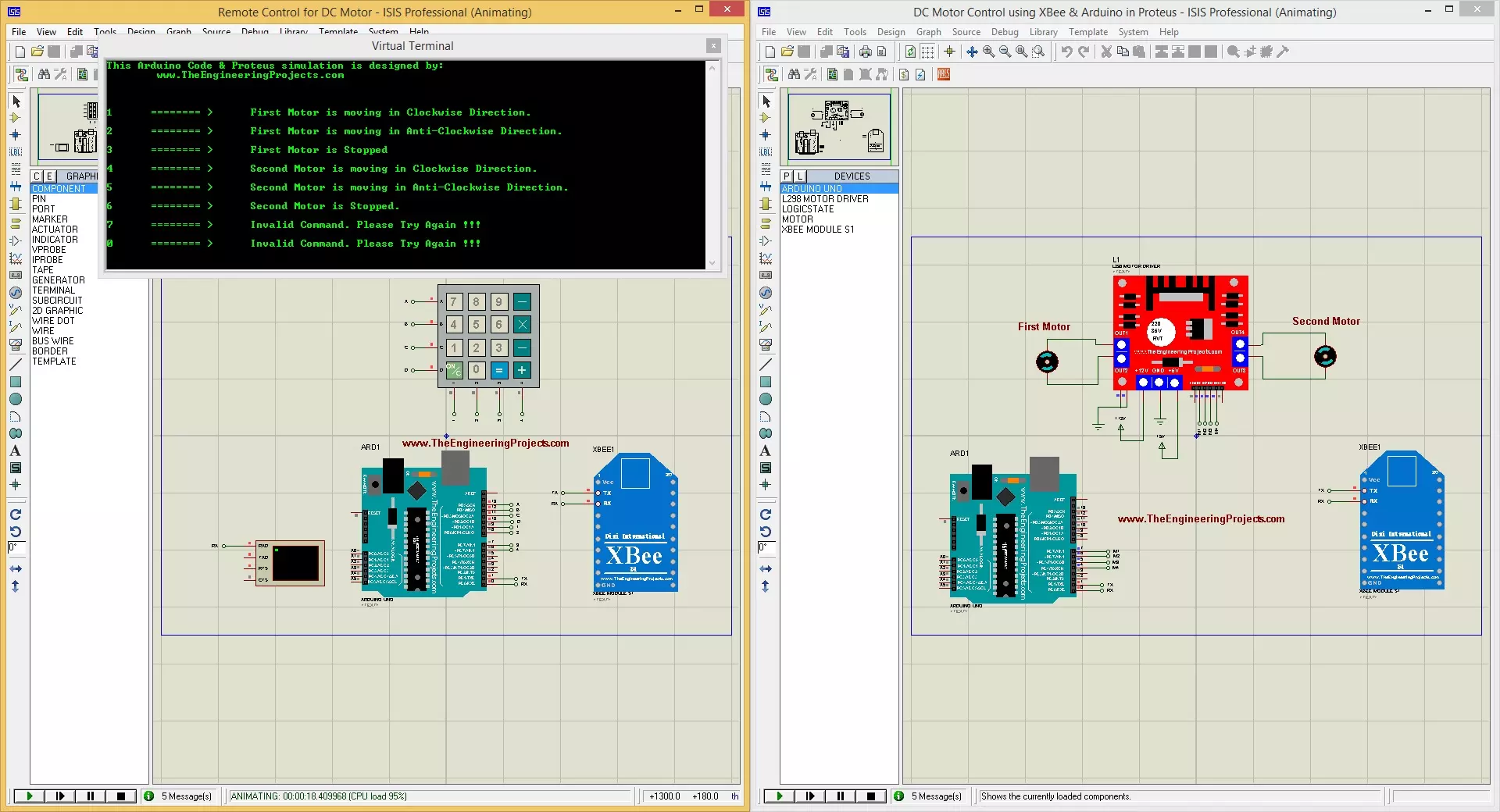
Now let's have a look at its working & results.
Working & Results
Now run both of your Simulations and if everything goes fine, then you will have something as shown in below figure:
Now when you will press buttons from keypad then DC Motors will move accordingly.
Here's an image where I have shown all the commands.
So, that's all for today. I hope you have enjoyed today's project in which we have designed DC Motor Control using XBee & Arduino in Proteus ISIS. Thanks for reading !!! :)
syedzainnasir
I am Syed Zain Nasir, the founder of The Engineering Projects (TEP). I am a
programmer since 2009 before that I just search things, make small projects and now I am sharing my
knowledge through this platform. I also work as a freelancer and did many projects related to
programming and electrical circuitry. My Google Profile+Follow
Get Connected
Comments on ‘’ DC Motor Control using XBee & Arduino in Proteus ‘’ ( 5 )
0
Says:
thank you sir, it helps me a lot to fix my issue
Reply
100
1
omparkash
Says:
Hey, is there any software needed to run xbee in proteus
Reply
100
2
haneesh
Says:
Can you provide Keypad.h file?
Reply
100
3
ajaykumar
Says:
Sir please send your email and phone number to my email .please sir
Reply
100
4
Says:
how to compile program for keypad library while am trying with keyboard library for it ,compilation error occurred with you code
Reply