Hello friends, I hope you all are doing great. In today's tutorial, I am going to share a new IR Proximity Sensor Library for Proteus. Proximity Sensors are not available in Proteus and we are sharing its Proteus library for the first time. So far, I have only shared Proteus Libraries of digital sensors but today I am sharing an analog sensor, so too excited about it.
In the next few days, I will keep on sharing Proteus Libraries of different analog sensors, so if you want any sensor in Proteus, then let me know in the comments. IR Proximity Sensors are used to detect hurdles/obstacles placed in their path. They are normally used on robots for path navigation and obstacle avoidance. So, let's have a look at How to download and simulate IR Proximity Sensor Library for Proteus:
Note:
After adding these library files, open your Proteus ISIS software, or restart it if it's already open.
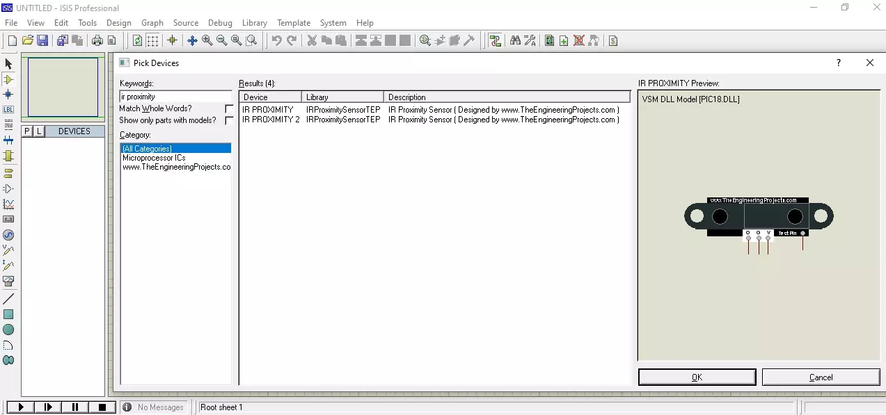
In the component's search box, make a search for IR Proximity.
If you have installed the Library successfully, then you will get similar results, as shown in the below figure:
As you can see in the above figure that we have two IR Proximity sensors.
When it comes to functionality, both sensors are exactly the same, they just have different colors.
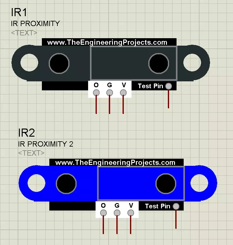
Now simply place these IR Proximity Sensors in your Proteus workspace, as shown in the below figure:
As you can see in the above figure, I have placed both of these IR Proximity sensors in my Proteus workspace.
This sensor has 4 pins in total, which are:
V ( Vcc ): We need to provide +5V here.
G ( Gnd ): We need to provide Ground here.
O ( Out ): It's an analog output signal from the sensor.
TestPin: It's solely for simulation purposes, we don't have this pin in a real IR sensor.
As we can't actually place an obstacle in front of this sensor in Proteus simulation, that's why I have used this TestPin.
If we change the value of TestPin from 0V to 5V then that means the obstacle is coming close.
Adding Sensor's Hex File
Lastly, we need to add the Sensor's Hex File, which we have downloaded and placed in the Library folder.
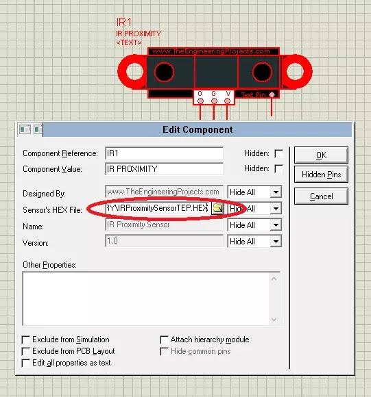
So, in order to do that, right-click on your IR sensor and then click on Edit Properties.
You can also open the Properties Panel by double-clicking on the sensor.
Here, in the Properties Panel, you will find Sensor's Hex File Section.
Click on the Browse button and add IRProximitySensorTEP.HEX file here, as shown in the below figure:
After adding the Sensor's Hex File, click on the OK button to close the Properties Panel.
Our IR Proximity Sensor is now ready to simulate in Proteus ISIS.
Let's design a small circuit, in order to understand the working of this IR Proximity Sensor.
Proteus Simulation of IR Proximity Sensor
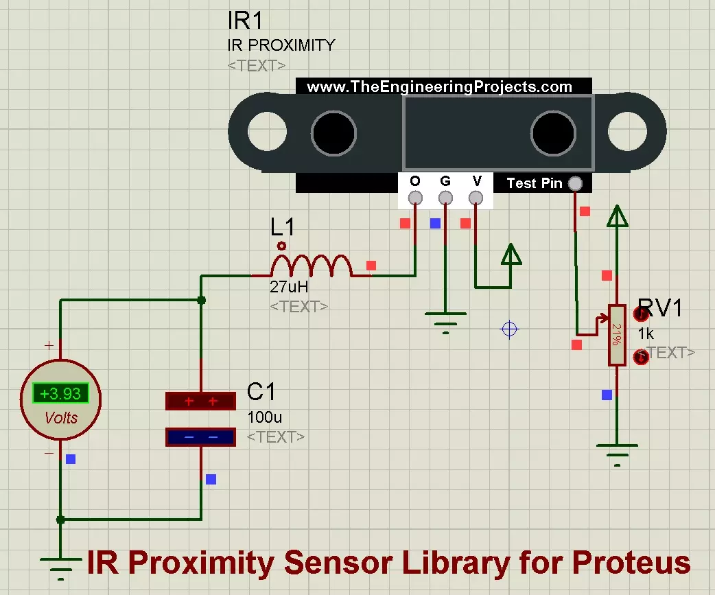
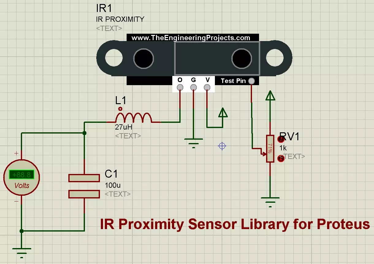
First of all, let's design a simple circuit, where I am attaching a variable resistor with the Test Pin & I am adding a Voltmeter at the Output pin, as shown in the below figure:
Using this variable resistance, we can change the voltage on Test Pin.
If TestPin has 0V, means we don't have any obstacle in front of the sensor.
If TestPin has 5V, implies that something's placed right in front of the sensor.
So, let's have a look at How the output value will change when we change the voltage on TestPin.
At the Output Pin, I have placed an LC filter, which is also not required in real hardware implementation.
But I have to use this filter in Proteus Simulation, as Proteus provides the Peak to Peak value and we need to convert that value into Vrms.
So, if you are working on a real sensor then you don't need to add this inductor or capacitor.
Now, let's run this Proteus Simulation and if you have done everything correctly, then you will get similar results:
I have shown three different scenarios in the above figure:
In the first image, the variable resistor is at 100%, thus providing 0V at TestPin. That's why we got 0V at Output and hence no obstacle detected.
In the second image, the variable resistor is around 50%, thus providing around 2.5V at TestPin. So, we are getting around 2.5V at Output and hence obstacle detected in close range.
In the third image, the variable resistor is around 0%, thus providing around 5V at TestPin. So, we are getting around 5V at Output and hence obstacle's just in front of the sensor.
I have placed this simulation in the above zip file, so play with it and don't forget to add the Sensor's Hex File.
So, that was all for today. I hope this IR Proximity Sensor Library will help engineering students in simulating their course projects. I will interface this IR sensor with Arduino and other Microcontrollers and will share their simulations. If you have any issues, then ask in the comments and I will help you out.
syedzainnasir
I am Syed Zain Nasir, the founder of The Engineering Projects (TEP). I am a
programmer since 2009 before that I just search things, make small projects and now I am sharing my
knowledge through this platform. I also work as a freelancer and did many projects related to
programming and electrical circuitry. My Google Profile+Follow
Get Connected
Comments on ‘’ IR Proximity Sensor Library for Proteus ‘’ ( 2 )
0
0755684523
Says:
Thanks for this tutorial.can you help the library of IR sensor for Proteus
Reply
100
1
0755684523
Says:
Thanks for this tutorial.can you help the library of IR sensor for Proteus
Reply