

PC817 Library for Proteus
- First of all, download this PC817 Library for Proteus by clicking the below button:
[dt_default_button link="https://www.theengineeringprojects.com/ArduinoProjects/PC817 Library for Proteus.zip" button_alignment="default" animation="fadeIn" size="medium" default_btn_bg_color="" bg_hover_color="" text_color="" text_hover_color="" icon="fa fa-chevron-circle-right" icon_align="left"]Download Proteus Library[/dt_default_button]
- It's a zip file, which will have a Proteus Library folder.
- Open this folder, and you will find these 2 Library files in it:
- OptocouplersTEP.IDX
- OptocouplersTEP.LIB
- Place these Library Files in the Library folder of your Proteus software.
- If you are unable to add Library in Proteus 7 or 8 Professional, then you should have a look at How to add new Library in Proteus 8.
- Now open your Proteus ISIS software or restart it if its already open.
- In the components search box, make a search for PC817.
- If everything goes fine, then you will get results as shown in below figure:
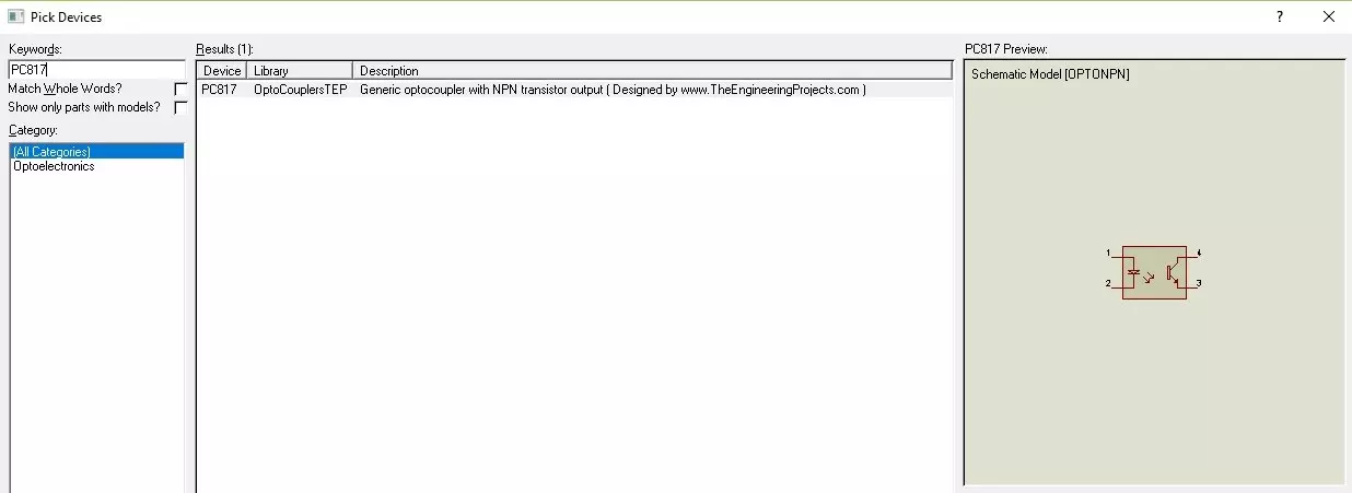
- Now place this PC817 in your workspace.
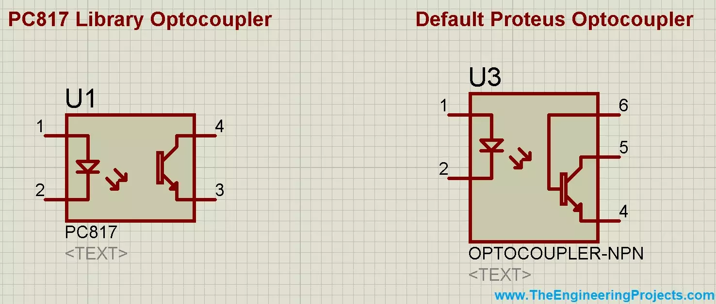
- Default optocoupler available in Proteus contains 5 Pins but this PC817 has 4 Pins, as shown in below figure:
- I have shown both optocouplers in above figure.
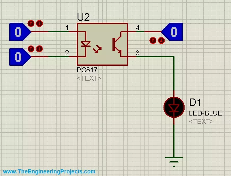
- Now let's design a simple circuit to have a look at How it works:
- So, connect three LogicState and one LED with PC817, as shown in below figure:
- Now run your Proteus Simulation and change the states of your buttons.
- Both On & Off states of PC817 are shown in below figure:
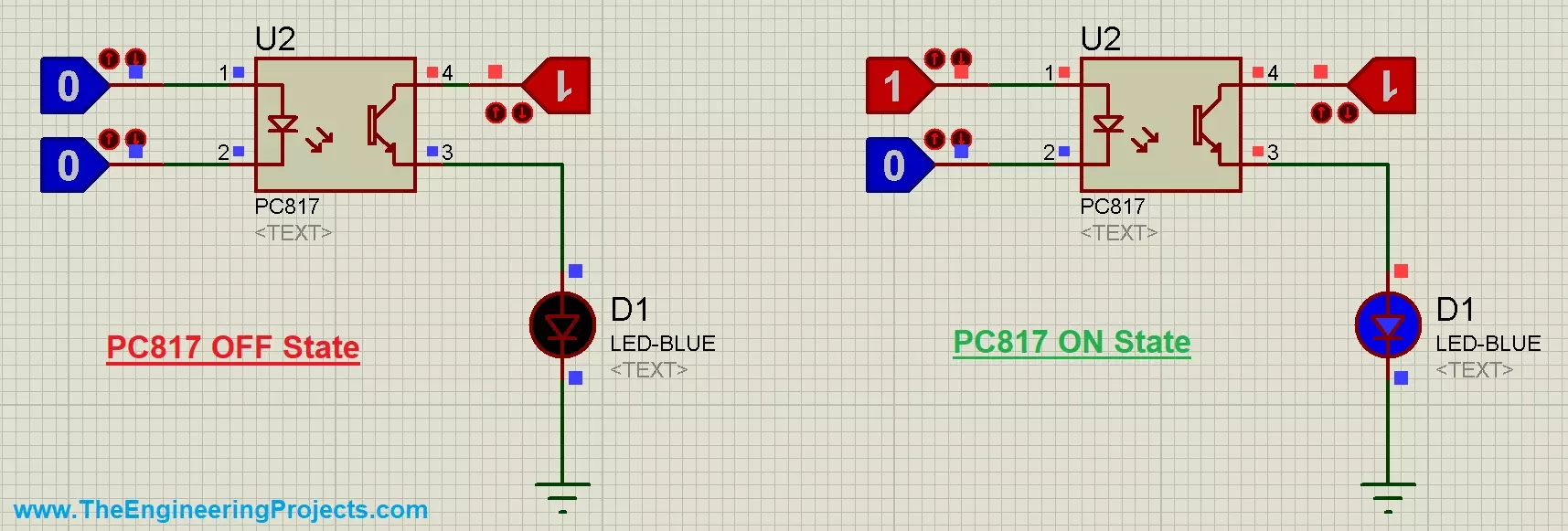
- So, that's How you can easily simulate PC817 in Proteus.
