

Hey Guys! Glad to see you here. I welcome you on board. In this tutorial today, I’m going to share the Analog PIR Sensor Library for Proteus. We have already shared the digital PIR Sensor Library for Proteus V1.0. Moreover, you should also check the latest version of PIR Sensor Library V3.0. If you don’t know what is PIR sensor, you must read this post first where I’ve briefly discussed the Interfacing of PIR sensor with Arduino.
PIR (Passive Infrared Sensor) also known as a motion sensor, is used to detect motion using infrared rays. It is used in banks for security purposes. It can detect the presence of a person by identifying their motion inside. Similarly, it is used in home automation where it detects the movement in the room, giving a signal we need to turn on the light because there is someone in the room. And when there is no motion detected, it turns off the light.
Analog PIR Sensor Library for Proteus is not available in the Proteus Library Database, and I’m sharing it, for the very first time. If you’re a regular reader of our blog, you might have read the new libraries we shared previously, if you haven’t, you can first have a look at Arduino Library for Proteus where you’ll get a hold of a simulation of Arduino Board in Proteus.
I’ll be sharing both: simple simulation in proteus and simulation of PIR sensor with Arduino Board. Besides Arduino Boards, you can also interface this analog PIR sensor with PIC and 8051 microcontrollers.
If you feel, we are missing something important that must be included in the proteus library, share your valuable suggestion in the section below. If you’re new to proteus software, check this post on how to download and install proteus software. Let’s discuss the Analog PIR Sensor Library for Proteus. Keep reading.
Analog PIR Sensor Library for Proteus
Click the link given below and download Analog PIR Sensor Library for Proteus.
Analog PIR Sensor Library for Proteus
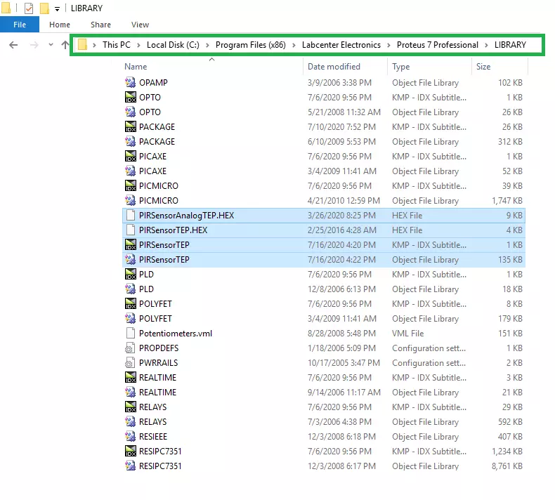
As you download the library, it comes with four files that are:
- PIRSensorAnalogTEP.HEX
- PIRSensorTEP.HEX
- PIRSensorTEP.IDX
- PIRSensorTEP
Now copy all these files mentioned above and place them into the library folder of your Proteus software.
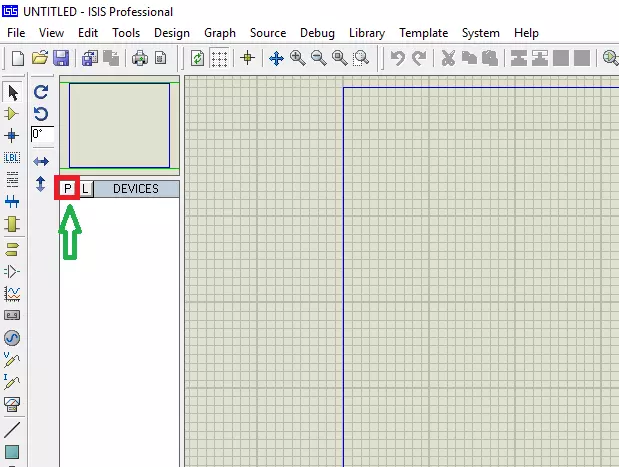
- Click ‘P’ (Pick from Libraries) as below and search for the PIR sensor analog.
- It will pop up four files of the PIR analog sensor as mentioned below.
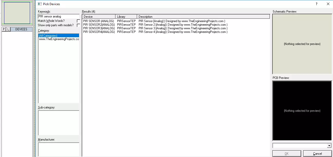
- Place all these four files in the proteus workspace. As you place them, it will appear as follows:

- I have added four PIR Analog Sensor files in the proteus workspace that you can use as you like better.
- These sensors are the same in terms of working but they all come in different colors just to make them attractive.
- The first one appears in berylline color, the second one is green, the third is red and the fourth one is blue.
PIR analog sensor contains four pins as follows:
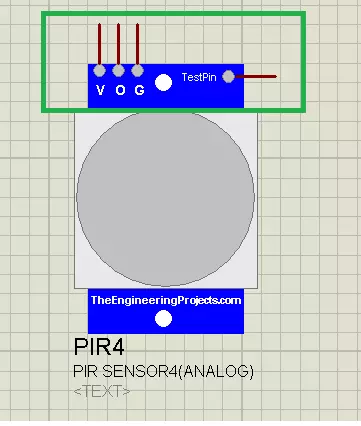
- Vcc = This is a voltage supply pin where we apply 5V to power the sensor
- O = second is the OUT pin where we get the output of the PIR sensor indicating whether or not this PIR sensor has detected the motion.
- G = third is the ground pin which is attached to the ground voltage.
- TestPin = forth is TestPin we need to add in Proteus simulation only. You won’t find this pin mounted on the sensor in real. We have to add this pin because without this pin we cannot detect the motion in proteus simulation. When this TestPin is HIGH it shows the motion is detected and when it is LOW it shows no movement.
After adding these four files to the proteus workspace, we need to include the HEX file in the PIR sensor. You will find this PIRSensorAnalogTEP.HEX file in the library folder of your Proteus software.
- You can add the HEX file in two ways. Right-click the sensor and look for ‘edit properties’ or double-click the analog sensor.

- Now look for the HEX file that you have pasted in the library folder below.
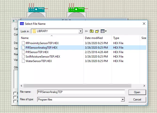
- After adding this file, click ‘OK’ … now you’re done. You’ve added the HEX in the analog PIR sensor. You can now use this PIR sensor simulation in Proteus.
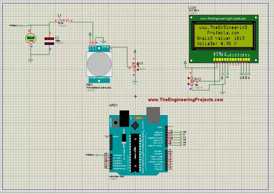
- We’ll design and attach a simple LC circuit with this PIR sensor to understand the working and simulation of the library of this sensor.
Attach the sensor’s analog output pin (O) with the LC circuit through a voltmeter using a voltmeter. Ground (G) pin and apply 5V to the (Vcc) voltage supply pin. Now connect the variable resistor with the TestPin, which will help identify the motion in the surrounding.
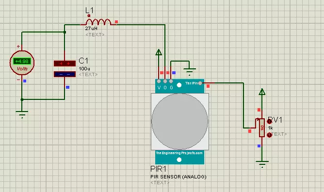
The value of this variable resistor is related to the voltage appearing across the voltmeter. When resistance is 100% the voltage appearing on the voltmeter will be zero which shows no motion detection and when resistance is 0% the voltage value across a voltmeter will be 4.97V as below, indicating the presence of motion. Both output voltage and resistance are inversely related to each other.
- We need to design and connect this LC circuit with the PIR sensor due to the peak-to-peak value we receive on proteus. This peak-to-peak value needs to be converted into Vrms using this LC circuit.
This is it. This is the proteus simulation of the PIR analog sensor. We treasure to announce we’ve added this new library to the proteus database for the very first time.
PIR Analog Sensor with Arduino UNO
- It’s time to connect the PIR Analog Sensor with the Arduino Board.
- To do this, we’ll connect the output voltage we get on the voltmeter with the analog input pin of the Arduino board.
- You should also have a look at PIR Arduino Interfacing.
- When resistance is maximum, the voltage will be zero, thus giving an equivalent analog value of 0019 and when resistance is zero, the voltage across the voltmeter is 4.98V and gives an equivalent 1019 analog value on the LCD attached with the Arduino Board.
- You can download LCD Library for Proteus, which I have used in the above simulation.
This is it for today. Hope you find this tutorial helpful. If you’re unsure or have any questions, you can pop your comment in the section below, I’ll help you the best way I can. Thank you for reading this article.
