


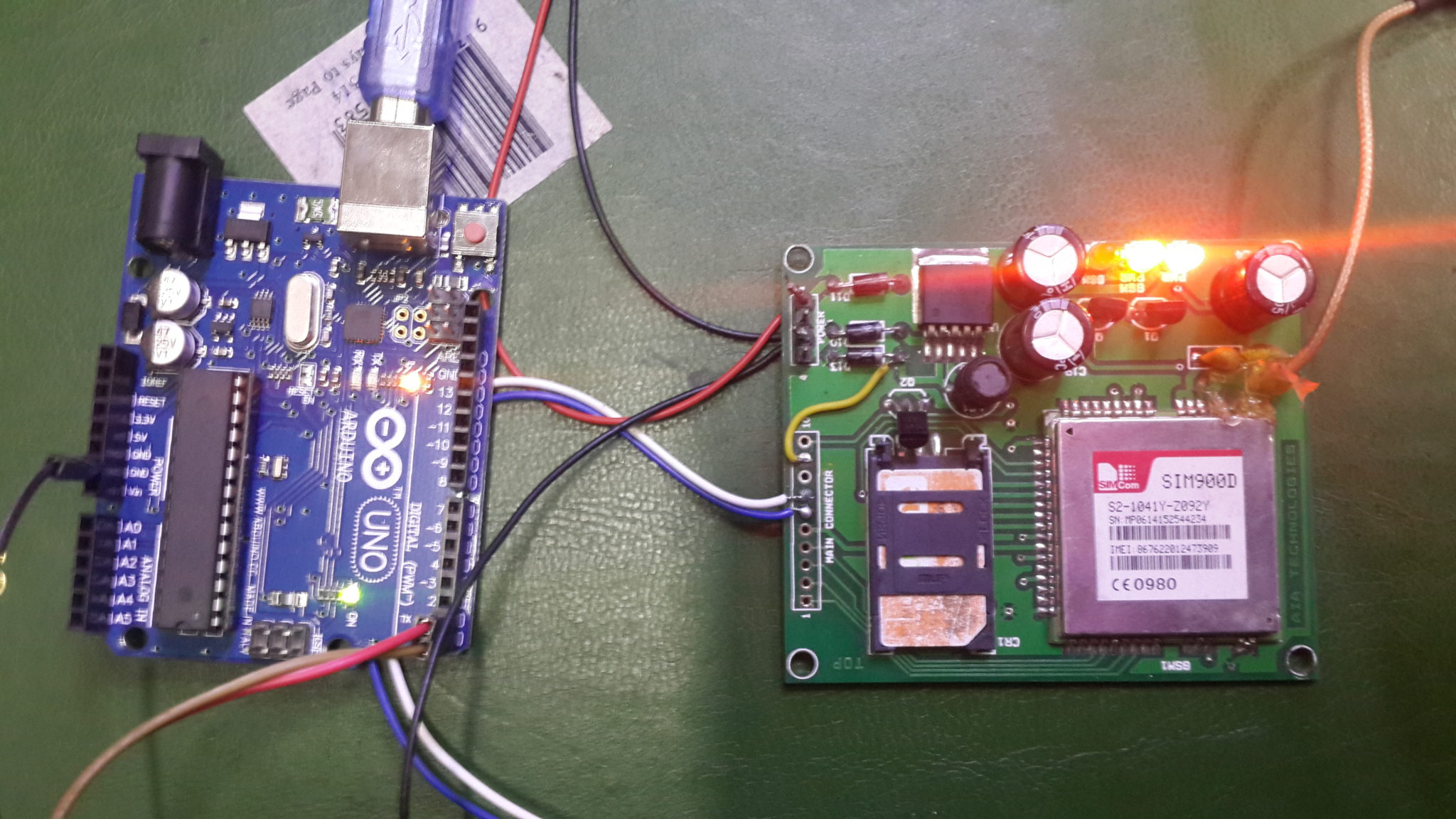
Receive SMS with AT Commands using Sim900 and Arduino


Hello friends! Today we will receive SMS messages with a SIM900 modem and an Arduino. In the earlier SMS sending tutorial, Arduino initiated a command and supplied message text. Receiving is different because a message can arrive at any time, including while the program is handling another modem response.
SIM900 Simulation Libraries
Latest library: SIM900A Library for Proteus V1.1 (October 2026)
Helping Tools
- Serial Monitor Advance: a serial terminal window for the UART of your board
- Serial Monitor Expert: the serial monitor with extra debugging tools
- LCD Library for Proteus V3.0: 16x2, 20x4 and I2C LCDs to show your readings
We will begin by checking the serial connection, configure text-mode notifications and inspect the sender and message body. Then we will look at the mistakes that make a receiver unreliable: incorrect line endings, searching for single letters instead of complete responses, fixed character positions and unbounded waiting loops.
The original screenshots remain as examples of the historical project. The serial bridge below is a new diagnostic sketch that lets you inspect the modem directly. It deliberately does not operate relays or other equipment. Establishing a reliable message boundary comes before using incoming text as an application command.
What You Need Before Receiving an SMS
Use an Arduino Uno, a SIM900-based board, a suitable antenna, a supported SIM and an appropriate power supply. SIM900 is a GSM/GPRS-generation device. Confirm that the local operator still offers a compatible network and SMS service for the selected SIM; the presence of a newer mobile network does not establish compatibility with this older modem.
A SIM900 module and a development shield are not electrically interchangeable. The shield may include regulation, level conversion and a power-key circuit. The bare module requires those provisions externally. Follow the board's schematic and manual rather than connecting power based only on a photograph of a different breakout.
SIMCom's SIM900 hardware-design document specifies the module supply range and transient-current requirements. The bare module's supply is not simply the Arduino's 5 V pin. A weak supply can reset the modem during radio activity even when its startup LEDs initially look normal.
Separate USB diagnostics from the modem UART
The Uno has one hardware UART shared with its USB serial interface. Connecting every diagnostic message and modem command to that same path can cause contention or send debugging text to the modem. For this introductory bridge, we will use SoftwareSerial on D7 and D8 for the modem while keeping USB Serial for the computer.
| Connection | Purpose |
|---|---|
| Modem TX to Arduino D7 | Arduino receives modem output |
| Arduino D8 to modem RX through the required interface | Arduino sends commands at a compatible logic level |
| Common signal ground | Provides the UART voltage reference |
| Dedicated appropriate modem supply | Supports the board's radio-current demand |
| Arduino USB to computer | Provides the diagnostic terminal connection |
Verify the UART voltage ratings on both sides. A 5 V Arduino output should not be applied directly to a lower-voltage modem input merely because both use serial data. Some shields already include the conversion; others do not. Keep the required interface in the wiring plan.
Upload a Simple Serial Bridge
The following sketch forwards bytes between the computer and modem. It does not automatically configure the modem, interpret SMS messages or send replies. This limited role makes it useful for confirming each command before implementing an automatic receiver.
#include <SoftwareSerial.h>

SoftwareSerial modem(7, 8);  // Arduino RX, TX

void setup() {
  Serial.begin(9600);
  modem.begin(9600);
  Serial.println("SIM900 bridge ready. Send commands with CR.");
}

void loop() {
  while (modem.available() > 0) {
    Serial.write(modem.read());
  }
  while (Serial.available() > 0) {
    modem.write(Serial.read());
  }
}
This example assumes that the modem's active UART baud rate is 9600. Match the actual configuration rather than repeatedly changing random terminal settings. Arduino's SoftwareSerial documentation explains the library's capabilities and limitations. For a more demanding receiver, a board with a separate hardware UART is usually easier to service reliably.
Open the Serial Monitor at 9600 baud and choose a line-ending setting that sends carriage return. Type AT and look for a complete response. If the modem echoes the command, that is not the same as acknowledging it; the echoed text and the final result are separate parts of the transcript.
Carriage return, newline and null are different
In Arduino C++, "AT\r" contains a carriage-return character after AT. "ATr" contains the ordinary letter r and is not equivalent. Likewise, \n is a line feed and \0 is a null character used to terminate a C string in memory. The old explanation incorrectly called newline a null character.
When building a command in code, write the intended control character explicitly. For example, modem.print("AT\r"); sends AT followed by carriage return. Avoid printing additional debugging labels to the modem port, because those labels become part of its input stream.
Configure the SIM900 for Text Notifications
The following commands cover the basic inspection and configuration steps. Wait for each command's complete final response before issuing another. If a command fails, keep its error text and investigate that failure instead of continuing as though the configuration succeeded.
| Command | Purpose |
|---|---|
| AT | Check command-channel communication |
| ATE0 | Disable command echo |
| AT+CPIN? | Inspect SIM readiness |
| AT+CREG? | Inspect network registration |
| AT+CMGF=1 | Select SMS text mode |
| AT+CNMI=? | Inspect supported indication settings |
| AT+CNMI=1,2,0,0,0 | Request the direct-delivery behavior used in the original tutorial |
Consult the matching firmware's SIM900 AT-command manual for parameter details. The important distinction is that +CMT: carries a directly delivered message, while +CMTI: identifies a stored message location. They require different handling and should not be treated as interchangeable prefixes.
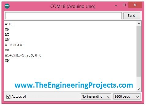
The retained configuration screenshot shows acknowledgments from the historical example. An OK response means that a particular command was accepted; it does not prove that every future message will arrive or that the module has adequate signal and supply conditions.
Inspect a Directly Delivered Message
Send a short, ordinary text message to the SIM fitted in the modem after the setup is confirmed. Watch the complete transcript without running an automatic response action. A direct-delivery notification contains a header and then message data, with line separators between them.
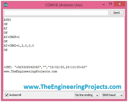
The original screenshot shows a notification beginning with +CMT:, including sender information followed by the text. Keep the entire header while learning. The sender, timestamp and optional fields are not guaranteed to occupy the same character offsets in every message.
A domestic number, an international number and an alphanumeric sender can have different lengths. Taking characters four through sixteen because one sample happened to fit that range is not a parser. It is a special case that can truncate a number or include punctuation from a neighboring field.
Extract fields by structure
For an intentionally restricted text-mode example, locate the quoted sender field according to the header grammar and copy it into a bounded destination. Check that opening and closing quotes are present, that the result fits, and that unexpected trailing fields are handled deliberately. Preserve the original value separately if later normalization is needed.
Do not remove a leading plus sign simply to make phone numbers look alike. Normalization needs a defined numbering policy and context. For a display-only receiver, preserving the received sender string is often more useful than inventing a local format that changes its meaning.
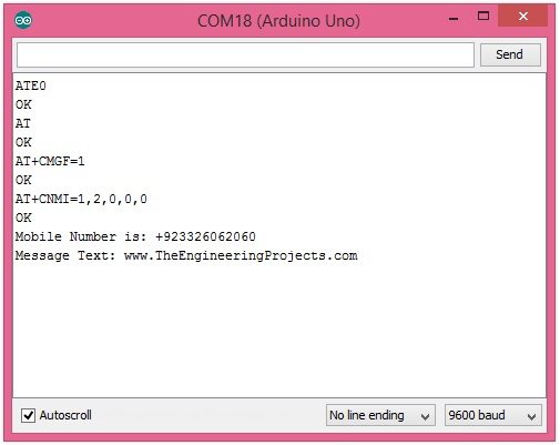
The final historical screenshot demonstrates separate display of sender and body. That is the intended result, but one successful message is not sufficient evidence that the parser handles different lengths, empty fields, line breaks or a message that arrives during another modem transaction.
Design the Automatic Receiver as a State Machine
Once manual reception works, give the automatic receiver explicit states. A state identifies what the next bytes are allowed to mean. Without that context, a line containing OK could be confused with a command acknowledgment even when those letters belong to an SMS body.
| State | Expected work | Failure to handle |
|---|---|---|
| Idle | Recognize notifications and queued commands | Unknown or malformed line |
| Waiting for command result | Collect response lines until final status | Error or deadline expiry |
| Reading SMS header | Validate and store sender-related fields | Missing delimiters or oversize header |
| Reading SMS data | Collect the supported body representation | Overflow or unsupported encoding |
| Message ready | Pass a complete validated record to the application | Application queue full |
This table is a design outline, not a drop-in parser. A first implementation may deliberately support only short single-line text messages. State that restriction and reject unsupported input cleanly. General SMS handling must account for encoding, multipart messages and body framing rather than assuming that two newline characters always finish the message.
Unsolicited modem notifications can appear while a command is outstanding. The receiver needs to recognize them without discarding the pending command's response. Keep one controlled command transaction at a time and route unrelated notifications to their own handling path.
Compare complete results
The old response routine stopped when it saw the letter K or R. Those characters can occur in unrelated text, so they do not identify OK or ERROR reliably. Compare complete recognized result lines in the correct state, and preserve extended error information rather than reducing every failure to one generic message.
A command timeout also needs an explicit deadline. If the modem never responds, the program should report a failure and return to a defined recovery state. An endless loop waiting for a character can make the entire application appear frozen even though the microcontroller continues executing instructions.
Buffer Size and Timing Matter
A serial stream arrives incrementally. A header may be split across several calls to available(), and several lines may already be waiting by the next call. Treat the UART as a stream of bytes, not as a function that returns one complete SMS each time you check it.
At 9600 baud with 8N1 framing, a character occupies approximately ten transmitted bits. The line can therefore deliver about 960 characters per second, or one character every 1.04 ms. A 100 ms delay can allow roughly 96 characters to arrive while the main loop is doing no reception work.
If a particular receive buffer holds 64 bytes, that illustrative delay can exceed its capacity. Increasing the buffer may buy time but does not fix a receiver that neglects input for long periods. Drain the stream frequently and keep message processing separate from byte acquisition.
Bound every copy operation
A 192-byte character array can hold at most 191 content bytes plus its terminating null when used as a C string. Check capacity before writing the next byte. On overflow, discard or quarantine the incomplete record through a defined resynchronization procedure; never treat the truncated text as a valid control command.
Use separate bounds for the sender, header and body. A sufficiently large body buffer does not protect a smaller sender buffer. Also distinguish byte count from human-readable character count when a message encoding can use more than one byte per character.
Consider Stored-Message Notifications
A stored-message workflow can be easier to recover after a temporary interruption. Instead of assuming the complete message must be consumed immediately from a direct notification, the application receives a storage identifier and index, then requests that record. Keep the storage name with the index because the number alone may not identify the same location in every memory selection.
For SIM900, the relevant command family includes AT+CPMS for storage selection, AT+CMGR for reading and AT+CMGD for deletion. Use the modem manual to select supported settings. Delete only a specifically processed message when the application's retention policy allows it, rather than issuing a broad delete-all command during every startup.
A memory can fill, and notifications may be missed while the microcontroller is disconnected. Plan a startup reconciliation step that inspects the intended storage and records what has already been processed. This is a reliability decision, not simply another delay added to the original initialization function.
Keep a recoverable processing sequence
For a stored message, record the selected memory and index, request the record, validate the complete response, and only then hand it to the application. If parsing fails, retain enough diagnostic information to explain the rejection. If the controller restarts after applying an action but before deleting the message, it may encounter that record again. Design the action to tolerate that repetition or maintain an appropriate processed-message record. Deleting first creates the opposite problem: a restart can lose a command that was never applied. The correct sequence depends on what the application promises.
Separate Receiving from Acting on a Message
Displaying an SMS is a low-impact demonstration. Using it to operate a lock, pump or power output requires additional rules. Sender text is not a strong authentication mechanism by itself, and messages can be delayed or repeated. A command that arrives late should not automatically retain permission to operate equipment indefinitely.
Define an exact command grammar, reject unknown text, and decide how duplicate commands are handled. A state-setting command such as SET LIGHT OFF is easier to make repeatable than TOGGLE LIGHT, because repeating a toggle reverses the previous action. Include an appropriate authenticated application design when remote operation matters.
Keep logs limited to the information needed for diagnosis. Phone numbers and message bodies can be personal data, so avoid broadcasting them through an unrelated public interface. The diagnostic serial terminal is a development aid, not a reason to expose every received message.
Testing and Troubleshooting
- Confirm that AT commands and complete responses pass through the serial bridge.
- Check SIM readiness and compatible network registration.
- Verify each SMS configuration command before waiting for a message.
- Receive a short message and save its full transcript.
- Repeat with different sender lengths and body contents such as the words OK and ERROR.
- For an automatic parser, test partial headers, overflow and command timeouts using controlled serial input.
- Test restart behavior and storage handling before adding application actions.
If the modem resets, inspect its power supply before blaming text parsing. If no characters appear, inspect baud rate, UART direction and logic levels. If messages appear but extraction fails, compare the complete transcript with the parser's assumptions. Change one layer at a time.
The original SMS receiver project listing remains for readers following the historical commercial project. Check that listing for current availability and contents; the old price and a claim of perfect operation are not repeated here. The bridge above does not reproduce an unseen commercial parser or claim that it has been retested.
Related SIM900 Tutorials
For another controller, see receiving SMS with a PIC microcontroller and sending SMS with PIC and SIM900. The serial framing concepts transfer, while the UART configuration and electrical interface remain controller-specific.
Our GSM library for Proteus and SIM900D simulation example can support learning. A simulated transcript does not establish registration or SMS delivery through a real mobile operator.
Frequently Asked Questions
Why does the modem respond to AT but receive no SMS?
AT proves the serial command path works. SMS also depends on SIM readiness, compatible network service, registration and the selected notification or storage settings.
Is a newline the same as a null character?
No. Line feed is \n, carriage return is \r and the C-string terminator is \0. They serve different roles and must not be substituted for one another.
Can I find the sender using fixed character positions?
That is unreliable because field lengths vary. Parse the documented header structure with bounds and validate the resulting fields.
Does the serial bridge automatically reply?
No. It forwards diagnostic bytes only. Sending a reply requires a separate command transaction and an explicit application decision.
Will this work with every GSM shield?
No. Confirm the modem family, firmware commands, supply requirements, UART interface and available network service for the actual board.

Tags


Haaiz Sir,
I have a question. I'm using a Siemens TC35i to send en receive SMS
but on the test program where do you get de "R" and "K" value for the response of the shield ?
Can I use the same condition for a TC35i ?
Because when I test my tc35i with your code, I get a "GSM not working" for all 4 commands.
1 reply
Hi,
First of all, it's not the way to work on any new module. You should first try to do the basics . Don't run mu code yet just send the AT command to your module and get the response.
If you got succeeded in receiving the response then move forward. Let me know when you get the response n then we will discuss it further.
Thanks.
2 replies
Hi,
I am not receiving any numbers what i am sending is their any solution for this
1 reply
Receiving sms is quite tricky, it normally doesn't work in first attempt so give it some time and test it again and again. Moreover, don't test the whole code instead test it step by step. Try AT commands and then check their response and then move on.
1 reply
Hi, First I send sms it receives and displays, but since the second onwards, it receives but does not display any text whatsoever.Help me. Thanks.
Hi Syed,
When i use this code it works fine the first message i send the arduino, however each message after this skips the +CMT check so no message is displayed?
Thanks for you time
Andy
Hi ,
well thank u Syed for every thing ,
but I have little problem in my project and I hope to help me ,
my project is smart home security .
Im using Icomsat v1.1 GSM and arduino uno and RIP,Gas,and water sensors and Relay
meaning I want my project send and receive SMS.
Windows 7 , Arduino IDE 1.6.0
Im using AT commend .
its sending very good but it take about 2minuts to receive sms and excute it .
this is my cod >>
#define _SS_MAX_RX_BUFF 256 //RX BUFFER SIZE
#include
char inchar; // Will hold the incoming character from the GSM shield
SoftwareSerial SIM900(4, 6);
int Buzzer = 13;
int x = 0;
int y = 0;
float z =0;
int RIP_sensor = 12;
int Room2 = 11 ;
int Room1 = 7 ;
int Home_light = 8;
int water_sensor = 0;
int Gas_sensor = 0;
float Tem_sensor = 0;
float temp =0.0;
String textForGAS ;
String textForRIP ;
String textForWATER;
String textForTAM ;
void setup()
{
Serial.begin(19200);
// set up the digital pins to control
pinMode(RIP_sensor, INPUT);
pinMode(Buzzer, OUTPUT);
pinMode(Room1, OUTPUT);
pinMode(Room2, OUTPUT);
pinMode(Home_light, OUTPUT);
digitalWrite(Buzzer, LOW);
digitalWrite(Room1, LOW);
digitalWrite(Room2, LOW);
digitalWrite(Home_light, LOW);
// wake up the GSM shield
SIM900.begin(19200);
delay(20000); // give time to log on to network.
SIM900.print("AT+CMGF=1r"); // set SMS mode to text
delay(100);
SIM900.print("AT+CNMI=2,2,0,0,0r");
// blurt out contents of new SMS upon receipt to the GSM shield's serial out
delay(100);
Serial.println("Ready...");
}
void sendSMS(String message)
{
SIM900.print("AT+CMGF=1r");
delay(100);
SIM900.println("AT + CMGS = "+967737704074"");
delay(100);
SIM900.println(message);
delay(100);
SIM900.println((char)26);
delay(100);
SIM900.println();
delay(5000);
}
void loop()
{
//If a character comes in from the cellular module...
if (SIM900.available())
{
inchar = SIM900.read();
Serial.println(inchar);
if (inchar == '#')
{
delay(10);
inchar = SIM900.read();
if (inchar == 'a')
{
delay(10);
inchar = SIM900.read();
if (inchar == '0')
{
digitalWrite(Home_light, HIGH);
}
else if (inchar == '1')
{
digitalWrite(Home_light, LOW);
}
delay(10);
inchar = SIM900.read();
if (inchar == 'b')
{
inchar = SIM900.read();
if (inchar == '0')
{
digitalWrite(Room1, HIGH);
}
else if (inchar == '1')
{
digitalWrite(Room1, LOW);
}
delay(10);
inchar = SIM900.read();
if (inchar == 'c')
{
inchar = SIM900.read();
if (inchar == '0')
{
digitalWrite(Room2, HIGH);
}
else if (inchar == '1')
{
digitalWrite(Room2, LOW);
}
delay(10);
}
}
SIM900.println("AT+CMGD=1,4"); // delete all SMS
}
}
}
// put your main code here, to run repeatedly:
Gas_sensor = (analogRead(A0));
water_sensor = (analogRead(A1));
Tem_sensor = (analogRead(A2));
temp = Tem_sensor * 0.48828125;
//program for GAS sensor
if (temp > 70.0)
{
textForTAM = "Alarm ! The degree of Tamperture is :n ";
textForTAM.concat(temp);
textForTAM = textForTAM +"C";
digitalWrite(Buzzer, HIGH);
Serial.println(textForTAM);
sendSMS(textForGAS);
delay(1000);
do {
z = (analogRead(A0));
} while (z >= 141.312);
}
else {
digitalWrite(Buzzer, LOW);
delay(1000);
}
//program for GAS sensor
if (Gas_sensor > 500)
{
textForGAS = "Alarm ! there is Gas by rate :n ";
textForGAS.concat(Gas_sensor);
digitalWrite(Buzzer, HIGH);
Serial.println(textForGAS);
sendSMS(textForGAS);
delay(1000);
do {
x = (analogRead(A0));
} while (x >= 499);
}
else {
digitalWrite(Buzzer, LOW);
delay(1000);
}
//program for Water sensor
if (water_sensor > 830)
{
digitalWrite(Buzzer, HIGH);
delay(60);
digitalWrite(Buzzer, LOW);
delay(40);
textForWATER = "Warnning ! n Tank is Empty ! tourn on the Dynamo ";
textForWATER.concat(water_sensor);
Serial.println(textForWATER);
sendSMS(textForWATER);
delay(1000);
do {
y = (analogRead(A1));
} while (y >= 829);
}
else if (water_sensor < 175 )
{
digitalWrite(Buzzer, HIGH);
delay(60);
digitalWrite(Buzzer, LOW);
delay(40);
textForWATER = "Warrning ! n Tank is Full ! tourn off the Dynamo ";
textForWATER.concat(water_sensor);
Serial.println(textForWATER);
sendSMS(textForWATER);
delay(1000);
do {
y = (analogRead(A1));
}
while (y <= 176);
}
else {
digitalWrite(Buzzer, LOW);
delay(1000);
}
}
thank you
1 reply
If its receving the message then it means your code is correct and working and if its taaking time in receving this message then its network fault. Attach antenna with your GSM shield and it will perform quicker.
1 reply
sir i got the gsm response well, but when i try to run the whole code I get the following errors. how can I solve this.?
SIM900.ino: In function 'void RecSMS()':
SIM900.ino:93:19: error: 'amp' was not declared in this scope
SIM900.ino:93:22: error: expected ')' before ';' token
SIM900.ino:93:24: error: 'amp' was not declared in this scope
SIM900.ino:93:45: error: expected ';' before ')' token
SIM900.ino:94:22: error: expected ')' before ';' token
SIM900.ino:94:45: error: expected ';' before ')' token
SIM900.ino:95:22: error: expected ')' before ';' token
SIM900.ino:95:45: error: expected ';' before ')' token
SIM900.ino:109:18: error: 'lt' was not declared in this scope
SIM900.ino:109:23: error: expected ')' before ';' token
SIM900.ino:109:24: error: name lookup of 'x' changed for ISO 'for' scoping [-fpermissive]
SIM900.ino:109:24: note: (if you use '-fpermissive' G++ will accept your code)
SIM900.ino:109:27: error: expected ';' before ')' token
SIM900.ino:116:19: error: 'lt' was not declared in this scope
SIM900.ino:116:31: error: expected ')' before ';' token
SIM900.ino:116:35: error: expected ';' before ')' token
Error compiling.
1 reply
Hi, if you have already solved the problem I appologize, but amp should be replaced by & (ampersand).
sir you have code for arduino mega 2560 received SMS?
1 reply
This same code also works on Arduino mega 2560.
2 replies
I have used Arduino Mega 2560 , SIM900a (SIMCom) and on running your code I always get
"GSM not Found" message for all 4 commands.
Expecting your help!
Hi Sr.
I have the same problem with arduino uno, the first 4 commands always display "GSM not found", can you tell me why or send me a copy of your sketch where this has been corrected.
Thanks in advance
Regards
Jose
Thank you very much for this wonderful code, It helps me a lot! I have a question Sir. When I send text message from my mobile phone it reads for the first time but when I send another message only the mobile number appeared. Thank you Sir more power.
3 replies
Hi,
Yeah it has this small bug, I have tested it. Will remove this bug soon. Thanks for mentioning.
Regards.
After printing your message, clear all the buffers and assign initial values to all integers. Make a function to do this say clear_everything() and call it just after last serial.println(). It will work for sure.
Hey. I'm having the same problem. did you figure out the problem?
Great program! I am working with sim300 and atmega8 arduino. The foll. is a program to send an sms. But the sms does not get sent. It just displays on the serial monitor. The place from where i got the program uses a peizo sensor to send sms but i dont want to use it. Pls check and suggest changes that i should make to send an SMS everytime reset is pressed. i.e (The program is run) My current rogram is:-
void setup()
{
Serial.begin(9600); // the GPRS baud rate
delay(2500);
Serial.println("AT"); //To check if GSM module is working
delay(2000);
Serial.println("AT+CMGF=1"); // set the SMS mode to text
delay(1500);
}
void loop()
{
delay(1500);
Serial.print("AT+CMGS=");
Serial.write("34");
Serial.print("+919408955901");
Serial.write("34");
delay(1500);
Serial.println("This is a sms from BCG"); //this is the message to be sent
delay(1500);
Serial.write("26"); //Ascii code of ctrl+z to send the message
while(1);
{
}
}
THANK YOU!!!!!!!!!
Hello Sir,
Thank you for the code, its great...
Is there any command which can display all my sms that are stored in the SIM card? or any particular message which is at 'n'th position?
Please respond
Thank you
1 reply
Hi,
Use this command Serial.print("AT+CMGL=\"ALL\"\r"); and it will display all the messages stored in the SIM card. Also use Responsefunction in order to get that response.
Thanks.
Hello I write Function for clear the buffs but not Working again when i send second sms not Display my function is
void Clear(){
char RcvdMsg[200] = " ";
int RcvdCheck = 0;
int RcvdConf = 0;
int index = 0;
int RcvdEnd = 0;
char MsgMob[15];
char MsgTxt[50];
int MsgLength = 0;
}
1 reply
Yeah others have also talked about this problem in comments, give me a day and I will make the correction andwill upload the new code.
thank you sir for this tutorial , it worked with my arduino uno and GSM module
but i need to control something (let's say LED connected on digital pin 13) , so i added that piece of code in the void loop function
if ( MsgTxt== "ON") {digitalWrite(13,HIGH);}
else digitalWrite(13,LOW);
but it isn't working
can you help me please ? :)
1 reply
It should work, give it some time and do some tweaking. You must be making some minor mistake. I have a plan to upload such tutorial on which I will be controlling LEDs with GSM so will do that soon. Till then you have to wait. :)
1 reply
plzzz uploAD new code
1 reply
The code has been updated. Now it will work fine :)
2 replies
Where is the updated COde?
1 reply
The above code is updated one.
Hi sir, badly need your help. the updated code you said is still not working. can you pls recheck it? it does not display the second message. only the first sent message is working fine. Thank you for the immediate response.
Dear Syed Zain Nasir,
first thank you for the sketch it is really great.
i just want to ask what are the serial letters "K" & "R" that you check in Response() function, because i always get "GSM not found". I use Arduino Leonardo.
Regards
Hi sir, your updated codes still does not work. can you please recheck? It appears that the first message is printed but the second message only displays the mobile number of the first sender. Please update it as soon as possible.
Yeah I have the same problem! Only the SMS body appears first time, it shows nothing when I send another SMS even though it receives the message.
sir i got the gsm response well, but when i try to run the whole code I get the following errors. how can I solve this.?
SIM900.ino: In function 'void RecSMS()':
SIM900.ino:93:19: error: 'amp' was not declared in this scope
SIM900.ino:93:22: error: expected ')' before ';' token
SIM900.ino:93:24: error: 'amp' was not declared in this scope
SIM900.ino:93:45: error: expected ';' before ')' token
SIM900.ino:94:22: error: expected ')' before ';' token
SIM900.ino:94:45: error: expected ';' before ')' token
SIM900.ino:95:22: error: expected ')' before ';' token
SIM900.ino:95:45: error: expected ';' before ')' token
SIM900.ino:109:18: error: 'lt' was not declared in this scope
SIM900.ino:109:23: error: expected ')' before ';' token
SIM900.ino:109:24: error: name lookup of 'x' changed for ISO 'for' scoping [-fpermissive]
SIM900.ino:109:24: note: (if you use '-fpermissive' G++ will accept your code)
SIM900.ino:109:27: error: expected ';' before ')' token
SIM900.ino:116:19: error: 'lt' was not declared in this scope
SIM900.ino:116:31: error: expected ')' before ';' token
SIM900.ino:116:35: error: expected ';' before ')' token
Error compiling.
I have used Arduino Mega 2560 , SIM900a (SIMCom) and on running your code I always get
“GSM not Found” message for all 4 commands.
Expecting your help!
1 reply
Hi,
Check yourpinconnectionsand andif they are correct then increase the delay before sending first command. Few modules are slow to response.
Thanks.
1 reply
My project is mini But project is that type of one lamp is control (on, off) through sms.I have taken one GSM Module Sim900a and one Arduino uno R3. Sir how to interface and GSM module with Arduino uno R3. And programming code. Sir Plz help me.
2 replies
You can buy the project code from our shop. Its just of $20 or add me on Skype and we will discuss it.
Thanks.
#include
#include
static const int RXPin = 4, TXPin = 3;
static const int GPSBaud = 9600;
TinyGPSPlus gps;
SoftwareSerial ss(RXPin, TXPin);
void setup()
{
Serial.begin(9600);
ss.begin(GPSBaud);
}
void loop()
{
// This sketch displays information every time a new sentence is correctly encoded.
while (ss.available() > 0)
if (gps.encode(ss.read()))
displayInfo();
if (millis() > 10000 && gps.charsProcessed() < 10)
{
Serial.println(F("No GPS detected: check wiring."));
while(true);
}
}
void displayInfo()
{
Serial.print(F("Location: "));
if (gps.location.isValid())
{
Serial.print(gps.location.lat(),4);
Serial.print(F(","));
Serial.print(gps.location.lng(),4);
}
else
{
Serial.print(F("INVALID"));
}
Serial.println();
}
void Sendsms()
{
Serial.println("AT+CMGF=1\r\n");
delay(5000);
Serial.print("AT+CMGS=\"+923339383046");
Serial.print("\"\r\n");
delay(5000);
Serial.print(F("Location: "));
Serial.write(0x1A);
while(3);
}
Sir.
This is my code Gps get coordinates correctly but doesn't send properly throuh GSM module (Sim900a).help me in this code. At sherhasan78@gmail.com.
AOA how r u sir?
Sir please help me in my project if you can.. sir i need complete arduino code for electronic notice board.
my project is that simple text msg from your mobile to arduino kit n arduino display that msg on LCD 16*2 lcd. plz help me :( i m really very worried about it:(
my mob no:0334-8473040
Hi Sir,
Am trying to receive sms with SIM900 and Arduino UNO but when i have send a message to sim900,l serial monitor display
+CMTI: "SM"=1
value of SM increase as to number of times i send sms to SIM900
i have use following code :
#include
SoftwareSerial gsm(7, 8);
char incoming_char=0;
void setup()
{
Serial.begin(9600); // for serial monitor
gsm.begin(2400); // for GSM shield
delay(20000); // give time to log on to network.
gsm.println("ATE0\r");
delay(100);
gsm.println("AT\r");
delay(100);
gsm.println("AT+CMGF=1\r");
delay(100);
gsm.println("AT+CNMI=0,0,0,0,0\r");
delay(100);
gsm.println("AT+CNMI=2,2,0,0,0\r");
delay(100);
Serial.println("GSM READY");
}
void loop()
{
if(gsm.available() >0)
{
incoming_char=gsm.read(); //Get the character from the cellular serial port.
Serial.println(incoming_char); //Print the incoming character to the terminal.
}
}
Please help me out '
Thank You.
1 reply
Hi,
Send me message on skype, will check it out.
Thanks.
Sir,
Still it can only read the first message only. Please help me in reading the upcoming messages also.
Thanks in advance.
thanks a lot for your tutorial..can you post a similar post regarding web server..recieving data and storing it on a server...thank you....
Think you for your tutorial, its very GOOd (y)
Hi Syed,
How are u? I am testing your code, what i want to do is read the Imei number. When I test your code, I could read char by char, but i cant read a hole phrase. How can I do that?
Can you give me a hand please?
Thank you very much
Jose Luis
1 reply
In this code, I am not reading it character by character. I am saving it in Array so from that arracy you can get the IMEI number. Need more help then add me on skype.
Hello Syed,
This is really great and helped me a lot!
However, I have several GSM modules and some work with this code, others do not (even with the same setup). I'm really stuck on why the other modules give very strange outputs (big '?' characters as though it were initialized on the wrong baud rate). I've tried initializing the rx pin as low (digitalWrite(rxPin, LOW)) which only allows me to confirm that something has been written to the SIM card (sim.available() > 0). So I'm under the impression that my tx pin works, but something is happening during the rx transfer. I tried changing inverse_logic to true by declaring SoftwareSerial(rxPin, txPin, true). But this has also not helped.
All of this hangup occurs when I call your Response() routine. On the working GSM modules (with the same setup mind you), the commands initialize as OK, on the others, they simply say GSM not found.
I have attached a sample output. The first numbers are Serial.print(sim.available()), then I try to print the data char from Response to the Serial.
Do you have any suggestions?
Thank you! These are great tutorials.
1 reply
Hmmm it happens to me as well when I try different modules sometimes they didn't work. So what I do is I simply change the delay time. Some gsm modules are slow so they respond slowly. In these cases you need to increase the delay. So my suggestion is to try 1500 n them 2000 value in delay.
Thanks.
what can i do if i don't want to receive new sms message notifications when im reading the serial port???
Hi
It is a very nice piece of cod and very useful.
I think that can be used on my project but is come :
SIM900.ino: In function ‘void RecSMS()’:
SIM900.ino:93:19: error: ‘amp’ was not declared in this scope
SIM900.ino:93:22: error: expected ‘)’ before ‘;’ token
SIM900.ino:93:24: error: ‘amp’ was not declared in this scope
SIM900.ino:93:45: error: expected ‘;’ before ‘)’ token..............
I understood that you have already corrected the cod and I will like to tested and see if can be integrated. So plaese if is not to much send the corrected code at mmedocean@gmai.com
All the best and thanks in advance
Hi,
I have used the code as it. I just had change the position where we extract phone number. so for the first message it works fine and from the it displays
Mobile Number is: +27630894756
Message Text: Www.engineeringprojects.com
and the second time
Mobile Number is: +27630894756
Message Text:
===
[Code hidden]
May you please help to find what i have missed.
1 reply
I have created a function to clear all the buffers and it is working. thank you very much.
1 reply
could you pls share the function to clear cause on mine does not work
1 reply
void Clear()
{
strcpy(RcvdMsg,"");
RcvdCheck = 0;
RcvdConf = 0;
index = 0;
RcvdEnd = 0;
strcpy(MsgMob,"");
strcpy(MsgTxt,"");
MsgLength = 0;
}
Please if you are displaying on the lcd may please share the code i want check some thing.
1 reply
thanks it worked
Big thanks for this post! It'll help me a lot in my current project.
Would be nice if it was possible to copy the source code 1 to 1.
At the moment it has html tags in it like & and <...
Cheers Paul
1 reply
Thanks for mentioning and sure I will correct them. Cheers !!!
1 reply
I have created a function to clear all the buffers and it is working. thank you very much.
#include
#include
static const int RXPin = 4, TXPin = 3;
static const int GPSBaud = 9600;
TinyGPSPlus gps;
SoftwareSerial ss(RXPin, TXPin);
void setup()
{
Serial.begin(9600);
ss.begin(GPSBaud);
}
void loop()
{
// This sketch displays information every time a new sentence is correctly encoded.
while (ss.available() > 0)
if (gps.encode(ss.read()))
displayInfo();
if (millis() > 10000 && gps.charsProcessed() < 10)
{
Serial.println(F("No GPS detected: check wiring."));
while(true);
}
}
void displayInfo()
{
Serial.print(F("Location: "));
if (gps.location.isValid())
{
Serial.print(gps.location.lat(),4);
Serial.print(F(","));
Serial.print(gps.location.lng(),4);
}
else
{
Serial.print(F("INVALID"));
}
Serial.println();
}
void Sendsms()
{
Serial.println("AT+CMGF=1\r\n");
delay(5000);
Serial.print("AT+CMGS=\"+923339383046");
Serial.print("\"\r\n");
delay(5000);
Serial.print(F("Location: "));
Serial.write(0x1A);
while(3);
}
GPS Coordinates doesn't send through GSM module(Sim900a) why sir help me in this code. At sherhasan78@gmail.com
hello sir,
it would be great if you post the code for getting the message and sender number from received output i got what you explained in the points but i was not able to code it.so, please it would be helpful for my project if you post the code.
regards
sagar
what about the setup and void loops, i cant run without it, i m unable to receive message .
1 reply
Hi,
Bro you need to buy it from our shop.
Thanks.
Hi Mr Syed Zain Nasir, powerful your explanation. I’m a young programmer. I start focus some my programming in AT command (GSM module, interface with computer…). I very interested on that particular part of the programming and wish to master it. Unfortunately I not get documentation on it. Please can you help me to provide some documention? Please me I used CCS compiler software to write programs. I start start learn ADUINO but I was in face in a particular problem. I remark that we most used xBoard(AVR dev Board) which is not available in how country. And also ARDUINO is just program ATMEGA microcontroller and not other types of microcontrollers such as 16fxx, 18fxxx…Thus, this discourage me to program with ARDUINO. Please sir I will very happy I you send me the documentation on AT command, serial communication RS232, GSM module.
I see the example that your show. It is very powerfull… .
Thank in advance…
Cordially Arthur
Hello i want to find out if there is a way the gsm module can reply the sender when it gets a text?
1 reply
yeah it can be done. Add me on Skype and we will discuss it in detail.
Sir i want to recieve a message, if the message is from the right number then i gsm module should reply "hellow" can you help me to sort my problem. gsm module is sim800l.
Dear Syed Zain Nasir sir.. is it possible to move the robot in all 4 directions using GSM module and arduino uno?? plzz sir suggest me. thanks
hey! can you please help me out. i need your code for my college project purpose. my project is based on iot and its topic is solid waste management. and as a college student i can't afford to buy your code for $20. please can you provide me your code for free. if you want i can send you my project details. it will become very important for me... please!!!
Can I ask help on my code sir?(Code which i formed from various codes on the forums about parsing sms, with the aid of your guide/steps sir)
I am confused, as to where should I put my Clear function. It gives me nothing on my serial monitor everytime I'll put the clear function in my sketch. But if clear function is not present, there is a result in the serial monitor, though the output prints the same on my after my 1st msg.
Ouput is something like:
AT+CMGF =1
OK
AT+CNMI = 1,2,0,0,0
OK
Success!
Received from: +639********** // I just hid my number here for privacy
Message Text : 12345678
Received from: +639********** // the same output
Message Text : 12345678 // I sent another message:87654321, yet the prev. one displayed. its Clearing problem..
Success!
Received from : +6392**********
Message Text : 12345678
***
Your help would be greatly appreciated. I just dont know how to clear it.
I can be contacted at mi.lenmuelt@gmail.com.
how to get your code???
1 reply
You have to buy it from the shop.
1 reply
can you send it's buy link
and will it work with A7 GPS,GSM module
hi zain
how to send sms on multiple recipients .? is this possible or not i have sim900A module.
Hi, sir. Im sharif here. Im working with circuit simulation in Proteus software. How can we send commands to arduino in the circuit simulation,sir? i have attached the virtual terminal and it shows AT+CNMI=2,2,0,0,0
AT+CMGF=1. Im doing project on load switching controlled by sending sms. That means whenever i send a command sms from any phone to the gsm module, it will send the message to the arduino and the output will be 16x2 lcd which indicating either the load is on or not and also to relays. I am using sim 900A in my project. TQ
Sir i have done my project on smart surveillance system using motion sensor and gsm when pir sensor detects someone it text and if i give reply it does not call me otherwise it will call till now it works fine but i want add program that if i send D so it will deactivate means not to text and call and if i send A it will sense again and call and text me what changes can be made in my programming plz help my programming is as under
#include
SoftwareSerial SIM900(7, 8);
char inchar; // Will hold the incoming character from the GSM shield
int x,y,m,n;
String textForSMS;
int motion = 4;
int infrared = 5;
int fflag = 0; // feedback flag. for ackonowledgment message
int mflag = 0; // message flag
// for timing
int interval= 60 ; // in secs
// Tracks the time since last event fired
unsigned long previousMillis=0;
unsigned long int previoussecs = 0;
unsigned long int currentsecs = 0;
unsigned long currentMillis = 0;
int relay = 13;
void setup()
{
SIM900.begin(19200);
Serial.begin(9600);
// delay(20000); // give time to log on to network.
Serial.println(" logging time completed!");
randomSeed(analogRead(0));
pinMode(motion, INPUT);
pinMode(infrared, INPUT);
digitalWrite(infrared, HIGH);
digitalWrite(motion, HIGH);
pinMode(relay, OUTPUT);
digitalWrite(relay, LOW);
// gsm modem settings
SIM900.print("AT+CMGF=1\r"); // set SMS mode to text
delay(1000);
SIM900.print("AT+CNMI=2,2,0,0,0\r");
// blurt out contents of new SMS upon receipt to the GSM shield's serial out
delay(1000);
SIM900.println("AT+CMGD=1,4"); // delete all SMS
delay(5000);
Serial.println("Ready...");
}
void sendSMS(String message)
{
SIM900.print("AT+CMGF=1\r"); // AT command to send SMS message
delay(100);
SIM900.println("AT + CMGS = \"+923339322283\""); // recipient's mobile number, in international format
delay(100);
SIM900.println(message); // message to send
delay(100);
SIM900.println((char)26); // End AT command with a ^Z, ASCII code 26
delay(100);
SIM900.println();
delay(5000); // give module time to send SMS
}
// to call someone
void callSomeone()
{
SIM900.println("ATD + +923339322283;"); //
delay(100);
SIM900.println();
delay(10000); // wait for 10 seconds...
// SIM900.println("ATH"); // hang up
}
void loop()
{
//while((SIM900.available() == 0)&& (digitalRead(motion) == LOW ) && (digitalRead(infrared)== HIGH ) ) ; // ORIGINAL
while((SIM900.available() == 0)&& (digitalRead(motion) == HIGH) && (digitalRead(infrared)== HIGH ) )
{
if (fflag == 1 )
{
// Get snapshot of time
currentMillis = millis();
currentsecs = currentMillis / 1000;
// How much time has passed, accounting for rollover with subtraction!
if ((unsigned long)(currentsecs - previoussecs) >= interval) {
Serial.println("calling...");
callSomeone(); // call someone
delay(1000);
fflag = 0 ;
digitalWrite(infrared, HIGH);
previoussecs = currentsecs;
} else
Serial.println(currentsecs);
}
// Serial.println(currentsecs);
delay(1000);
}
if((SIM900.available() >0) && (fflag == 1))
{
inchar=SIM900.read();
Serial.println(inchar);
delay(20);
if (inchar == 'V')
{
fflag = 0;
digitalWrite(relay, HIGH);
Serial.println("acknowledgment msg received");
delay(15000);
digitalWrite(relay, LOW);
}
}
// if(digitalRead(infrared) == LOW)
if((digitalRead(infrared) == LOW)&& ( fflag == 0))
{
textForSMS = "\nIntruder detected on infrared sensor\n kindly send the acknowledgment message V";
sendSMS(textForSMS);
Serial.println(textForSMS);
Serial.println("message sent.");
digitalWrite(infrared, HIGH); // new line
fflag = 1;
delay(10000);
currentMillis = millis();
currentsecs = currentMillis / 1000;
previoussecs = currentsecs;
}
if((digitalRead(motion) == LOW)&& ( fflag == 0))
{
textForSMS = "\nIntruder detected on motion sensor\n kindly send the acknowledgment message V";
sendSMS(textForSMS);
Serial.println(textForSMS);
Serial.println("message sent.");
digitalWrite(motion, HIGH); // new line
fflag = 1;
delay(10000);
currentMillis = millis();
currentsecs = currentMillis / 1000;
previoussecs = currentsecs;
}
}
Actually i need one help from u,While i missed-call to that particular GSM number then only i want to receive massage from GSM,Do u have any sollution for this problem then please help me....!
Sir, I am unable to receive SMS through my GSM 900a module whenever I send msg from my mobile to gsm module I just don't get the output whereas I am able to send msg from gsm to mobile which works perfectly. please explain what is possible issue I am making a project on automatic water pump on/off through gsm.
1 reply
You should buy this code from our shop, it will solve your problem.
Hi! How can I buy this code? Because when I click into the link, It opens a page that doesnt found.
Thanks.
1 reply
Hi,
The link was broken and I have corrected it. It's working now.
Thanks for mentioning.
Hey
I was trying to make some project by arduino and I want to send location from gps while requested only .i would love u to guide me on it
Hi David, I am trying to get a SIM800L + PIC12F1840 to switch of a relay by 1). Sending a sms from my mobile to SM800L e.g. "System Off/On" or 2). Switching Off/On relay by using the DTMF functionality of the SIM 800L e.g 1 or On and 0 for Off. All works well with ARDUINO but I am struggling with the PIC micro. Would you be able to help with the code and at what cost. Thanking you in advance.
Comments
85