


DC Motor Direction Control using Arduino


DC Motor Direction Control using Arduino
In this tutorial, I will make a simple program to do the DC Motor Direction Control using Arduino. Arduino is basically an amazing micro controller and is very easy to use because it is an open source device. So, it is a student friendly device. You can also write Arduino programs for different purpose. Arduino is also a cost efficient device in comparison to the other micro-controllers e.g. raspberyy pi, NI-myRIO, galileo, single board RIO etc. First of all I prepared my complete hardware setup. Then I made a program and interfaced it with the hardware. We will discuss all the steps in detail below. The logic is pretty simple i.e. Arduino has to send commands to L298 motor controller and then L298 decides the DC Motor Direction Control by manipulating the Arduino commands. Before going into the detail, I want to show you the list of components required. You can download complete Arduino source file here:
Download Arduino Source Code Note: If you are working on DC Motor then you should also have a look at these Proteus Simulations:- Speed Control of DC Motor using PIC Microcontroller.
- DC Motor Speed Control using Arduino in Proteus ISIS.
- Direction Control of DC Motor with Arduino in Proteus ISIS.
- DC Motor Drive Circuit in Proteus ISIS.
Components List & Description
Here's the complete list of the components required for designing DC Motor Direction Control using Arduino:- Arduino UNO
- L298 motor controller
- DC motor
- Voltage regulator 7805
- Jumper wires
- 1kO resistor
- 1000µF capacitor
- 12V power supply
- LED
- Soldering iron
- Soldering wire
- 20×4 LCD
Arduino UNO
Arduino UNO is basically the back bone of this DC Motor Direction Control Project. It controls and leads the whole project. In this project, Arduino reads the commends from serial port and sends to L298 motor controller IC in order to control the direction of rotation of the DC motor. So, the Arduino has overall major control over the whole project.
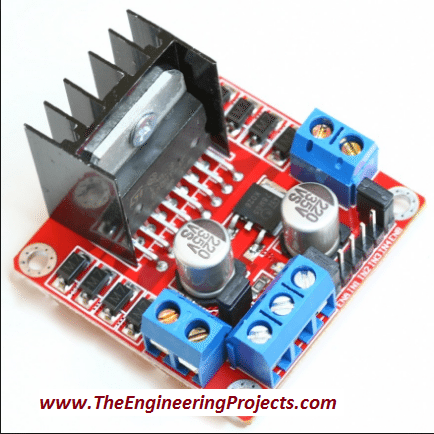
Motor Controller L298
Motor Controller is used to control the direction of DC motor. It consists of an L298 motor driver IC which is capable of rotating the motor in both clockwise and anti clockwise directions by switching its pins from HIGH to LOW and vise versa. Moreover, it needs +12V, GND and +5V in order to power it up. So, we will design a voltage regulator which will step down 12V to 5V. So, let's have a look at this voltage driver in next part:
Voltage Regulator
Voltage regulator is also the part of this design. In our daily life, we need to step up or to step down the voltages according to the requirements. Requirements vary with the different purpose. Small electronics components like micro-controller, LED, LCD etc. So the main purpose of voltage regulator is to step down the voltage from 12V to just 5V in order to fulfill the requirements of the electronic components. Step down transformer can also be used instead of voltage regulator. Due to the huge structure and cost we prefer to use voltage regulator. You should read How to Design a 5V Power Supply in Proteus to get better idea about this voltage regulator. The circuit diagram of the designed voltage regulator is shown in the figure below.
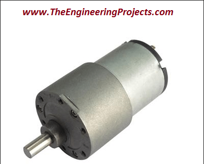
DC Motor
DC motor is the essential part of the different projects and our daily life. for example if we want to automate our house doors i.e if we want to open and close the doors automatically by detecting the person, motor plays a vital role here. Similarly in robotics, vacuum, blowers and air conditioners, DC motor has a wide range of applications.
Jumper Wires
Jumper wires are used to make the connections between all of the components. Use small pieces of the jumper wires in order to give a better look to the designed circuit. If you are using longer wires for the connections, it will create complexity and causes many problems while operating the circuits.
Power Supply
12V power supply is used as the main power supply. As we know, to operate any of the electronic components or electronic appliances we must need the main power supply. Power supply can vary according to the power consumption of the electronic equipment. Here I am using a 12V DC power supply because it is a small and simple project with minimum power requirements.
LCD 20x4
LCD is used to visualize the commands sent to the serial port. It basially display us that which function is being performed at a particular time. A 20×4 LCD is used and is shown in the figure below. If you haven't worked on LCD before, then you should have a look at Circuit Designing of LCD with Arduino in Proteus ISIS.
Assembling of the Components
Here are the few steps followed while designing this DC Motor Direction Control using arduino:- Connect the terminals of the DC motor with the output pins (OUT1 and OUT2) of L298 motor controller.
- Connect L298 motor controller's pin IN1 and IN2 with the Arduino UNO's pin 2 and 5 respectively.
- Now, connect ENA pin of L298 motor controller to the Arduino's pin 9.
- Connect the power supply to turn on the circuit.
- Make sure that you have supplied 12V, 5V and GND properly to the L298 motor controller.
Circuit Diagram

Completely Assembled Diagram
Arduino Code Designing
After making all the connections properly, open your Arduino source code. If you are using Arduino for the first time then you should have a look at Installation of Arduino Driver in Windows.- Attach the Arduino board with your PC and go to Search->Device Manager as shown in the figure below.

- Select the device manger and you can see different options here like Batteries, bluetooth radios, keyboards, monitors, ports etc.
- Open the Ports(COM & LPT) as shown in the figure below.
- See the COM Port supported by Arduino Board which COM5 in this case.

- Now open the Arduino software and go to Tools and select the Arduino board and the COM port properly.
- The description is shown in the figure given below.

- Just copy and paste the source code given below.
#include <LiquidCrystal.h>
//Keyboard Controls:
//
// C - Clockwise
// S - Stop
// A - Anti-clockwise

// Declare L298N Controller pins
// Motor 1
int dir1PinA = 2;
int dir2PinA = 5;
int speedPinA = 7; // PWM control
LiquidCrystal lcd(8, 9, 10, 11, 12, 13);

void setup() {

Serial.begin(9600); // baud rate

lcd.begin(20, 4);
lcd.setCursor(5,0);
lcd.print("DC Motor");
lcd.setCursor(5,1);
lcd.print("Direction");
lcd.setCursor(5,2);
lcd.print("Control");
lcd.setCursor(2,3);
lcd.print("via Arduino UNO");
//Define L298N Dual H-Bridge Motor Controller Pins

pinMode(dir1PinA,OUTPUT);
pinMode(dir2PinA,OUTPUT);
pinMode(speedPinA,OUTPUT);

}

void loop() {

// Initialize the Serial interface:

if (Serial.available() > 0) {
int inByte = Serial.read();
int speed; // Local variable

switch (inByte) {

case 'C': // Clockwise rotation
analogWrite(speedPinA, 255);//Sets speed variable via PWM
digitalWrite(dir1PinA, LOW);
digitalWrite(dir2PinA, HIGH);
Serial.println("Clockwise rotation"); // Prints out “Motor 1 Forward” on the serial monitor
Serial.println("   "); // Creates a blank line printed on the serial monitor
lcd.clear();
lcd.setCursor(0,0);
lcd.print("Clockwise rotation");
break;

case 'S': // No rotation
analogWrite(speedPinA, 0); // 0 PWM (Speed)
digitalWrite(dir1PinA, LOW);
digitalWrite(dir2PinA, LOW);
Serial.println("No rotation");
Serial.println("   ");
//lcd.clear();
lcd.setCursor(5,1);
lcd.print("No rotation");
break;

case 'A': // Anti-clockwise rotation
analogWrite(speedPinA, 255); // Maximum PWM (speed)
digitalWrite(dir1PinA, HIGH);
digitalWrite(dir2PinA, LOW);
Serial.println("Anti-clockwise rotation");
Serial.println("   ");
//lcd.clear();
lcd.setCursor(3,2);
lcd.print("Anti-clockwise");
break;

default:
// Turn off the motor if any other key is being pressed
for (int thisPin = 2; thisPin < 11; thisPin++) {
digitalWrite(thisPin, LOW);
}
Serial.println("Wrong key is pressed");
//lcd.clear();
lcd.setCursor(0,3);
lcd.print("Wrong key is pressed");
  }
    }
      }
- Now, upload the source code onto the Arduino UNO board as shown below.

- In the above figure shows that the source code is uploading to the Arduino board.

- Done uploading shows that the source code has been uploaded successfully to the Arduino borad.
- Now, go to the Serial Monitor on the top right corner of the Arduino software.
- Press C, you can see the DC motor is rotating in the clockwise direction and statement Clockwise rotation will be printed on the Serial Monitor.
- Now, press S, the DC motor will stop and a statement No rotation will be print on the Serial Monitor.
- If you want to rotate DC motor in anti-clockwise direction, press A then, the statement Anti-Clockwise rotation will be printed on the Serial Monitor.
- I have made the logic in such a way that if you press any of the other buttons the DC motor will stop in reaction to that and the statement Wrong key is pressed will be printed on the Serial Monitor.
- All of the above steps are shown in the figure shown below.

Final Testing of DC Motor Direction Control using Arduino
- The screenshot of the actual circuitry for DC Motor Direction Control using Arduino is shown in the below figure:

- You can see in the above figure that we have attached Arduino UNO board with L298 Motor Driver and then we have attached DC Motor with Arduino UNO and LCD is used to show the current movement of Motor.
- Moreover we have also designed a small circuit which I have mentioned above and named as Voltage regulator, and it is used to step down 12V into 5V.


