Hello everyone, I hope you all are doing great. In today's post, I am going to share a Final Year Project in detail, named as Real Time Security Control System using XBee and GSM. I will give you all the details so that you can easily design it on your own. I've given the Proteus Simulation to download below. In that zip file, you will get both the Arduino codes and Proteus Simulations.
I have divided this whole project design into four parts. If you got into any trouble in your project, then ask in comments and I will try my best to resolve them. So, today we are gonna have a look at the basics of this Security project. There are a lot of systems introduced in the market these days that are used to transfer sensor data from one node to another either wirelessly or through some wired connection. The proposed technique also works on this same principle. But a lot of modifications are intended to introduce in order to enhance this technique.
In this project, I have designed a real-time security system, which consists of two wireless nodes named as
Sensor Node
Base Node.
So, first of all, let's have a look at these two nodes one by one. First, I am going to discuss Sensor Node:
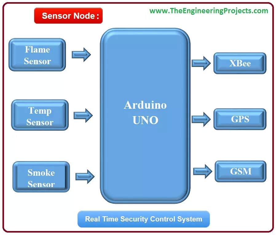
Sensor Node
The sensor node is placed in that building which is needed to be secured. Sensor node consists of three different sensors and two modules used for security purposes named as:
Sensors:
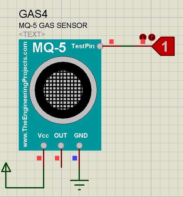
Smoke Sensor: To detect Smoke.
Flame Sensor: Used for Fire Detection.
Temperature Sensor: Measuring Temperature of surroundings.
Modules:
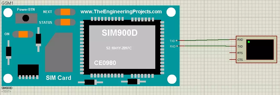
GSM module: is used to deliver the notification message if any fault occurs in the system.
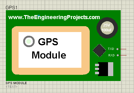
GPS module: is used to locate the exact position of the fault that occurred.
Below two modules are used for controlling purposes:
Modules:
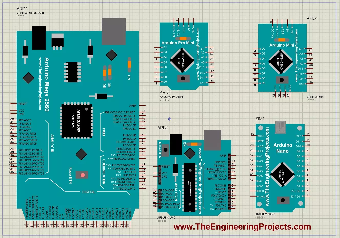
Arduino UNO: All these Sensors and modules are connected to Arduino UNO.
XBee Module: To send sensors' data & GPS Location to Base Node.
Block Diagram for the Sensor Unit of Real Time Security Control System using XBee and GSM is shown in below figure:
Now let's have a look at the Base Unit of Real Time Security Control System using XBee and GSM.
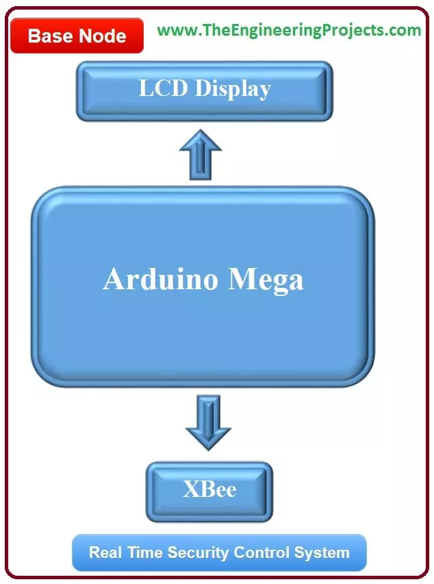
Base Unit:
The base node will be placed in the Control Department. It could be your security guard's room or the nearby police station.
This node will receive the data from the sensor node via XBee module.
So, in total it will have three modules on it which are:
XBee Module: It is used to maintain wireless communication between the sensor node and base node.
LCD 20x4: It is used to display real-time conditions like sensors' values & GPS Location.
Arduino Mega 2560: It is used to control both of these modules.
Here's the block diagram of Base Unit for Real Time Security Control System using XBee and GSM:
Components Selected
In the previous section, we have had a look at the basic Introduction of our Real Time Security Control System using XBee and GSM. This section will elaborate on the selection of the components which is the most important factor before designing any project/product. This is basically a simulation based project so there is no hardware involved in this project. The proposed technique is designed in Proteus ISIS. All of the components are taken from the Proteus library.
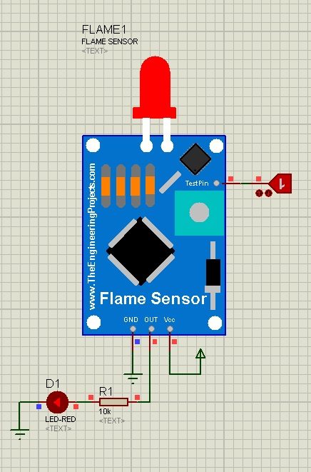
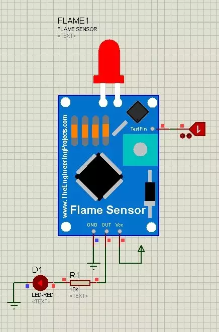
Flame Sensor
The flame sensor is an electronic device usually used for fire detection purposes.
It can be used in homes, industries, offices, schools etc.
A certain threshold is adjusted while designing the algorithm.
When the fire flames cross that particular threshold, the flame sensor will send a signal to Arduino which will send that signal through Xbee to Base Unit immediately.
As soon as the signal will be received on the Base Unit, the alarm will turn ON and hence guards will come to know that this area has become dangerous now.
Immediate precautions must be taken in this case.
Flame Sensor is not available in Proteus so we have designed its library.
The temperature sensor is an electronic sensor used to estimate the temperature in the surroundings.
The temperature range can be adjusted while designing its algorithm.
When the temperature in the surroundings reaches the adjusted threshold, it generates a notification.
Most of the time an alarm is attached to the temperature sensor. The alarm starts to beep when the desired temperature is reached. It can be used in homes, offices and organizations to maintain the temperature of a certain area according to the desired requirements.
But in our project we want to send a signal to the base unit, so that's why this sensor will send a signal to the base unit.
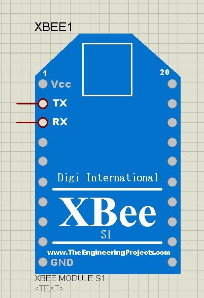
XBee Module
XBee is selected as a wireless module. The proposed technique consists of two XBee modules.
One is attached to the base unit and the other is attached to the sensor unit.
The data is transmitted by the sensor unit via XBee module.
And the XBee module attached to the base unit receives that data from the sensor unit and sends it to the microcontroller to manipulate it.
There are many wireless modules available in the market these days e.g. Radio Frequency (RF) module.
Some of them are not used commonly due to their shorter ranges e.g. Bluetooth module.
XBee module is far better as compared to the Bluetooth module and provides a larger coverage area in comparison to similar wireless modules.
So, XBee is used in this project. XBee module is not available in Proteus so that's why you should download XBee Library for Proteus.
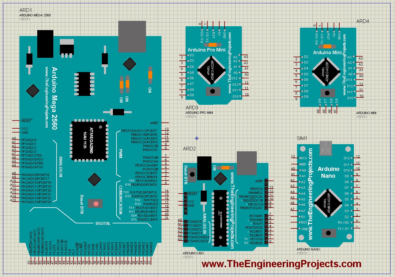
Arduino UNO
The microcontroller plays a vital role in any project and is like a backbone of a particular project.
Arduino UNO and Mega 2560 both are selected as a microcontroller.
Arduino UNO is attached to the sensor unit and Arduino Mega 2560 is attached to the base unit.
Arduino is an open-source device. Students can take online help in almost every task. Online source codes are also available for different tasks.
So, a student can easily perform them with a proper understanding.
So, these are all the components/modules, which I have used in this project. So, in the first part, have seen the basic Introduction of the project and then in the second section, we have had a detailed overview of all the modules used. So, now in the next section which is the third part I am gonna show you How to design these Proteus Simulations.
Proteus Simulation of Security Control System
In this section, we are gonna have a look at how to design these Proteus Simulations for Real Time Security Control System using XBee and GSM. As you know, I have used Arduino so we also need to discuss the code in order to run these simulations. So, first, we will design the proteus simulations and then we will write its code.
Proteus Simulations
I have designed two simulations for this project.
First of all, what you need to do is to download all those above Proteus Libraries and add them properly.
I have given detailed instructions in each post about How to use them.
After adding all these Libraries, now restart your Proteus software and design a circuit for the Sensor Unit.
Proteus Simulation of Sensor Unit is shown in the below figure:
As you can see in the above figure, the Sensor unit consists of three different sensor modules, which are:
Temperature sensor.
Smoke sensor.
Flame sensor.
In this unit, Arduino UNO is used as a microcontroller to get data from all the sensors and this data will be transmitted wirelessly towards the base unit for proper monitoring.
XBee module is used for wireless communication between the sensor unit and the base unit.
GPS module is interfaced in order to locate the exact position of the fault that occurred in the system.
Now we are gonna design our second simulation for the Base Unit.
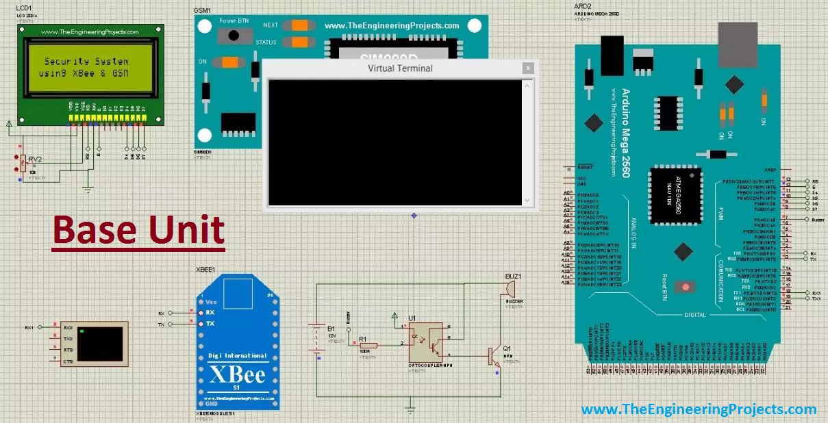
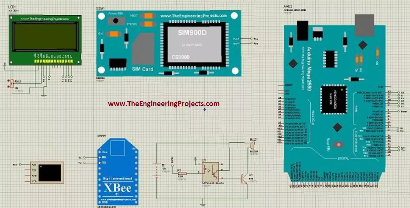
The Proteus Simulation of Base Unit is shown in the below figure:
The base unit is basically a monitoring end of the system.
All the data obtained from the sensors is transmitted by the sensor unit towards the base unit.
The base unit has an Arduino Mega 2560 as a micro-processing unit.
Just like the sensor unit, an XBee module is also attached to the base unit in order to receive the data wirelessly sent by the base unit.
There is an LCD on the base unit. It is used to visualize the obtained results. It displays different messages e.g. fault detection, sensors data etc.
GSM module is used in the base unit to send the notification if a fault occurs in the system or the system is showing some abnormal behavior even for an instance.
This GSM module will also send the location in SMS. You have to enter the number of recipients in the programming code.
Arduino Code of Security Control System
When you download this project, you will get a .rar file and within that file, you will find two folders.
One of them will have the Arduino Codes and the other one will have Proteus Simulations.
I have already added all the hex files so you just need to run these simulations.
If you got into any trouble then use our Contact Form and our team will help you out.
Now coming towards the last section of this project, now I am gonna show you the results of these simulations.
So, I have run both of these Simulations and here's the first look at Base Unit:
The LCD on the base unit is displaying the title of our project.
Virtual Terminal is connected with Arduino so that we could also have a look at incoming or outgoing data.
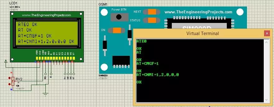
After that first of all, Arduino will communicate with the GSM module and will set its settings, as shown in the below figure:
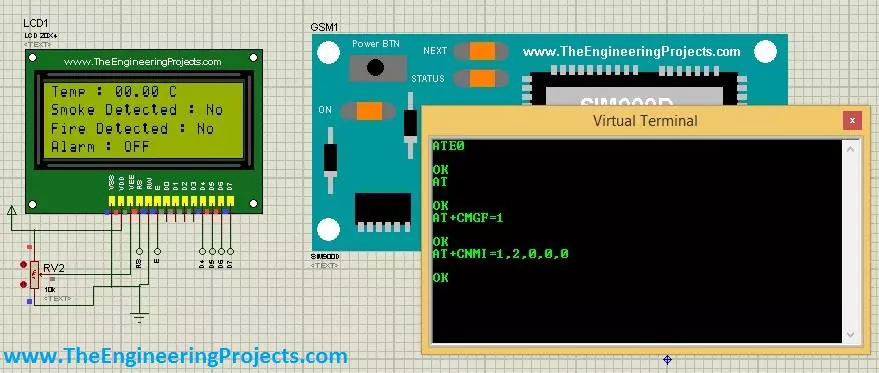
Now our GSM module has configured, so the next screen of the base unit is shown below:
As you can see in the above figure that LCD is displaying the values of all three sensors and because all are normal that's why the Alarm is OFF.
The temp value is 0 because we haven't yet received the data from the sensor unit.
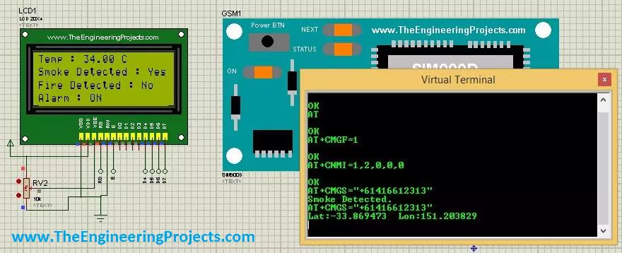
Now let's run our Sensor Unit and make our Fire Sensor HIGH, then you will get results as shown in the below figure:
The alarm is also ON in the above figure and SMS has also been sent which is shown in Virtual Terminal.
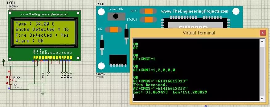
In case, when both fire and smoke are detected, LCD will display smoke as well as fire detection messages.
SMS will also be sent as you can see in the Virtual Terminal. GSM has sent the message indicating Fire Detected and GPS Location.
Base Unit Proteus Simulation is shown in the below figure:
So, whenever you change any of these sensors' values in the Sensor Unit then the respective value will change in the Base Unit.
So, that was all about Real Time Security Control System using XBee and GSM. If you got into any trouble then ask in the comments and I will help you out. Thanks for reading, take care and have fun !!! :)
syedzainnasir
I am Syed Zain Nasir, the founder of The Engineering Projects (TEP). I am a
programmer since 2009 before that I just search things, make small projects and now I am sharing my
knowledge through this platform. I also work as a freelancer and did many projects related to
programming and electrical circuitry. My Google Profile+Follow
Get Connected
Comments on ‘’ Real Time Security Control System using XBee and GSM ‘’ ( 1 )
0
rp
Says:
Thank you for project.But there are some issue , i am doing project on xbee and having some issues.
I tried to download your project but the file is not there at download link. please update that
Reply